CFS8DL5800TSTATSecurity device accessory
Ademco Inc.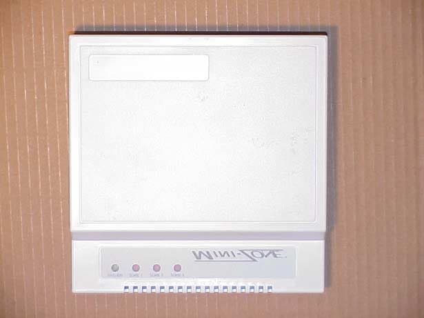
Click to zoom
Application Details
- Equipment Class
- CYY - Communications Receiver used w/Pt 15 Transmitter
- Date of Grant
- Nov 08, 2001
- Application Purpose
- Original Equipment
- Date of Application
- Sep 26, 2001
- Equipment Note
- Security device accessory
- Frequency Range
- 345.00000000 - 345.00000000
- Company
- Ademco Inc.
- Country
- United States
Documents & Files
Document Text
Text extracted from the exhibit documents filed with the FCC. Open a document above to read the original.
Users Manual
® U.S. Registered Trademark Copyright © 2001 Honeywell • •All Rights Reserved INSTALLATION INSTRUCTIONS 69- 1534- 1 W8665A,E RF Receiver Module APPLICATION The W8665A,E RF Receiver Module (RM) provides 24 Vac control of HVAC equipment when used with a T8665A Chronotherm® IV Wireless Programmable Thermostat. The W8665A can be used with 1H/1C single-zone conventional applications. The W8665E can be used with up to three zones when used with a Honeywell EMM-3 Electronic MiniZone© Panel or TZ-3 TotalZone™ Panel. See Table 1. INSTALLATION CAUTION Equipment Damage Hazard. Do not mount W8665 inside HVAC equipment. Mount only on wall. 1. Mount the thermostats in each zone of the living space using the installation instructions provided with each thermostat. 2. Mount the dampers in the ductwork using the installation instructions provided with each damper. 3. Mount the W8665 RF Receiver Module near the HVAC equipment on a wall. See Fig. 1. 4. Level the W8665 for appearance only. Fig. 1. W8665 mounting location. Table 1. W8665 Description. ModelApplicationStagesZonesComments W8665AConventional gas, oil or electric systems. 1H/1COneUse with T8665A Wireless Thermostat. W8665EConventional gas, oil or electric systems. 1H/1CUp to threeUse with T8665A Wireless Thermostats. Use with EMM-3 Electronic MiniZone™ Panel Single or multi-stage conventional or heat pump systems. 1H/1C or up to 3H/2C Use with T8665A Wireless Thermostats. Use with TZ-3 TotalZone™ Zone Control Panel. M20162 WATER HEATER W8665 E L E C T R O N I C A I R C L E A N E R RETURN AIR FURNACE OR BOILER HIGH EFFICIENCY AIR CLEANER W8665A,E RF RECEIVER MODULE 69-1534-12 WIRING All wiring must comply with local electric codes and ordinances. See Fig. 2-4 wiring diagrams for specific applications. Refer to Tables 2 and 3 for terminal designations. CAUTION Voltage Hazard. Can cause electrical shock or equipment damage. Disconnect power before beginning installation. Wiring the W8665A Connect the RF Receiver Module to the equipment loads. See Fig. 2 and Table 2. Wiring the W8665E Connect the RF Receiver Module zones to the appropriate thermostat zone connections on the EMM-3 MiniZone™ Panel or TZ-3 TotalZone ™ Zone Control Panel. See Fig. 3 or 4 and Table 3. Table 2. W8665A Terminal Designations. Te rmina l DesignationFunction R24 Vac transformer hot. Powers RF receiver module. C24 Vac transformer common. Powers RF receiver module. RZ24 Vac system transformer. Not used in single zone applications. YStage 1 cool. WStage 1 heat. GFan. Table 3. W8665E Terminal Designations. Te rmina l DesignationFunction R24 Vac transformer hot. Powers RF receiver module. C24 Vac transformer common. Powers RF receiver module. RZ24 Vac system transformer. Connect to R of Zone1 thermostat on zone panel. RZ24 Vac system transformer. Connect to R of Zone 2 thermostat on zone panel. RZ24 Vac system transformer. Connect to R of Zone 3 thermostat on zone panel. Zone 1 YStage 1 cool. Zone 1 WStage 1 heat. Zone 1 GFan. Zone 2 YStage 1 cool. Zone 2 WStage 1 heat. Zone 2 GFan Zone 3 YStage 1 cool. Zone 3 WStage 1 heat. Zone 3 GFan W8665A,E RF RECEIVER MODULE 369-1534-1 Fig. 2. Connecting the W8665A RF Receiver Module to the equipment. M20163 COMM T8665A THERMOSTAT ZONE 1W8665A LEDLED LED STATES: COMM: RAPIDLY FLASHING GREEN — RECEIVING INFORMATION FROM THERMOSTAT. GREEN OFF — STANDBY, READY TO RECEIVE INFORMATION. ZONE: RED ON — SYSTEM (HEAT, COOL OR FAN) IS ON. RED OFF — SYSTEM (HEAT, COOL OR FAN) IS OFF. FLASHING RED — ERROR. NOT RECEIVING SIGNAL FROM THERMOSTAT. RAPIDLY FLASHING RED — RECEIVER IN SET-UP MODE. DIP SWITCH SETTINGS: OFF: NOT SET-UP TO RECEIVE INFORMATION FROM A THERMOSTAT. ON: READY TO RECEIVE INFORMATION FROM THERMOSTAT AFTER SET-UP IS COMPLETE. SET-UP: MOVE DIP SWITCH TO ON POSITION AND MAKE THERMOSTAT CALL FOR FAN. NOTE: ALL OTHER THERMOSTATS MUST BE OFF (NOT CALLING) DURING SET-UP. ZONE 1 ZONE 2 ZONE 3 ON HEAT RELAY COOL RELAY FAN RELAY L2 L1 (HOT) YWG ZONE 1 RCRZ W8665A,E RF RECEIVER MODULE 69-1534-14 Fig. 3. Connecting the W8665E RF Zone™ Panel to the EMM-3 MiniZone™ Panel to control 1H/1C with up three thermostat zone connections. Fig. 4. Connecting the W8665E RF Zone™ Panel to the TZ-3 TotalZone™Zone Control Panel to operate up to 3H/2C with up to three thermostat zone connections. M20164 R R C C COMM T8665A ZONE 1 THERMOSTAT ZONE 1ZONE 2W8665E LEDLEDLEDLED ZONE 3 YWG M1 M4 M6 C R Y W G ZONE 1 EMM-3 LED STATES: COMM: RAPIDLY FLASHING GREEN — RECEIVING INFORMATION FROM THERMOSTAT. GREEN OFF — STANDBY, READY TO RECEIVE INFORMATION. ZONE: RED ON — SYSTEM (HEAT, COOL OR FAN) IS ON. RED OFF — SYSTEM (HEAT, COOL OR FAN) IS OFF. FLASHING RED — ERROR. NOT RECEIVING SIGNAL FROM THERMOSTAT. RAPIDLY FLASHING RED — RECEIVER IN SET-UP MODE. YWG ZONE 2 YWG ZONE 3 24V, 40 VA TRANSFORMER R C RZ RZ RZ M1 M4 M6 C R Y W GM1 M4 M6 C R Y W G DIP SWITCH SETTINGS: OFF: NOT SET-UP TO RECEIVE INFORMATION FROM A THERMOSTAT. ON: READY TO RECEIVE INFORMATION FROM THERMOSTAT AFTER SET-UP IS COMPLETE. SET-UP: MOVE DIP SWITCH TO ON POSITION AND MAKE THERMOSTAT CALL FOR FAN. NOTE: ALL OTHER THERMOSTATS MUST BE OFF (NOT CALLING) DURING SET-UP. ZONE 1 ZONE 2 ZONE 3 ON T8665A ZONE 2 THERMOSTAT T8665A ZONE 3 THERMOSTAT OC OC TR2 TR1 CR M20165 W8665E YWG W2 L G Y R W M6M4M1 ZONE 1 TZ-3 YWG ZONE 2 YWG ZONE 3 24V, 40 VA TRANSFORMER R C RZ RZ RZ W2 L G Y R W M6M4M1W2 L G Y R W M6M4M1 W8665A,E RF RECEIVER MODULE 569-1534-1 SETUP Setting Up W8665A,E to Receive Signals from the T8665A Thermostat(s) The T8665A Thermostat(s) require(s) setup to send signals to the W8665 Receiver Module to operate: • The W8665A Receiver is used for single-zone applications. • The W8665E RF Zone™ Panel is used for up to three T8665A Thermostats for multi-zone applications. IMPORTANT Be sure the thermostat is at least five feet away from the W8665 during setup. Single Zone Applications (1 W8665A/1 T8665A) 1. Power up the W8665A and install the batteries in the T8665A Thermostat. 2. Place the W8665A Zone 1 DIP switc…
Text truncated - open the document above for the full version.
Cover Letter(s)
Federal Communications Commission ADEMCO Equipment Approval Services 165 Eileen Way PO Box 358315 Syosset, NY 11791 Pittsburgh, PA 15251-5315 09/21/01 SUBJECT: CERTIFICATION OF NEW PRODUCT FCC ID: CFS8DL5800TSTAT Dear Sir, We have e-filed a: 731 form, a 159 form, and the following exhibits: 1-1 a functional description 2-1 a circuit description 2-2 circuit schematics NO 3-1 receiver - no tx timing 4-1 front plastic 4-2 rear plastic 4-3 PCB in plastic 4-4 top of PCB 4-5 bottom of PCB FCC Label location photo FCC Label photo 5-1 how test was run 5-2 picture of test setup 5-3 receiver emissions NO 5-4 receiver - no occupied BW 6-1 test equipment used 7-1 II for 5800TSTAT with FCC STATEMENT The application fee for certification of Ademco's CFS8DL5800TSTAT under FCC Rules and Regulations Part 15, has been sent. If you have any questions or require additional information, please contact the undersigned. Yours Sincerely, Ken Addy Director of Radio Eng.
Operational Description
EXHIBIT 1-1 CFS8DL5800TSTAT FUNCTIONAL DESCRIPTION The 5800TSTAT receiver is part of the wireless thermostat system. The receiver decodes standard messages sent by the CFS8DL5800STAT transmitter.
Operational Description
EXHIBIT 2-1 CFS8DL5800TSTAT CIRCUIT OPERATION The RF signal is fed from switched diversity antennas (ANT1, ANT2) via SW1 to the LNA composed of FL1 and mmic U3 , from there it is fed into a single conversion receiver chip U4. IC U4 contains a rf amp., mixer, phase locked L.O. (locked to Y1), IF amplifiers (fed by FL2) the raw base-band is fed into U1 and U11 for conditioning prior to processing by the microprocessor U5.
Test Report
EXHIBIT 5-1 CFS8DL5800TSTAT Report of Measurements. Measurements were made at Ademco 's Measurement Facility at 160 Eileen Way , Syosset , NY 11791 , FCC Registration number : 90421. Measurements were made in accordance with the procedures and reporting requirements of ANSI C63.4-1992. The Test Set-Up (C63.4 section 10.1.3) is shown in the attached drawing. The sequence of testing (C63.4 section 10.1.7) for radiated emissions is as follows: A preliminary scan was conducted with the receiver antenna close to the EUT in order to identify the emission characteristics of the EUT (C63.4 section 8.3.1.1). The antenna and EUT were then placed at the proper separation with the EUT positioned on a non-conducting turntable. The EUT was rotated on the turntable to maximize the received signal strength, then the receiver antenna height was varied to further maximize the received reading. Thereafter, the device was again rotated to a peak output position and the antenna height was re-adjusted for maximum received signal. This procedure was re-iterated until there was no further increase in signal level. This procedure was performed with the EUT rotating in three orthogonal planes (C63.4 section 13.1.4.1) to generate a final maximum reading which is recorded on the radiated emissions result sheet. Similar measurements were made on the receiver to ensure compliance as an unintentional radiator. See Exhibit 6 for list of test equipment (C63.4 section 10.1.4). Note, Spectrum Analyzer resolution bandwidths set as follows; (Video Bandwidth set greater than RBW) - For occupied bandwidth measurements, RBW = 100kHz, (This is in accordance with the minimum RBW allowed by C63.4, which requires RBW greater than 5% of the FCC required occupied bandwidth spec of 0.25% of center frequency). - For radiated emissions below 1 GHz, the RBW = 100kHz. Detector function set to peak. - For radiated emissions above 1 GHz, the RBW = 1MHz. Detector function set to peak. OCCUPIED BANDWIDTH is shown on attached plot. RADIATED EMISSIONS are recorded on attached sheet.
Test Report
Frequency (MHz) Antenna Polarity ( V-H ) Meter Reading (dB uV) Cable/Amp Factor ( dB ) Antenna Factor (dB/M) Converted Reading ( uV/M ) Duty Cycle ( % ) Corrected Reading ( uV/M ) Limit @ 3 Meter ( uV/M ) 355.7 H 15.0 2.3 15.1 41.69------- 41.69 200 April, 11, 2001 GREG BARBATO KEN ADDY DATE:____________________ TESTED BY:_________________________APPROVED BY:________________________ ADEMCO 5800TSTAT (RECEVER) TEST SAMPLE (model): _______________________________________________________________________________ TEST METHOD: ANSI C63.4-1992 TEST SPECIFICATION: FCC PART 15, SUBPART C. NOTES: 1) DETECTOR = PEAK. 2) FREQUENCY RANGE SCANNED TO 4 GHz. (METER READING +CABLE /AMP FACTOR +ANTENNA FACTOR) 20 3) CONVERTED READING = 10 4) CORRECTED READING = CONVERTED READING X DUTY CYCLE 5) SIX HIGHEST EMISSIONS RECORDED. ALARM DEVICE MANUFACTURING COMPANY 165 EILEEN WAY CFS8DL5800TSTAT SYOSSET, NY 11791 FCC ID#____________________
Test Report
EXHIBIT 6 CFS8DL5800TSTAT Test Equipment list 1. Antenna: RGA-60 S/N: 6127 Cal. on: 10/19/00 Cal. due: 10/19/01 2. Antenna: Log Periodic S/N:365 Cal. on: 07/28/00 Cal. due: 07/28/01 3. Antenna: Roberts dipole S/N:111 Cal. on: 04/25/00 Cal. due 04/25/01 4. Spectrum Analyzer R & S S/N:1065.6000.20 Cal. on: 06/29/00 Cal. due: 06/29/01
Test Report
EXHIBIT 5-1 CFS8DL5800TSTAT Report of Measurements. Measurements were made at Ademco 's Measurement Facility at 160 Eileen Way , Syosset , NY 11791 , FCC Registration number : 90421. Measurements were made in accordance with the procedures and reporting requirements of ANSI C63.4-1992. The Test Set-Up (C63.4 section 10.1.3) is shown in the attached drawing. The sequence of testing (C63.4 section 10.1.7) for radiated emissions is as follows: A preliminary scan was conducted with the receiver antenna close to the EUT in order to identify the emission characteristics of the EUT (C63.4 section 8.3.1.1). The antenna and EUT were then placed at the proper separation with the EUT positioned on a non-conducting turntable. The EUT was rotated on the turntable to maximize the received signal strength, then the receiver antenna height was varied to further maximize the received reading. Thereafter, the device was again rotated to a peak output position and the antenna height was re-adjusted for maximum received signal. This procedure was re-iterated until there was no further increase in signal level. This procedure was performed with the EUT rotating in three orthogonal planes (C63.4 section 13.1.4.1) to generate a final maximum reading which is recorded on the radiated emissions result sheet. Similar measurements were made on the receiver to ensure compliance as an unintentional radiator. See Exhibit 6 for list of test equipment (C63.4 section 10.1.4). Note, Spectrum Analyzer resolution bandwidths set as follows; (Video Bandwidth set greater than RBW) - For occupied bandwidth measurements, RBW = 100kHz, (This is in accordance with the minimum RBW allowed by C63.4, which requires RBW greater than 5% of the FCC required occupied bandwidth spec of 0.25% of center frequency). - For radiated emissions below 1 GHz, the RBW = 100kHz. Detector function set to peak. - For radiated emissions above 1 GHz, the RBW = 1MHz. Detector function set to peak. OCCUPIED BANDWIDTH is shown on attached plot. RADIATED EMISSIONS are recorded on attached sheet.
Contact Information
Applicant
Christian Fouth(Sr. Wireless Certification Engineer)
Technical Contact
Alarm Device Manufacturing CompanyKen L Addy
[email protected]516-921-6704
A Division of Pittway Corporation · Syosset, New York · United States
Non-Technical Contact
Alarm Device Manufacturing CompanyKen L Addy
[email protected]516-921-6704
Test Firm
AdemcoKenneth Addy
Technical Specifications
| # | Rule Parts | Frequency Range | Power Output |
|---|---|---|---|
| 1 | 15B | 345 MHz - 345 MHz | - |
Other Applications from Ademco Inc.

CFS8DL5800MINIV
Jan 28, 2026Wireless Alarm Transmitter
Equipment Class
DXX - Part 15 Low Power Communication Device Transmitter
CFS8DLWTS800
Jan 12, 2026Wireless Alarm Transmitter
Equipment Class
DTS - Digital Transmission SystemCFS8DLCAMWEWI1
Jul 25, 2024VX5 HD Indoor Camera
Equipment Class
DTS - Digital Transmission System
CFS8DLCAMWEWO1
Sep 17, 2023VX3 HD Outdoor Camera
Equipment Class
NII - Unlicensed National Information Infrastructure TX
CFS8DLLMD500A
Jul 20, 2023Wireless door/window contact
Equipment Class
DTS - Digital Transmission System