CFS8DL5804BDMXKey Pad Alarm Accessory
Ademco Inc.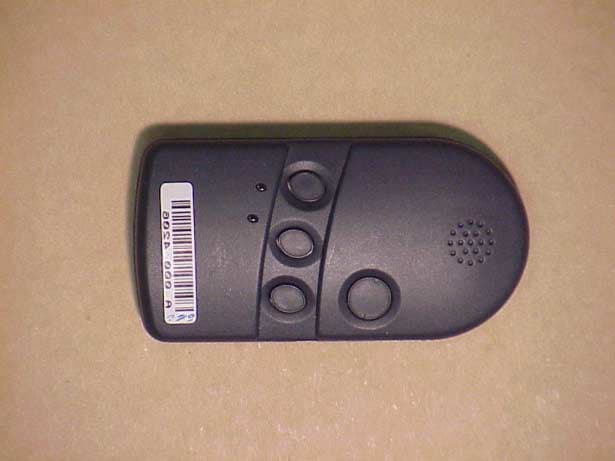
Click to zoom
Application Details
- Equipment Class
- DSR - Part 15 Remote Control/Security Device Transceiver
- Date of Grant
- May 21, 2003
- Application Purpose
- Original Equipment
- Date of Application
- Sep 11, 2002
- Equipment Note
- Key Pad Alarm Accessory
- Frequency Range
- 345.00000000 - 345.00000000
- Company
- Ademco Inc.
- Country
- United States
Documents & Files
Document Text
Text extracted from the exhibit documents filed with the FCC. Open a document above to read the original.
Users Manual
INSTALLATION INSTRUCTIONS GENERAL INFORMATION The 5804BD is a four-button wireless key that permits an alarm system to be controlled remotely. It is a bi- directional device, which means that it can send a command to the control, such as to arm or disarm, and can also receive status back from the control, which is indicated by two bi-color status LEDs and a piezoelectric sounder. Each button can be programmed for any zone response type by using the control’s transmitter “learn” mode. Typical use is for arming, disarming, panic, and output relay operation. The 5804BD must be used in conjunction with a 5800TM (Transmitter Module) and 5881 RF Receiver. The unit is powered by two replaceable Lithium batteries designed to provide up to two years of life (see “To Replace the Battery” for more information). PROGRAMMING THE 5804BD HOUSE ID You need to program a House ID number into the unit before you can to use it to display the system status. The House ID number must be same as the one used in the control panel. The House ID must be in the range of 01 to 31. The default in the 5804BD is 10. To Enter a House ID 1. Enter House ID mode by pressing the “ A ,” “ B ,” and “ C ” buttons at the same time until the Red and Green LEDs alternate flashing. 2. Enter the House ID number by using the “ A ” button to enter the 10’s digit and the “ B ” button to enter the 1’s digit. Note: If the entry is out of range (greater than 31), the unit will generate a long beep and discard the entry. 3. Accept the entry by pressing the “ D ” button. 4. The unit displays the stored number by flashing the left LED for the 10’s digit and flashing the right LED for the 1’s digit (for example, for House ID 21, the left LED will flash twice, the right LED will flash once). 5. The unit will then exit the House ID mode (a beep will be heard). Example: To enter House ID # 17 into the unit: To View the House ID a) Enter House ID mode as described in step 1 (above). b) Depress the “ D ” button to view. c) The unit will display the stored number as described in step 4 (above). d) The unit will then exit House ID mode (a beep will be heard). 5804BD BI-DIRECTIONAL WIRELESS KEY N8209 01/97 Loop Assignments: • Button A =>Loop 3 • Button B =>Loop 2 • Button C =>Loop 4 • Button D =>Loop 1 Note : Place the 5881 receiver and the 5800TM transmitter module in a high, centrally located area for best reception. The 5800TM module must be located between 1 and 2 feet from the receiver. Enter HID mode: Press A + B + C buttons until LEDs flash . Enter HID # 17: Press & release A button once, press & release B button 7 times . To accept entry, press D button . 1 2 3 4 HID will be shown by flashing LEDs. Then exit HID mode. Programming a House ID in the Control Panel • On VISTA 32, 40, 50, 50P, 100, and up, use Device Programming mode to enable the RF receiver and enter the House ID number. • On Via-30, VISTA-20, and below, go to field ✶ 24 and enter the House ID number. PROGRAMMING THE BUTTONS Each 5804BD is assigned a unique serial number during manufacturing. Each button on the unit also has a unique “loop” number that must be programmed into the control panel during installation. Assign each button to an individual zone number and program the Input Type as “BR” --Button Type RF (entry of “ 5 ”) in the control’s Zone Programming mode. Then, input the serial number by one of the following methods: • “Learn” the serial number of the device into the system as described in the control panel’s Installation Instructions. • Enter the serial number manually through the keypad. • Enter the serial number using downloading software. Be sure to include the loop number of each button during programming (see loop assignments on previous page). Button C If you choose not to use the “ C ” button, you must do the following to avoid a “Check” condition when the button is accidentally pressed: 1. Assign this button to a zone (see “Assign a Button to a Zone”). 2. After the serial number has been programmed, re-enter Zone Programming for that zone. 3. At the “Zone Type” prompt, enter 00 and press [ ✶ ]. a) On VISTA-30 controls and below, the system will ask whether you want to permanently delete that zone. Enter 0 (No). This will cause the system to retain the serial number, but render the button inactive. b) On VISTA-40 and above, continue to press [ ✶ ] until you see the “Enter zone No?” prompt again. At this point, Press 00 and [ ✶ ]. Then press ✶ 99 to exit Program mode. Arm/Disarm Button If a button is assigned to a zone type 20 (Arm Stay), 21 (Arm Away), and 22 (Disarm), you must do the following: On Vista 32, 40, 50, 50P, 100, and up You must assign a user to the button in order for it to operate. To assign a user number to the Arm/Disarm button: 1. Enter [4-digit User Code] + 8 + [User No.] + [4-digit new User Code]. 2. Answer Yes or No to the “Open/Close Report ?” question. 3. Answer Yes to the “RF Button ?” question. 4. Enter the zone number assigned to the Arm/Disarm button. 5. Keypad shows the summary of user information on its display. 6. Test Arm/Disarm button to make sure it operates correctly. On Via-30, Vista-20, and below You do not have to assign a user to the button. The panel will report the zone number as the user number to the central station. OPERATING THE BUTTONS To Activate a Button To activate programmed function on a button, press and hold the button down until the yellow LED flashes (2 beeps will be heard), and then release it. To Request System Status Because the 5804BD is a bi-directional device, users can check the system status before arming or disarming their system. To check system status, press and release any button momentarily. The yellow LED will flash after you release the button (1 beep will be heard). After a second or two, the 5804BD will display the system status information using a combination of LED and sounder activity (see the System Status Indications Table, below). If 5804BD does not receive system status informatio…
Text truncated - open the document above for the full version.
Cover Letter(s)
COVER LETTER Oct., 28, 2002 Alarm Device Manufacturing Company TO: Mr. Steve Dayhoff, FCC Application Processing Branch Re: FCC ID CFS8DL5804BDMX Applicant: Alarm Device Manufacturing Company Correspondence Reference Number: 24209 731 Confirmation Number: EA237326 Sir, You wrote: >Please submit the data tables and plots to support the test report description. >It appears the data was omitted from the report. I don't know how that happened, but I'm re-sending it along with this cover letter. Please find EXHIBIT 5-3.PDF, EXHIBIT 5-4.PDF, & EXHIBIT 5-5.PDF uploaded to your site. Best Regards, Greg Barbato for Ken Addy
Cover Letter(s)
Dear Mr. Tannahill, In response to the following letter: >To: Ken Addy, Alarm Device Manufacturing Company >From: George Tannahill >[email protected] >FCC Application Processing Branch >Re: FCC ID CFS8DL5804BDMX >Applicant: Alarm Device Manufacturing Company >Correspondence Reference Number: 25178 >731 Confirmation Number: EA237326 >Per the request pasted below the application has been set aside. >Please make the corrections and the application will be regranted. >>"Sir, >> Apparently, we had a similarly named product (CFS8DL5804BD) that >>was in a adjacent computer folder, and pulled the wrong photos during >>the upload process. The FCC ID is: CFS8DL5804BDMX , the Confirmation >>Number is: EA237326 Please advise us as to how we can rectify this. >>The product was never placed in production. >> Regards, >> Greg Barbato Please note that I am uploading the correct exhibits 4-1 through 4-5. Best Regards, Greg Barbato
Operational Description
EXHIBIT 3-1 CFS8DL5804BDMX 5804BD-MX Duty Cycle Calculation Message protocol, timing and duty cycle calculation: The data output is phase-encoded Manchester that has inherent 50% duty cycle and consists of 64 bits per word sent at a nominal data rate of 3.7 kb/s (3.2kb/s min to 4.2kb/s max). Therefore the duty cycle is calculation is as follows: The word format consists of 64 bits, The duration of each bit is 312.5 uSec max. The duty cycle over a 100 mSec measuring period is calculated as follows: Duty cycle = Actual RF transmission ON time / 100 mSec Actual transmission ON time = 64 bits X 50% X 312.5 uSec = 10 mSec Therefore duty cycle = 10 / 100 mSec = .10 = 10%, and peak to average field strength is 20 db. Total on-air time for a supervision transmission is: 64 X 312.5 uSec + (5 X 150 mSec) = 0.77 seconds The group of six transmissions is repeated twice, with the second group delayed from the first by a max time of 2 seconds. The worst case on-air time is 1.54 + 2 = 3.54 seconds Summary: - Duty cycle = 10% On airtime = 3.54 seconds
Test Report
EXHIBIT 5-1 CFS8DL5804BDMX Report of Measurements. Measurements were made at Ademco 's Measurement Facility at 160 Eileen Way , Syosset , NY 11791 , FCC Registration number : 90421. Measurements were made in accordance with the procedures and reporting requirements of ANSI C63.4-1992. The Test Set-Up (C63.4 section 10.1.3) is shown in the attached drawing. The sequence of testing (C63.4 section 10.1.7) for radiated emissions is as follows: A preliminary scan was conducted with the receiver antenna close to the EUT in order to identify the emission characteristics of the EUT (C63.4 section 8.3.1.1). The antenna and EUT were then placed at the proper separation with the EUT positioned on a non-conducting turntable. The EUT was rotated on the turntable to maximize the received signal strength, then the receiver antenna height was varied to further maximize the received reading. Thereafter, the device was again rotated to a peak output position and the antenna height was re-adjusted for maximum received signal. This procedure was re-iterated until there was no further increase in signal level. This procedure was performed with the EUT rotating in three orthogonal planes (C63.4 section 13.1.4.1) to generate a final maximum reading which is recorded on the radiated emissions result sheet. Similar measurements were made on the receiver to ensure compliance as an unintentional radiator. See Exhibit 6 for list of test equipment (C63.4 section 10.1.4). Note, Spectrum Analyzer resolution bandwidths set as follows; (Video Bandwidth set greater than RBW) - For occupied bandwidth measurements, RBW = 100kHz, (This is in accordance with the minimum RBW allowed by C63.4, which requires RBW greater than 5% of the FCC required occupied bandwidth spec of 0.25% of center frequency). - For radiated emissions below 1 GHz, the RBW = 100kHz. Detector function set to peak. - For radiated emissions above 1 GHz, the RBW = 1MHz. Detector function set to peak. OCCUPIED BANDWIDTH is shown on attached plot. RADIATED EMISSIONS are recorded on attached sheet.
Test Report
EXHIBIT 6 CFS8DL5804BDMX Test Equipment list 1. Antenna: RGA-60 S/N: 3127 Cal. on: 11/01/01 Cal. due: 11/01/02 2. Antenna: Log Periodic S/N:447 Cal. on: 11/01/01 Cal. due: 11/01/02 3. Spectrum Analyzer H. P. 8563E S/N:3246A00232 Cal. on: 03/01/02 Cal. due: 03/01/03
Contact Information
Applicant
Christian Fouth(Sr. Wireless Certification Engineer)
Technical Contact
Alarm Device Manufacturing CompanyKen L Addy
[email protected]516-921-6704
A Division of Pittway Corporation · Syosset, New York · United States
Non-Technical Contact
Alarm Device Manufacturing CompanyKen L Addy
[email protected]516-921-6704
Test Firm
AdemcoKenneth Addy
Technical Specifications
| # | Rule Parts | Frequency Range | Power Output |
|---|---|---|---|
| 1 | 15C | 345 MHz - 345 MHz | - |
Other Applications from Ademco Inc.

CFS8DL5800MINIV
Jan 28, 2026Wireless Alarm Transmitter
Equipment Class
DXX - Part 15 Low Power Communication Device Transmitter
CFS8DLWTS800
Jan 12, 2026Wireless Alarm Transmitter
Equipment Class
DTS - Digital Transmission SystemCFS8DLCAMWEWI1
Jul 25, 2024VX5 HD Indoor Camera
Equipment Class
DTS - Digital Transmission System
CFS8DLCAMWEWO1
Sep 17, 2023VX3 HD Outdoor Camera
Equipment Class
NII - Unlicensed National Information Infrastructure TX
CFS8DLLMD500A
Jul 20, 2023Wireless door/window contact
Equipment Class
DTS - Digital Transmission System