CFS8DL5805Key fob alarm accessory
Ademco Inc.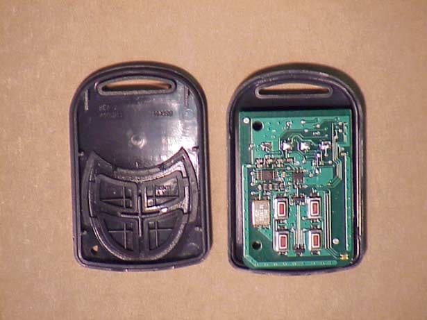
Click to zoom
Application Details
- Equipment Class
- DSC - Part 15 Security/Remote Control Transmitter
- Date of Grant
- Apr 30, 2002
- Application Purpose
- Original Equipment
- Date of Application
- Mar 05, 2002
- Equipment Note
- Key fob alarm accessory
- Frequency Range
- 345.00000000 - 345.00000000
- Company
- Ademco Inc.
- Country
- United States
Documents & Files
Document Text
Text extracted from the exhibit documents filed with the FCC. Open a document above to read the original.
Users Manual
5805-4/6 WIRELESS KEY TRANSMITTER INSTALLATION INSTRUCTIONS GENERAL INFORMATION The 5805-4/6 is a compact, 4-button or 6-button portable wireless transmitter intended for use only with wireless alarm systems that support 5800 Series receivers. Each button on the transmitter may be programmed for any zone response, but is typically used for arming and disarming. This device supports the High-Security mode, which sends rolling-code encrypted messaging to the RF receiver. Important Note: This device must be used with a 5881EN or a 6128RF(UL version) receiver. The 5805-4/6 is powered by one replaceable lithium battery designed to provide up to 4 years of life. For battery installation, see Replacing the Batteries. PROGRAMMING Each 5805-4/6 is assigned a unique serial number during manufacturing. Each button on the unit also has a distinct "loop" number (refer to Figure 1) that you must program into the control panel during installation. Assign each button to an individual zone and designate the Input Type as "BR" (Button Type RF). When you are prompted for the serial number, both press and release twice the button you are programming, or enter it manually through the keypad. For complete details on how to program the 5805-4/6 transmitter's serial number at the control panel, see the control unit's installation instructions. Note: Buttons on this transmitter must be pressed for at least 1/2 second to activate the transmitter. This feature minimizes the possibility of accidental transmissions. ACTIVATING HIGH-SECURITY MODE If Programming 5805-4/6 in the Control 1. Program the button in the control. 2. After programming is complete, exit programming mode and wait 60 seconds. 3. Put the system in Go/No Go mode. 4. To enroll hold Loop1, Loop2, Loop3 and loop 4 down at the same time until the panel beeps. 5. To sync the device in High Security Mode, press any button ONCE, until the panel beeps indicating receipt. 6. For Second serial number Hold Loop1, Loop4 of first Serial # and Loop 2, loop3 of Second serial # at the same time until the panel beeps. NOTE: If no beep is heard, exit Go/No Go mode, and repeat this procedure from Step 3. 7. Exit Go/No Go mode (user code + 1 (OFF)). Figure 1: 5805-6 showing button designations Note 1: To get second serial Loop 1 you need to press and hold Serial # 2 Loop3 and Loop 2,To get Second serial loop 4 you need to hold Serial # 1 Loop 3 and Serial # 2 loop 2 If Programming the 5805-4/6 Locally in the 6128RF Hold Loop 1, Loop 2, Loop 3 and loop 4 Down To enroll the First serial number in the 6128RF. Hold Loop 1, Loop 4 of first Serial # and Loop 2, loop 3 of Second serial # to enroll Second serial number in the 6128RF IF USING TWO RECEIVERS IN HIGH- SECURITY MODE Enroll the 5805-4/6 into the receivers one at a time, by disconnecting Receiver #2, enrolling as described in “Activating High Security Mode” (above). Then, disconnect Receiver #1, reconnect Receiver #2, and repeat the enrollment procedure. This process ensures proper High Security operation with both receivers. 2 REPLACING THE BATTERY 1. Remove case back by using the blade of a small screwdriver to pry it open. 2. Remove old battery 3. Place batter in case back locations (see diagram above). - NEGATIVE END MUST FACE DOWN. 4. To close, snap case front and back together. Important Note: Do not remove Printed Circuit Board. SPECIFICATIONS Unit Dimensions: 55mm x 37mm x 12.7mm Battery: Maxell CR2032, Duracell DL 2032, or Varta CR2032 FOR WARRANTY INFORMATION AND FOR DETAILS REGARDING THE LIMITATIONS OF THE ENTIRE ALARM SYSTEM, REFER TO THE INSTALLATION INSTRUCTIONS FOR THE RECEIVER/CONTROL WITH WHICH THIS DEVICE IS USED. FCC ID: CFS8DL5805 165 Eileen Way, Syosset, New York 11791 Copyright © 1999 PITTWAY CORPORATION THIS DEVICE COMPLIES WITH PART 15 OF FCC RULES. OPERATION IS SUBJECT TO THE FOLLOWING TWO CONDITIONS: (1) THIS DEVICE MAY NOT CAUSE HARMFUL INTERFERENCE, AND (2) THIS DEVICE MUST ACCEPT ANY INTERFERENCE RECEIVED, INCLUDING INTERFERENCE THAT MAY CAUSE UNDESIRED OPERATION.
Cover Letter(s)
To: Andy Leimer [email protected] FCC Application Processing Branch Re: FCC ID CFS8DL5805 Applicant: Alarm Device Manufacturing Company Correspondence Reference Number: 22723 731 Confirmation Number: EA640212 Sir, You wrote: >1) I was unable to understand your calculation. What is Te? Te is the time of one bit cell, each bit requires 3 bit cells. If you look just under the drawing of the message, you will see Te is defined as: 100 uS >Why are you using 66 bits X 3Te? Again, Te is the time of one bit cell, each bit requires 3 bit cells. This is the same encoder chip (HCS 300), and timing calculation used on our already approved 5804E ( FCC ID: CFS8DL5804E ) >Why are you multiplying 27.0 X4 in the final calculation? >Please submit a new exhibit that explains the calculation clearly since one message requires 27 mS, and we send a maximum of 4 messages the total packet time would be: (27 X 4), or 108 mS , during this time, the total time that the transmitter is on is 15.5 mS, thus: 15.5 -------- = 14.3 % 108 . >2) The fundamental data seems low for this device to function properly. >Verify that the data is correct and submit new data as necessary. The fundamental data is correct, and the device does function properly. This transmitter is a 'Key Fob Style' device, designed to be used in close proximity to the system, such as at the front door, or within the house. Since it can arm or disarm the entire system with one keystroke, a large range (such as door or window units, which can be effective to over 1,000 ft) is considered undesirable. Regards, Greg Barbato for: Ken Addy
Operational Description
EXHIBIT 1-1 CFS8DL5805 FUNCTIONAL DESCRIPTION The 5805 is a remote key-fob type transmitter, used to send arm, disarm, and panic messages to Ademco alarm systems. It may also be used to perform auxiliary control of lighting or garage doors, through the system.
Operational Description
EXHIBIT 2-1 CFS8DL5805 CIRCUIT DESCRIPTION The RF transmitter portion of the 5805 key-fob is a single chip (U3) phase locked transmitter, using crystal, Y2 as its FDE. L1 & C6 make up the external tank circuit for the chips internal PA, and L2, C8 provide harmonic suppression, while C9, C10, and C12 match the printed antenna. Microprocessor U1 controls all functions of the key-fob. The 5805 comes in a 4 or 6 button version, but the circuit board is the same for both units, only the number of switches changes.
Operational Description
B
Test Report
EXHIBIT 5-1 CFS8DL5805 Report of Measurements. Measurements were made at Ademco 's Measurement Facility at 160 Eileen Way , Syosset , NY 11791 , FCC Registration number : 90421. Measurements were made in accordance with the procedures and reporting requirements of ANSI C63.4-1992. The Test Set-Up (C63.4 section 10.1.3) is shown in the attached drawing. The sequence of testing (C63.4 section 10.1.7) for radiated emissions is as follows: A preliminary scan was conducted with the receiver antenna close to the EUT in order to identify the emission characteristics of the EUT (C63.4 section 8.3.1.1). The antenna and EUT were then placed at the proper separation with the EUT positioned on a non-conducting turntable. The EUT was rotated on the turntable to maximize the received signal strength, then the receiver antenna height was varied to further maximize the received reading. Thereafter, the device was again rotated to a peak output position and the antenna height was re-adjusted for maximum received signal. This procedure was re-iterated until there was no further increase in signal level. This procedure was performed with the EUT rotating in three orthogonal planes (C63.4 section 13.1.4.1) to generate a final maximum reading which is recorded on the radiated emissions result sheet. Similar measurements were made on the receiver to ensure compliance as an unintentional radiator. See Exhibit 6 for list of test equipment (C63.4 section 10.1.4). Note, Spectrum Analyzer resolution bandwidths set as follows; (Video Bandwidth set greater than RBW) - For occupied bandwidth measurements, RBW = 100kHz, (This is in accordance with the minimum RBW allowed by C63.4, which requires RBW greater than 5% of the FCC required occupied bandwidth spec of 0.25% of center frequency). - For radiated emissions below 1 GHz, the RBW = 100kHz. Detector function set to peak. - For radiated emissions above 1 GHz, the RBW = 1MHz. Detector function set to peak. OCCUPIED BANDWIDTH is shown on attached plot. RADIATED EMISSIONS are recorded on attached sheet.
Test Report
Frequency (MHz) Antenna Polarity ( V-H ) Meter Reading (dB uV) Cable/Amp Factor ( dB ) Antenna Factor (dB/M) Converted Reading ( uV/M ) Duty Cycle ( % ) Corrected Reading ( uV/M ) Limit @ 3 Meter ( uV/M ) 30 H14.3 729 345 V 50.33 2.3 16.662916.014.3 428.6 ----------- 690 V 33.87 3.2 21.56854.714.3125.6 729 1035 H 29.17 3.9 23.83699.014.3102.7 500 1380 H 29.17 4.6 24.91859.514.3126.3 500 1725 V 29.00 5.3 26.671118.114.3164.3 729 2070 H 28.87 6.3 28.471521.914.3223.7 729 2415 H 29.17 6.8 28.961764.214.3259.3 729 2760 H 29.10 7.0 29.751962.414.3228.5 729 3105 H 29.10 7.4 30.002252.614.3331.1 729 3450 H 29.10 12.0 29.954007.214.3589.0 729 4000 H14.3 729 DECEMBER, 14, 2001 GREG BARBATO KEN ADDY DATE:____________________ TESTED BY:_________________________APPROVED BY:________________________ ADEMCO 5805 (TRANSMITTER) TEST SAMPLE (model): _______________________________________________________________________________ TEST METHOD: ANSI C63.4-1992 TEST SPECIFICATION: FCC PART 15, SUBPART C. NOTES: 1) Fo= 345 MHZ 2) DETECTOR = PEAK. 3) FREQUENCY RANGE SCANNED TO 4 GHz. (METER READING +CABLE /AMP FACTOR +ANTENNA FACTOR) 20 4) CONVERTED READING = 10 5) CORRECTED READING = CONVERTED READING X DUTY CYCLE 6) SIX HIGHEST EMISSIONS RECORDED. ALARM DEVICE MANUFACTURING COMPANY 165 EILEEN WAY CFS8DL5805 SYOSSET, NY 11791 FCC ID#____________________
Test Report
EXHIBIT 6 CFS8DL5805 Test Equipment list 1. Antenna: RGA-60 S/N: 3127 Cal. on: 11/01/00 Cal. due: 11/01/02 2. Antenna: Log Periodic S/N:447 Cal. on: 11/01/00 Cal. due: 11/01/02 3. Spectrum Analyzer H. P. 8563E S/N:3246A00232 Cal. on: 03/01/01 Cal. due: 03/01/02
Test Report
EXIBIT 3-1 CFS8DL5805 DUTY CYCLE CALCULATION HCS 300 ENCODER MESSAGE Data T E 3+1+10+11+4 = 29 Calculation is basis of worst case data content in order to maximize duty cycle On-time. Message packet is as follows: 2.3mS preamble 1.0ms header 62 bits at data '0' 4 bits at data '1' 3.9mS guard Total Message packet Time ( (23 + 10 + (66X3) )X 0.1 ) + 3.0 = 23.1 + 3.9 = 27.0 mS Total Message packet On Time (23X.1) + ( (66X2) X 0.1 ) = (155 X 0.1) = 15.5 mS Therefore the duty cycle for the peak to average power conversion is: 15.5 Duty Cycle = = 14.3 % (27.0 X 4)
Contact Information
Applicant
Christian Fouth(Sr. Wireless Certification Engineer)
Technical Contact
Alarm Device Manufacturing CompanyKen L Addy
[email protected]5169216704
A Division of Pittway Corporation · Syosset, New York · United States
Non-Technical Contact
Alarm Device Manufacturing CompanyKen L Addy
[email protected]5169216704
Test Firm
AdemcoKenneth Addy
Technical Specifications
| # | Rule Parts | Frequency Range | Power Output |
|---|---|---|---|
| 1 | 15C | 345 MHz - 345 MHz | - |
Other Applications from Ademco Inc.

CFS8DL5800MINIV
Jan 28, 2026Wireless Alarm Transmitter
Equipment Class
DXX - Part 15 Low Power Communication Device Transmitter
CFS8DLWTS800
Jan 12, 2026Wireless Alarm Transmitter
Equipment Class
DTS - Digital Transmission SystemCFS8DLCAMWEWI1
Jul 25, 2024VX5 HD Indoor Camera
Equipment Class
DTS - Digital Transmission System
CFS8DLCAMWEWO1
Sep 17, 2023VX3 HD Outdoor Camera
Equipment Class
NII - Unlicensed National Information Infrastructure TX
CFS8DLLMD500A
Jul 20, 2023Wireless door/window contact
Equipment Class
DTS - Digital Transmission System