CFS8DL5808APPhotoelectronic Smoke/Heat Detector
Ademco Inc.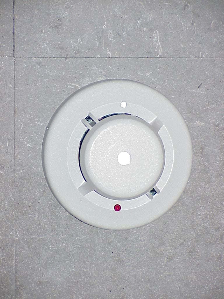
Click to zoom
Application Details
- Equipment Class
- DSC - Part 15 Security/Remote Control Transmitter
- Date of Grant
- Apr 29, 2006
- Application Purpose
- Original Equipment
- Date of Application
- Apr 27, 2006
- Equipment Note
- Photoelectronic Smoke/Heat Detector
- Frequency Range
- 315.00000000 - 315.00000000
- Company
- Ademco Inc.
- Country
- United States
Documents & Files
Document Text
Text extracted from the exhibit documents filed with the FCC. Open a document above to read the original.
Users Manual
Indicator Light Pulsing: Normal/Thermal Alarm Fast Blink: Smoke Alarm None: Call for Service Te st Switch S0162-00 Figure 1. 5808LST Wireless Smoke/Heat Detector PROGRAMMING The smoke detector’s ID must be enrolled in the control panel during installa- tion of the system. The 5808AP must be enrolled on loop 1 as an input “Type 3” (supervised RF). With the control panel in the programming mode, enter the 7 digit serial number that is on the label of the 5808AP. For confirmation, press the test switch to send a transmission to the control panel. See the control unit’s installation instructions for further details. SMOKE DETECTOR LIMITATIONS • Smoke detectors will not sense a fire if the smoke does not reach the sensor or if the air temperature does not reach 135° F. In order for a smoke detector to sense smoke, it must be installed in the immediate vicin- ity of the fire. In addition, smoke from fires in chimneys, in walls, on roofs, in remote parts of the building, or on another level from where the smoke detector is located, may not reach the smoke detector quickly enough for occupants to escape unharmed. For this reason, installer shall install smoke detectors on every level, in every sleeping area, and in every bedroom of the household. • Smoke detectors may not be heard. The alarm horn in this smoke detector meets or exceeds current Underwriter’s Laboratories standards. However, if the smoke detector is not located in the same room as the occupant, or if it is blocked by a closed door or normal noise, the alarm horn may not be heard. In addition, sound sleepers, or persons who are under the influence of drugs or alcohol may not hear the alarm or be able to react to it. Therefore, locate this smoke detector, which has a sounder rated at 85 dB at 10 feet, on every level, in every sleeping area, and in every bedroom of the household. • In general, detectors may not always warn you about fires caused by care- lessness and safety hazards like smoking in bed, violent explosions, escaping gas, improper storage of flammable materials, overloaded electrical circuits, children playing with matches, or arson. • Smoke detectors are not fool-proof. Like all electronic devices, smoke detectors have limitations. No type of smoke detector can sense every kind of fire every time. In addition, smoke from slow, smoldering fires rises slowly and may not reach the smoke detector until actual flame breaks out. This type of smoke may not reach the smoke detector in time for occupants to escape unharmed. • Smoke detectors are not a substitute for life or property insurance. Though smoke detectors have been responsible for saving many lives, they are not warranted or implied to protect lives or property in the event of a fire. Before installing detectors, please thoroughly read these installation instruc- tions and Manual I56-407, Guide for Proper Use of System Smoke Detectors, which provides detailed information on detector spacing, placement, zoning, wiring, and special applications. Copies of this manual are available from ADEMCO. NOTICE: This manual should be left with the owner/user of this equipment. IMPORTANT: This detector must be tested and maintained regularly following NFPA 72 requirements. The detector should be cleaned at least once a year. GENERAL DESCRIPTION The 5808AP photoelectronic smoke/heat detector with built-in wireless trans- mitter is intended for use with wireless alarm systems that support 5800 series devices. Refer to control/communicator installation instructions for compatibil- ity. The 5808AP smoke/heat detector can be used with 5881 series (L, M, H) and 5881EH receivers for residential installations. For commercial installations, the 5881EH receiver should be used. The transmitter can send alarm, tamper, maintenance (when control panels are equipped to process maintenance signals), and battery condition messages to the system’s receiver. The main- tenance signal fully complies with the sensitivity test requirement specified in NFPA 72, 7-2.2. Refer to the wireless system’s instructions for the maximum number of transmitters that can be supported. The 5808AP will sound its built-in temporal horn when smoke activates the detector (also the LED also flashes rapidly), or when the air temperature reaches 135° F (the LED flashes normally, about once every 40 seconds). A message is also sent to the wireless control panel and the smoke detector’s ID number is displayed at the console. The alarm message is transmitted every 4 seconds until the smoke condition has cleared and the detector has reset. After the horn stops, a RESTORE message is transmitted to the control panel and the ID number can be cleared from the panel. During normal and low battery condi - tions, the LED flashes approximately once every 40 seconds. The built-in Drift Compensation algorithm automatically maintains the sensitivity of the detector. Once the detector reaches its limit of compensation, it transmits a maintenance signal to the panel. In maintenance condition, the LED stops flashing. BATTERY INSTALLATION AND REPLACEMENT The 5808AP is powered by two 3-volt CR123A or DL123A Lithium batteries (included). The detector checks for low batteries at least every 60 minutes. If a low battery is detected, the transmitter sends a low battery message to the control panel, which beeps and displays the detector’s ID. This condition will exist for a minimum of seven days, and then the detector’s horn will “chirp” about every 40 seconds. The batteries should be replaced BEFORE the chirps begin. Be sure to replace BOTH batteries with fresh ones. To replace batteries: 1. Remove the detector from its mounting plate by twisting the detector coun - terclockwise. Remove batteries, and dispose properly. 2. Install two new 3-volt CR123A Lithium batteries in the battery compartment. Follow the polarity diagram inside the compartment. 3. Reinstall the smoke detector onto the mounting plate by turning the detec- tor clockwise. 4. Test t…
Text truncated - open the document above for the full version.
Users Manual
CAUTION DO NOT attach the detector to removable ceiling panels. Attach the detector across panel support as shown in Figure 3. TAMPER PROTECTION This detector has a built-in tamper switch that will cause a CHECK signal to be displayed at the console of the detector if it is removed from its installation bracket. The mounting bracket can also be made tamperproof by breaking off the smaller tab at the scribed line (see Figure 2), thus preventing removal of the detector without a tool. To remove the detector, use a small screwdriver to depress the tamperproof tab and turn the detector counterclockwise. TESTING NOTE: Before testing, notify the proper authorities that the smoke detector system is undergoing maintenance and will temporarily be out of ser- vice. Disable the zone or system undergoing maintenance to prevent unwanted alarms. Detectors must be tested after installation and following periodic maintenance. The 5808LST may be tested as follows: A. TEST SWITCH 1. A recessed test switch is located on the detector housing. 2. Push and hold the recessed test switch for a minimum of 5 seconds. Use a small screwdriver or allen key maximum diameter of .18” (The alarm panel will trigger and then the smoke detector will go into alarm. If the tool is removed from the recessed switch the sounder will shut off.) 3. The LED on the detector should blink once per second and the horn should sound within 3 seconds. B. SMOKE ENTRY TEST Hold a smoldering punk stick or cotton wick at the side of the detector and gently blow smoke through the detector until the unit alarms. C. DIRECT HEAT METHOD (Hair dryer of 1000-1500 watts) Direct the heat toward either side thermistor. Be sure to hold the heat source about 12 inches from the detector to avoid damage to the plastic. The detector will reset only after it has time to cool. Smoke detection testing is recommended for verifying system protection capability. A detector that fails to activate with any of these tests should first be cleaned as outlined in this manual’s MAINTENANCE section. If the detector still fails to activate, return for repair. Notify the proper authorities that the system is back on line. TESTING TRANSMITTER SIGNAL NOTE: Remove battery tab before installation. This test should be performed before installation to determine a strong com - munication path with the control panel and after installation is complete. Also, the owner/user should test the unit at least weekly. 1. Activate the wireless system’s TEST mode from the console. 2. Depress and hold the smoke detector’s TEST switch and the detector should immediately transmit an alarm signal to the control panel. The built- in horn will start to sound about 2.5 seconds after depressing the button. 3. The wireless system’s console should emit at least 3 audible sounds when the alarm transmission is received and will display the transmitting detector’s ID number. 4. When the console has received the test signal, release the TEST switch. The horn will immediately stop and a few seconds later the detector’s ID number will clear from the console display. 5. If the console does not respond as noted, check the polarity of the batter - ies and be sure they are fresh. If this is an initial installation, try moving the detector to another location that provides proper reception. Also be sure that the detector’s ID has been “enrolled” by the control panel (see PROGRAMMING). Then, repeat the test. 6. Turn off the system’s TEST mode from the console (security code + OFF). CAUTION Smoke detectors are not to be used with detector guards unless the combina- tion has been evaluated and found suitable for that purpose. WHAT TO DO IN CASE OF FIRE 1. DON’T PANIC — escape may depend on clear thinking. 2. Get out of the house following the planned escape routes, if possible. Do not stop to dress or to collect anything. 3. Open doors carefully only after feeling them to see if they are hot. If a door is hot, do not open it— follow an alternate escape route. 4. Keep close to the floor — smoke and hot gases rise. Breathe through a cloth (wet, if possible) and take short shallow breaths. 5. Keep doors and windows closed unless it is necessary to open them for escape. 6. Meet at your meeting place after leaving your home. 7. Call the local fire department as soon as possible from outside the home. 8. Never re-enter a burning building. For more information about fire safety, contact your local fire department. They can supply more detailed information about making your home as free from fire hazards as possible and about planning for escape in case of fire. MOUNTING First, determine the best location for the smoke detector; a location that pro- vides strong wireless transmission paths and proper smoke detection. A GOOD TRANSMISSION PATH MUST BE ESTABLISHED FROM THE PROPOSED MOUNTING LOCATION BEFORE PERMANENTLY INSTALLING THE DETECTOR. To check, perform the test described in the TESTING TRANSMITTER SIGNAL section of this manual. To mount the detector: 1. Once a suitable location has been determined, install the mounting bracket on the ceiling or on the wall (if local ordinances permit). Use the two screws and anchors provided. 2. Prior to mounting the detector to the mounting bracket, the system must “enroll” the detector’s ID. See the PROGRAMMING section for the steps to follow. 3. Turn the detector in a clockwise direction in the mounting bracket until it clicks into place. 4. Test the detector immediately after completing the installation (as described in the TESTING section of this manual) and refer to the control system’s instructions for additional information concerning the use of wireless smoke detectors. TAMPER SLOT (DEPRESS TAB TO REMOVE DETECTOR) TAMPER RESISTANT TAB (CUT OFF SMALL TAB TO ACTIVATE TAMPER-RESIST FEATURE) ALIGNMENT ARROWS S0158-00 Figure 2. Detector Mounting Bracket S0162-00 Figure 3. Mount Detector Across Ceiling Panel Support AD300-00-00 3 I56-918-14R AD300-00-00 4 I56-918-14R ©2005 Honeywe…
Text truncated - open the document above for the full version.
Block Diagram
EXHIBIT 2-2 BLOCK DIAGRAM CFS8DL5808AP SECTION 2.1033(b) SECTION 2.1033(b) (3) Block Diagram. ENCODER IS: IC3 OCS. IS:Q101 FDE IS: Y1 PA IS:Q102 PA MOD. IS:Q103 &Q104 OCS. SW. IS: Q105
Cover Letter(s)
reply RE: Honeywell International Inc. FCC ID: CFS8DL5808AP Tim, You wrote & I reply: > 1) Operational Description mentions both 315 and 345 MHz. Please review. That was a typo operation is on 315 MHz only. See attached EXHIBIT 1A > 2) Confidentiality has not been requested for items such as schematics, block diagram, operational description. Please clarify if this is requested, and if so, please provide an appropriate cover letter requesting this. Correct as sent no request for confidentiality. > 3) FCC desires actual test photographs and not simply a test diagram or site photographs. Please provide test configuration photographs on the test site if available. Not available, I am writing this into our procedure; you will have them on subsiquent submissions. > 4) Please explain the signaling of the tamper switch. This particular signaling is not life threatening and should meet the FCC 5 second requirement. The ASIC ( Message encoder chip ) takes care of the 5 second requirement. > 5) Please explain the signaling of the test switch. This particular signaling is not life threatening and should meet the FCC 5 second requirement. The ASIC ( Message encoder chip ) takes care of the 5 second requirement. > 6) All measurements appear to be reported for Horizontal polarity only. Were emissions also measured for Vertical polarity? Yes, Vertical polarity was also taken; only highest readings were recorded, they just happen to be all Horizontal this time. > 7) Users manual appears to be missing the information required by 15.21. Please review. Please look at EXHIBIT 7-2 as I had to split the users manual into two parts because of upload size restrictions. > 8) FYI....Reading at 157560 MHz appears to fall in a restricted band and therefore the incorrect limits were applied. However it still meets restricted band limits. Noted & will correct limit notation. Regards, Greg 516-921-6704 Ext 6920 Page 1
ID Label/Location Info
EXHIBIT 8 FCC LABEL CFS8DL5808AP
Operational Description
EXHIBIT 1 FUNCTIONAL DESCRIPTION CFS8DL5808AP SECTION 2.1033(b) SECTION 2.1033(b) (2a). For Part 15 a brief description of the circuit functions of the device. The 5808AP is a battery powered smoke detector & alarm transmitter and is part of a wireless-alarm system. It is used in conjunction with a receiver (5881) to indicate a possible fire event to the alarm system. The 5808AP is identical in construction and operation to the 5808LP-1, except for the operating frequency of 315 MHz. Unlike the 5808LP-1 the 5808AP is only sold in one model (5808AP) that includes both a sounder and thermal detector. The radio circuitry is on the same PCB as the smoke detector. The messages are standard alarm messages transmitted at 315Mhz +/-82Khz using on-off keyed AM modulation. The 5808AP sends a regular supervision or check-in message, no more often than once per hour. As a life/safety device it transmitts for the duration of the alarm. Once the smoke chamber is clear of smoke the alarm ceases, and a single 'restore' message is sent.
Operational Description
EXHIBIT 2-1 CIRCUIT DESCRIPTION CFS8DL5808AP SECTION 2.1033(b) SECTION 2.1033(b) (2a). For Part 15 a statement describing how the device operates. The transmitter is a SAW resonator colpitts oscillator, Q101 etc., that drives a PA Q102 etc., which is on-off keyed (AM) via the modulator Q103 & Q104 etc., The RF energy is coupled out the ANT. via the tuning and coupling of C106 etc., The FDE is the SAW resonator Y1. all control signals (Ocs on / off , Mod. ) come from the micro-controller IC3.
Operational Description
EXHIBIT 3-1 TIMING / DUTY CYCLE CALCULATION CFS8DL5808AP Section 15.255(b) Section 15.255(b), when the radiated emission limits are expressed in terms of the average value of the emission, and pulsed operation is employed, the measurement field strength shall be determined by averaging over one complete pulse train, including blanking intervals, as long as the pulse train does not exceed 0.1 seconds. The exact method of calculating the average field strength shall be submitted with any application for certification. 5808AP Duty Cycle Calculation Message protocol, timing and duty cycle calculation: The data output is phase-encoded Manchester that has inherent 50% duty cycle and consists of 64 bits per word sent at a nominal data rate of 3.7 kb/s (3.2kb/s min to 4.2kb/s max). Therefore the duty cycle is calculation is as follows: The word format consists of 64 bits, The duration of each bit is 312.5 uSec max. The duty cycle over a 100 mSec measuring period is calculated as follows: Duty cycle = Actual RF transmission ON time / 100 mSec Actual transmission ON time = 64 bits X 50% X 312.5 uSec = 10 mSec Therefore duty cycle = 10 / 100 mSec = .10 = 10%, and peak to average field strength is 20 db. Total on-air time for a supervision transmission is: 64 X 312.5 uSec + (5 X 150 mSec) = 0.77 seconds The group of six transmissions is repeated twice, with the second group delayed from the first by a max time of 2 seconds. The worst case on-air time is 1.54 + 2 = 3.54 seconds Summary: - Duty cycle = 10% On airtime = 3.54 seconds
Operational Description
EXHIBIT 3-2 TIMING DIAGRAM CFS8DL5808AP Section 15.255(b) Section 15.255(b), when the radiated emission limits are expressed in terms of the average value of the emission, and pulsed operation is employed, the measurement field strength shall be determined by averaging over one complete pulse train, including blanking intervals, as long as the pulse train does not exceed 0.1 seconds. The exact method of calculating the average field strength shall be submitted with any application for certification. SEE THE NEXT PAGE
Test Report
EXHIBIT 5-1 CFS8DL5808AP Report of Measurements. Measurements were made at Honeywells Measurement Facility at 165 Eileen Way , Syosset , NY 11791 , FCC Registration number : 90421. Measurements were made in accordance with the procedures and reporting requirements of ANSI C63.4-2003. The Test Set-Up (C63.4 section 10.1.3) is shown in the attached drawing. The sequence of testing (C63.4 section 10.1.7) for radiated emissions is as follows: A preliminary scan was conducted with the receiver antenna close to the EUT in order to identify the emission characteristics of the EUT (C63.4 section 8.3.1.1). The antenna and EUT were then placed at the proper separation with the EUT positioned on a non-conducting turntable. The EUT was rotated on the turntable to maximize the received signal strength, then the receiver antenna height was varied to further maximize the received reading. Thereafter, the device was again rotated to a peak output position and the antenna height was re-adjusted for maximum received signal. This procedure was re-iterated until there was no further increase in signal level. This procedure was performed with the EUT rotating in three orthogonal planes (C63.4 section 13.1.4.1) to generate a final maximum reading which is recorded on the radiated emissions result sheet. Similar measurements were made on the receiver to ensure compliance as an unintentional radiator. See Exhibit 6 for list of test equipment (C63.4 section 10.1.4). Note, Spectrum Analyzer resolution bandwidths set as follows; (Video Bandwidth set greater than 3 X RBW) - For occupied bandwidth measurements, RBW = 100kHz, (This is in accordance with the minimum RBW allowed by C63.4, which requires RBW greater than 5% of the FCC required occupied bandwidth spec of 0.25% of center frequency). - For radiated emissions below 1 GHz, the RBW = 100kHz. Detector function set to peak. - For radiated emissions above 1 GHz, the RBW = 1MHz. Detector function set to peak. OCCUPIED BANDWIDTH is shown on attached plot. RADIATED EMISSIONS are recorded on attached sheet.
Test Report
HONEYWELL SECURITY & CUSTOM ELECTRONICS 165 EILEEN WA Y SYOSSET, NY 11791EXHIBIT 5-3 FCC ID # CFS8DL5808AP Date : 3/22/2006 Tested by :Y. Mohammed Approved by :K.Addy Test Sample (model) : 5808AP Transistor - N10-55GN Test method: ANSI C63.4 - 2003 Test specification: FCC Part 15, Sub-part C Notes: (1) Fo = 315MHz. (2) Detector = Peak (3) Frequency range scanned to 4 GHz. Emissions not reported were more than 20dB below the specified unit. [(Meter reading + Cable/Amp factor + Antenna factor) / 20 )] (4) Conv. Reading = 10 (5) Corr. Reading = Conv. Reading X Duty Cycle (6) Six Highest Emissions Recorded Freq. (MHz) Antenna Polarity (V/H) Meter Reading (dB uV) Cable/Amp Factor (dB) Antenna Factor (dB/m) Conv. Reading (uV/M) Duty Cycle (%) Corr. Reading (uV/M) Limit @ 3M (uV/M) 30 CABLE "A"BICONILOG604.0 315H77.001.113.6238547.810.0%3854.86042.0 630H48.001.618.362500.310.0%250.0604.2 945H43.001.821.622094.110.0%209.4604.2 1260H41.002.324.422432.210.0%243.2500.0 1575H34.002.726.401428.910.0%142.9604.2 1890H41.002.928.464149.510.0%415.0604.2 2205H40.003.130.334693.510.0%469.4500.0 2520 H 40.003.3 31.405432.510.0%543.3604.2 2835H37.003.631.604073.810.0%407.4500.0 3150H37.004.131.784405.510.0%440.6604.2 4000 CABLE "A"BICONILOG
Test Report
5808AP OCCUPIED BANDWIDTH (455 KHz)
Test Report
EXHIBIT 6 TEST EQUIPMENT USED CFS8DL5808AP Section 15.231 and ANSI C63.4 Section 15.231, per C63.4. This is a list of all test equipment used. Test Equipment list 1. Antenna: BICONOLOG S/N: 00029290 Cal. on: 09/12/05 Cal. due: 09/12/06 2. Spectrum Analyzer H. P. 8563E S/N:3246A00232 Cal. on: 08/20/05 Cal. due: 08/20/06
Contact Information
Applicant
Christian Fouth(Sr. Wireless Certification Engineer)
Technical Contact
Honeywell International Inc.Ken Addy
[email protected]516-921-6704
165 Eileen Way · Syosset, New York · United States
Test Firm
Honeywell International Inc.Kenneth Addy
Technical Specifications
| # | Rule Parts | Frequency Range | Power Output |
|---|---|---|---|
| 1 | 15.231 | 315 MHz - 315 MHz | - |
Other Applications from Ademco Inc.

CFS8DL5800MINIV
Jan 28, 2026Wireless Alarm Transmitter
Equipment Class
DXX - Part 15 Low Power Communication Device Transmitter
CFS8DLWTS800
Jan 12, 2026Wireless Alarm Transmitter
Equipment Class
DTS - Digital Transmission SystemCFS8DLCAMWEWI1
Jul 25, 2024VX5 HD Indoor Camera
Equipment Class
DTS - Digital Transmission System
CFS8DLCAMWEWO1
Sep 17, 2023VX3 HD Outdoor Camera
Equipment Class
NII - Unlicensed National Information Infrastructure TX
CFS8DLLMD500A
Jul 20, 2023Wireless door/window contact
Equipment Class
DTS - Digital Transmission System