CFS8DL5808W3APPhotoelectric Smoke/Heat Detector
Ademco Inc.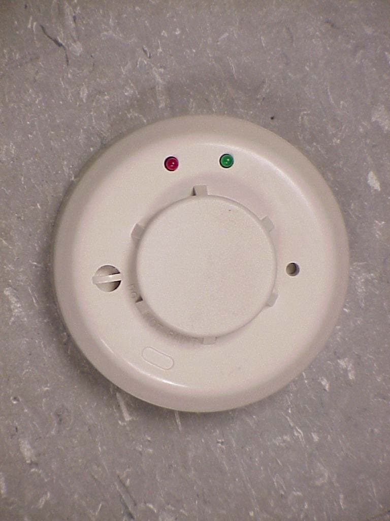
Click to zoom
Application Details
- Equipment Class
- DSC - Part 15 Security/Remote Control Transmitter
- Date of Grant
- Jun 07, 2007
- Application Purpose
- Original Equipment
- Date of Application
- Jun 06, 2007
- Equipment Note
- Photoelectric Smoke/Heat Detector
- Frequency Range
- 315.00000000 - 315.00000000
- Company
- Ademco Inc.
- Country
- United States
Documents & Files
Document Text
Text extracted from the exhibit documents filed with the FCC. Open a document above to read the original.
Users Manual
INSTALLATION AND MAINTENANCE INSTRUCTIONS 5808W3AP Photoelectronic Smoke/Heat Detector with Built-in Wireless Transmitter D100-100-00 1 I56-2768-000 Before installing detectors, please thoroughly read these installation instructions and Manual I56-407, Guide for Proper Use of System Smoke Detectors, which provides detailed information on detector spacing, placement, zon- ing, wiring, and special applications. Copies of this manual are available from Honeywell. NOTICE: This manual should be left with the owner/user of this equipment. IMPORTANT: This detector must be tested and maintained regularly following NFPA 72 requirements. The detector should be cleaned at least once a year. General Description The5808W3APphotoelectronic smoke/heat detector with built-in wireless transmitter is intended for use with wireless alarm systems that support 5800 series devices. Refer to control/communicator installation instructions for compatibility. The5808W3AP smoke/heat detector can be used with 5881 series (L, M, H) and 5881EH receivers for residential installations. For commercial installations, the 5881EH receiver should be used. The transmitter can send alarm, tamper, maintenance (when control panels are equipped to process maintenance signals), and battery con - dition messages to the system’s receiver. The maintenance signal fully complies with the sensitivity test requirement specified in NFPA 72, 7-2.2. Refer to the wireless system’s instructions for the maximum number of transmitters that can be supported. The 5808W3AP incorporates a state-of-the-art optical sensing chamber and an advanced microprocessor. The micropro - cessor allows the detector to automatically adjust its sen- sitivity back to the factory setting when it becomes more sensitive due to contaminants settling in its chamber. In order for this feature to work properly, the chamber must never be opened while power is applied to the smoke detector. This includes cleaning, maintenance or screen replacement. All models also feature a restorable, built- in, fixed temperature (135°F) thermal detector and is also capable of sensing a freeze condition if the temperature is below 41°F. The 5808W3 contains a piezoelectric horn which generates the ANSI S3.41 temporal pattern in an alarm condition. In alarm, a message is also sent to the wireless control panel and the smoke detector’s ID number is displayed at the console. The alarm message is transmitted every 4 seconds until the smoke or heat condition has cleared and the detector has reset. During an alarm condition, pressing the detectors test switch will silence the piezoelectric horn for 5 minutes. Once the detector has reset, a RESTORE message is transmitted to the control panel and the ID number can be cleared from the panel. The built-in Drift Compensation algorithm automatically maintains the sensitivity of the detector. Once the detector reaches its limit of compensa - tion, it transmits a maintenance signal to the panel. The mounting base installation is simplified by the incorpora - tion of features compatible with drywall fasteners. Two LEDs on the detector provide a local visual indication of the detector’s status: Table 1: Detector LED Modes Green LEDRed LEDPiezoelectric Horn Power-upBlink 5 secBlink 5 secOff Normal (standby)Blink 10 sec —Off Out of sensitivity —Blink 5 secOff Freeze Trouble —Blink 10 secOff Smoke Alarm —Blink 1 secTemporal Pattern Thermal Alarm ---Blink 4 secTemporal Pattern Low Battery ---Blink 45 secChirp 45 sec During an initial power-up delay, the red and green LEDs will blink synchronously once every five seconds. It will take approximately 20 seconds for the detector to finish the power-up cycle (see Table 2). After power-up has completed and the detector is function - ing normally within its listed sensitivity range, the green LED blinks once every ten seconds. If the detector is in need of maintenance because its sensitivity has shifted outside the listed limits, the red LED blinks once every five seconds. When alarm has been activated by smoke, the red LED blinks every 1 second. During a thermal alarm condi- tion (>135°F) the red LED blinks once every 4 seconds. The LED indication must not be used in lieu of the tests specified under Testing. In a freeze trouble condition, the red LED will blink once every 10 seconds (refer to Table 1). February 22, 2005 3825 Ohio Avenue, St. Charles, Illinois 60174 800/736-7672, FAX: 630/377-6495 www.systemsensor.com D100-100-00 7 I56-2768-000 ©2005 ADEMCO Please refer to insert for the Limitations of Fire Alarm Systems Smoke detectors shall be replaced after being in service for 10 years. However, any smoke detector, fire alarm equipment, or any component of that system which fails prior to that shall be repaired or replaced as soon as possible. Batteries shall be replaced upon indication of a pre-low battery condition. HONEYWELL One-Year Limited Warranty Honeywell International Inc. (“Seller”), 165 Eileen Way, Syosset, NY 11791, warrants its security equipment (the “product”) to be free from defects in materials and workmanship for one year from date of original purchase, under normal use and service. Seller’s obligation is limited to repairing or replacing, at its option, free of charge for parts, labor, or transportation, any part proven to be defective in materials or workmanship under normal use and service. Seller shall have no obligation under this warranty otherwise if the product is altered or improperly repaired or serviced by anyone other than the seller. In case of defect, contact the security professional who installed and maintains your security system or the Seller for product repair . This one year Limited Warranty is in lieu of all other express warranties, obligations, or liabilities. THERE ARE NO EXPRESS WARRANTIES WHICH EXTEND BEYOND THE FACE HEREOF. ALL IMPLIED WARRANTIES, OBLIGATIONS, OR LIABILITIES MADE BY SELLER IN CONNECTION WITH THIS PRODUCT, INCLUDING ANY IMPLIED WARRANTY OF MERCHANTABI…
Text truncated - open the document above for the full version.
Block Diagram
EXHIBIT 2-2 BLOCK DIAGRAM CFS8DL5808W3AP SECTION 2.1033(b) SECTION 2.1033(b) (3) Block Diagram. ENCODER IS: IC1 OCS. IS:Q102 FDE IS: XL1 PA IS:Q103 PA MOD. IS:Q104 &Q105 OCS. SW. IS: Q101
Cover Letter(s)
Untitled RE: 5808W3AP Tim, You wrote, I reply: Regards Greg 1) Users Manual missing 15.21 information. Please update. Please see the new uploaded exhibit: EXHIBIT 7A 2) Please explain how tamper and maintenance signals meet the 5 second requirement as well. The supervision signal ("maintenance signal") is generated by the RF Control micro: IC3 (see block diagram or schematic) If a tamper event occurs it is also processed by the micro. The micro will not allow violation of the 5 second rule by the supervision signal or the tamper. 3) Some data sheets mention the incorrect year of C63.4. Please correct. Please see the new uploaded exhibit: 5808W3AP EXHIBIT 5-3A 4) 1575 MHz appears to fall in a restricted band and therefore the incorrect limit is applied. Please correct. Please see the new uploaded exhibit: 5808W3AP EXHIBIT 5-3A Page 1
ID Label/Location Info
EXHIBIT 8 THE FCC LABEL FOR THE 5808W3AP CFS8DL5808W3AP SECTION 2.1033 (c) and Part 15.21 SECTION 2.1033 (c) Label and label location - A photo showing the identification label clearly (you must be able to see the name and FCC ID number), and the location on the device. In lieu of a photo for this, you may submit a engineer’s drawing. Part 15.21 Statement - for all intentional and unintentional radiators is also printed on the label. All devices shall bear the following statement in a conspicuous location on the device: “ This device complies with Part 15 of the FCC Rules Operation is subject to the following two conditions: (1) this device may not cause harmful interference, and (2) this device must accept any interference received, including interference that may cause undesired operation. “ ENGINEERS DRAWING / LABEL ART: EXACT PHYSICAL LOCATION ON UNIT:
Operational Description
5808W3AP Cover Letter CFS8DL5808W3AP To Whom It May Concern: The 5808W3AP is functionally identical to our previously certified 5808W3 ( FCC ID: CFS8DL5808W3 ). Electronically is also almost identical with the exception of the operating frequency which is 315 MHz.
Operational Description
EXHIBIT 1 FUNCTIONAL DESCRIPTION CFS8DL5808W3AP SECTION 2.1033(b) SECTION 2.1033(b) (2a). For Part 15 a brief description of the circuit functions of the device. The 5808W3AP is a battery powered smoke detector & alarm transmitter and is part of a wireless-alarm system. It is functionally identical to our previously certified 5808W3 ( FCC ID: CFS8DL5808W3 ). The 5808W3AP is also electronically almost identical with the exception of the operating frequency which is 315 MHz.It is used in conjunction with a receiver (5882AP) to indicate a possible fire event to the alarm system. All circuitry is on the same PCB. The messages are standard alarm messages transmitted at 315Mhz +/-82Khz using on-off keyed AM modulation. The 5808W3AP sends a regular supervision or check-in message, no more often than once per hour.
Operational Description
EXHIBIT 2-1 CIRCUIT DESCRIPTION CFS8DL5808W3AP SECTION 2.1033(b) SECTION 2.1033(b) (2a). For Part 15 a statement describing how the device operates. The transmitters oscillator is turned on by switch Q101. Thea SAW resonator colpitts oscillator, Q102 etc.,drives a PA Q103 etc., which is on-off keyed (AM) via the modulator Q104 & Q105 etc., The RF energy is coupled out the ANT. via the tuning and coupling of C117 etc., The FDE is the SAW resonator XL101. all control signals (Ocs on/off , Mod. ) come from the micro-controller IC3.
Operational Description
EXHIBIT 3-1 TIMING / DUTY CYCLE CALCULATION CFS8DL5808W3AP Section 15.255(b) Section 15.255(b), when the radiated emission limits are expressed in terms of the average value of the emission, and pulsed operation is employed, the measurement field strength shall be determined by averaging over one complete pulse train, including blanking intervals, as long as the pulse train does not exceed 0.1 seconds. The exact method of calculating the average field strength shall be submitted with any application for certification. 5808W3AP Duty Cycle Calculation Message protocol, timing and duty cycle calculation: The data output is phase-encoded Manchester that has inherent 50% duty cycle and consists of 64 bits per word sent at a nominal data rate of 3.7 kb/s (3.2kb/s min to 4.2kb/s max). Therefore the duty cycle is calculation is as follows: The word format consists of 64 bits, The duration of each bit is 312.5 uSec max. The duty cycle over a 100 mSec measuring period is calculated as follows: Duty cycle = Actual RF transmission ON time / 100 mSec Actual transmission ON time = 64 bits X 50% X 312.5 uSec = 10 mSec Therefore duty cycle = 10 / 100 mSec = .10 = 10%, and peak to average field strength is 20 db. Total on-air time for a supervision transmission is: 64 X 312.5 uSec + (5 X 150 mSec) = 0.77 seconds The group of six transmissions is repeated twice, with the second group delayed from the first by a max time of 2 seconds. The worst case on-air time is 1.54 + 2 = 3.54 seconds Summary: - Duty cycle = 10% On airtime = 3.54 seconds
Operational Description
EXHIBIT 3-2 TIMING DIAGRAM CFS8DL5808W3AP Section 15.255(b) Section 15.255(b), when the radiated emission limits are expressed in terms of the average value of the emission, and pulsed operation is employed, the measurement field strength shall be determined by averaging over one complete pulse train, including blanking intervals, as long as the pulse train does not exceed 0.1 seconds. The exact method of calculating the average field strength shall be submitted with any application for certification. SEE THE NEXT PAGE
Test Report
HONEYWELL SECURITY & CUSTOM ELECTRONICS 165 EILEEN WA Y SYOSSET, NY 11791EXHIBIT 5-3 FCC ID # CFS8DL5808W3AP Date : 12/01/2006 Tested by :Y. Mohammed Approved by :K.Addy Test Sample (model) : 5808W3AP Smoke Detector Test method: ANSI C63.4 - 2003 Test specification: FCC Part 15, Sub-part C Notes: (1) Fo = 315MHz. (2) Detector = Peak (3) Frequency range scanned to 4 GHz. Emissions not reported were more than 20dB below the specified unit. [(Meter reading + Cable/Amp factor + Antenna factor) / 20 )] (4) Conv. Reading = 10 (5) Corr. Reading = Conv. Reading X Duty Cycle (6) Six Highest Emissions Recorded Freq. (MHz) Antenna Polarity (V/H) Meter Reading (dB uV) Cable/Amp Factor (dB) Antenna Factor (dB/m) Conv. Reading (uV/M) Duty Cycle (%) Corr. Reading (uV/M) Limit @ 3M (uV/M) 30 CABLE "A"BICONILOG604.0 315H77.601.113.6241304.810.0%4130.56042.0 630H48.001.618.362500.310.0%250.0604.2 945H39.001.821.621321.310.0%132.1604.2 1260H40.002.324.422167.710.0%216.8500.0 1575H38.002.726.402264.610.0%226.5 500.0 1890H31.002.928.461312.210.0%131.2604.2 2205H37.003.130.333322.810.0%332.3500.0 2520 H 39.003.3 31.404841.710.0%484.2604.2 2835H36.003.631.603630.810.0%363.1500.0 3150H30.004.131.781967.910.0%196.8604.2 4000 CABLE "A"BICONILOG
Test Report
EXHIBIT 5-1 CFS8DL5808W3AP Report of Measurements. Measurements were made at Honeywells Measurement Facility at 160 Eileen Way , Syosset , NY 11791 , FCC Registration number : 90421. Measurements were made in accordance with the procedures and reporting requirements of ANSI C63.4-2003. The Test Set-Up (C63.4 section 10.1.3) is shown in the attached drawing. The sequence of testing (C63.4 section 10.1.7) for radiated emissions is as follows: A preliminary scan was conducted with the receiver antenna close to the EUT in order to identify the emission characteristics of the EUT (C63.4 section 8.3.1.1). The antenna and EUT were then placed at the proper separation with the EUT positioned on a non-conducting turntable. The EUT was rotated on the turntable to maximize the received signal strength, then the receiver antenna height was varied to further maximize the received reading. Thereafter, the device was again rotated to a peak output position and the antenna height was re-adjusted for maximum received signal. This procedure was re-iterated until there was no further increase in signal level. This procedure was performed with the EUT rotating in three orthogonal planes (C63.4 section 13.1.4.1) to generate a final maximum reading which is recorded on the radiated emissions result sheet. Similar measurements were made on the receiver to ensure compliance as an unintentional radiator. See Exhibit 6 for list of test equipment (C63.4 section 10.1.4). Note, Spectrum Analyzer resolution bandwidths set as follows; (Video Bandwidth set greater than RBW) - For occupied bandwidth measurements, RBW = 100kHz, (This is in accordance with the minimum RBW allowed by C63.4, which requires RBW greater than 5% of the FCC required occupied bandwidth spec of 0.25% of center frequency). - For radiated emissions below 1 GHz, the RBW = 100kHz. Detector function set to peak. - For radiated emissions above 1 GHz, the RBW = 1MHz. Detector function set to peak. OCCUPIED BANDWIDTH is shown on attached plot. RADIATED EMISSIONS are recorded on attached sheet.
Test Report
EXHIBIT 5-4 OCCUPIED BANDWIDTH CFS8DL5808W3AP
Test Report
EXHIBIT 6 TEST EQUIPMENT USED CFS8DL5808W3AP Section 15.231 and ANSI C63.4 Section 15.231, per C63.4. This is a list of all test equipment used. Test Equipment list 1. Antenna: BICONOLOG S/N: 00045682 Cal. on: 04/24/06 Cal. due: 04/23/07 2. Spectrum Analyzer TEK 2784 S/N: B010165 Cal. on: 10/16/06 Cal. due: 10/15/07
Contact Information
Applicant
Christian Fouth(Sr. Wireless Certification Engineer)
Technical Contact
Honeywell International Inc.Ken Addy
[email protected]516 921 6704
165 Eileen Way · Syosset, New York · United States
Test Firm
Honeywell International Inc.Kenneth Addy
Technical Specifications
| # | Rule Parts | Frequency Range | Power Output |
|---|---|---|---|
| 1 | 15.231 | 315 MHz - 315 MHz | - |
Other Applications from Ademco Inc.

CFS8DL5800MINIV
Jan 28, 2026Wireless Alarm Transmitter
Equipment Class
DXX - Part 15 Low Power Communication Device Transmitter
CFS8DLWTS800
Jan 12, 2026Wireless Alarm Transmitter
Equipment Class
DTS - Digital Transmission SystemCFS8DLCAMWEWI1
Jul 25, 2024VX5 HD Indoor Camera
Equipment Class
DTS - Digital Transmission System
CFS8DLCAMWEWO1
Sep 17, 2023VX3 HD Outdoor Camera
Equipment Class
NII - Unlicensed National Information Infrastructure TX
CFS8DLLMD500A
Jul 20, 2023Wireless door/window contact
Equipment Class
DTS - Digital Transmission System