CFS8DL5809XTWireless Rate-of-Rise Heat Detector
Ademco Inc.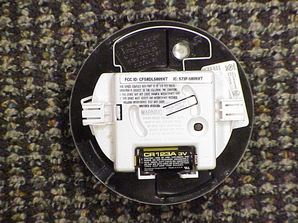
Click to zoom
Application Details
- Equipment Class
- DSC - Part 15 Security/Remote Control Transmitter
- Date of Grant
- Nov 20, 2011
- Application Purpose
- Original Equipment
- Date of Application
- Nov 20, 2011
- Equipment Note
- Wireless Rate-of-Rise Heat Detector
- Frequency Range
- 344.94000000 - 344.94000000
- Company
- Ademco Inc.
- Country
- United States
Documents & Files
Document Text
Text extracted from the exhibit documents filed with the FCC. Open a document above to read the original.
Users Manual
5809 Wireless Rate-of-Rise Heat Detector – Installation Instructions General Information The Honeywell 5809 Rate-of-Rise Heat Detector is a wireless device used with alarm systems that support Honeywell’s 5800 series devices. The 5809 combines a rate-of-rise sensor and a fixed temperature sensor in one device. The rate-of-rise sensor detects a rapid rise in temperature and signals an alarm if the rise is 15 F (8 C) or more per minute. Fires typically cause a rapid rise in temperature in the surrounding area. The fixed temperature sensor will signal an alarm when the ambient temperature rises above 135 F (57 C). IMPORTANT: The 5809 will be permanently damaged if stored, shipped, or installed in environments where the temperature exceeds 120 F (48 C). If the metal disc is detached, the detector has exceeded 135 F (57 C) and must be replaced. Heat detectors should be used for property protection. Reliance should not be placed solely on heat detectors for life safety. When life safety is involved, smoke detectors MUST also be used. Detectors MUST NOT be painted. Notes: It is not recommended to install at a site where the ambient temperature exceeds 100 F. UL: Unit is for dry, indoor use only. If the fixed temperature sensor activates, the detector must be replaced. When the battery voltage drops below a threshold, a low battery signal is sent to the control panel. The 5809 includes a tamper switch. If removed from its mounting base, a trouble signal is sent to the control panel. Detectors should never be relocated without the advice or assistance of the alarm service company. Replace the battery when the system reports a low battery condition. SPECIFICATIONS Battery 3-volt lithium; Duracell DL123, DL123A, or Panasonic CR123A. Operating Temp. 40 F to 140 F (6 C to 60 C) Rate of Rise Temp. 15 F (8 C) increase per minute. Note: The rate-of-rise sensor does not operate above 100 F (38 C). Fixed Temp. 135 F (57 C) Maximum Spacing 50ft x 50ft UL: 30ft x 30ft Refer to NFPA 72 for application requirements. Dimensions 4.9” diameter, 2.7” deep zzz 1 Install the Battery 1. If the 5809 is already mounted, remove the detector assembly by twisting counter-clockwise and withdraw it from the mounting base. DO NOT touch the metal disc. 2. Remove the old battery and wait 30 seconds. 3. Install or replace battery with a Duracell DL123, DL123A, or Panasonic CR123A. Observe polarity! BATTERY 5809EN-003-V0 2 Program the Detector NOTE: The detector’s serial number is located on the product carton, and inside the detector. This number must be enrolled in the control panel. Refer to the control panel’s installation guide for details. 1. Remove the detector assembly by twisting counter-clockwise and withdraw it from the mounting base. DO NOT touch the metal disc. 2. Install the battery (if not already installed). Observe polarity! 3. Enter the control panel’s programming mode. When programming this device, program the following: Input Type = 3 (Supervised RF) Loop number = 1 4. To enable the control panel to capture the detector’s serial number, when prompted force the detector to transmit by momentarily depressing the Activation Button. Alternately, you can manually enter the detector’s serial number. 5. Test the detector after enrolling into the system. Refer to the Testing the Detector topic. 5809EN-001-V0 ACTIVATION BUTTON DETECTOR ASSEMBLY INDEX TA B TAMPER SWITCH 3 Select a Location and Mount the Detector SELECT A LOCATION Refer to the “Specifications” topic for maximum spacing requirements. Avoid mounting the detector near heat generating devices (e.g., ovens, heat vents, furnaces, boilers). Wall Mounting – Mount the detector 4” to 6” from the ceiling. Ceiling Mounting – Mount the detector at least 4” from any wall. Ensure the ceiling temperature will not exceed 100 F. Verify a good RF transmission path from the selected mounting location before mounting. Test the detector first before mounting. Testing The Detector : This test should be performed to verify a good RF transmission path before mounting the detector at the intended location, and again after the installation is complete. CAUTION: The rate-of-rise heat sensor is intended for a one time use. Prolonged heat during testing can damage the detector. If used carefully, following the instructions below, the heat from a portable hair dryer can be used to test the detector. If the metal disc on the detector detaches, the detector must be replaced. 1. Activate the control panel’s test mode. 2. Use either method below to activate the detector: Press and release the activation button on the sensor’s PC board. Holding a portable hair dryer about 12 to 18 inches away from the detector, air the warm air at the side of the detector. 3. Verify the system’s keypads beep and the detector’s serial number is displayed. 4. Exit the control panel’s test mode. MOUNT THE DETECTOR The detector’s mounting base has a variety of holes to accommodate securing it to; a wall, ceiling, 4” junction box, or a 3–1/4” octagon box. 1. Use at least two mounting holes. 2. When securing to wallboard, in addition to the mounting holes, ensure to also use a screw in the Anti-Twist mounting hole. This will prevent the base plate from coming loose when untwisting the sensor. 5809EN-002-V0 INDEX TAB RECESS INDEX TAB RECESS ANTI-TWIST MOUNTING HOLE MOUNTING HOLES 3. Secure the sensor to the mounting base by aligning the sensor’s index tabs to the index tab recesses on the mounting base. While pushing in, turn the sensor clockwise until it locks. DO NOT touch the metal disc. TO THE INSTALLER The rate-of-rise sensor may be subject to reduced sensitivity over time. Annual testing of the rate-of-rise operation is recommended. Regular maintenance and inspection (at least annually) by the installer and frequent testing by the user are vital to continuous satisfactory operation of any alarm system. The installer should assume the resp…
Text truncated - open the document above for the full version.
Users Manual
Détecteur de température thermovélocimétrique 5809 – Guide d’installation Information générale Le détecteur de chaleur thermovélocimétrique 5809 de Honeywell est un dispositif sans fil utilisé avec les systèmes qui supportent des dispositifs de la série 5800. Le 5809 associe un capteur thermovélocimétrique et un capteur thermostatique dans la même unité. Le capteur thermovélocimétrique détecte une élévation rapide de la température et signale une alarme si l’élévation est de 8 C (15 F) ou plus par minute. Les feux causent habituellement une élévation rapide de la température autour d’eux. Le capteur thermostatique signale une alarme quand la température ambiante s’élève au-dessus de 57 C (135 F). IMPORTANT : Le 5809 sera endommagé de façon permanente s’il est entreposé, expédié ou installé à des endroits où la température est supérieure à 48 C (120 F). Si le disque de métal est détaché, le détecteur a dépassé 57 C (135 F) et doit être remplacé. Des détecteurs de chaleur devraient être utilisés pour la protection des biens. Pour la protection de la vie, la confiance ne devrait pas reposer uniquement sur les détecteurs de chaleur. Quand la protection de la vie est en cause, des détecteurs de fumée DOIVENT aussi être utilisés. Les détecteurs NE DOIVENT PAS être peints. Notes : Il n’est pas recommandé d’installer un détecteur de chaleur à un endroit où la température ambiante excède 38 C (100 F). UL : L’unité doit être utilisée seulement à l’intérieur au sec. Si le capteur thermostatique s’active, le détecteur doit être remplacé. Lorsque la tension de la pile baisse sous un seuil, un signal de pile faible est transmis au panneau de commande. Le 5809 est doté d’un interrupteur antisabotage. Si le détecteur est séparé de sa plaque de montage, un signal de défectuosité est transmis au panneau de commande. Les détecteurs ne devraient jamais être changés d’emplacement sans avoir préalablement obtenu l’avis ou l’assistance d’un représentant d’une entreprise de sécurité. Quand le système signale une condition de pile faible, remplacez la pile. SPÉCIFICATIONS Pile 3 volts au lithium; Duracell DL123, DL123A, ou Panasonic CR123A. Température de fonctionnement 6 C à 60 C (40 F à 140 F) Vitesse d’élévation de la température Élévation de 8 C (15 F) par minute. Note : Le capteur thermovélocimétrique ne fonctionne pas à une température supérieure à 38 C (100 F). Température fixe 57 C (135 F) Surface maximale 50 pi x 50 pi UL : 30 pi x 30 pi Pour les exigences d’application, reportez-vous à NFPA 72. Dimensions Diamètre de 4,9 po, épaisseur de 2,7 po zzz 1 Mise en place de la pile 1. Si le 5809 est déjà installé, enlevez le corps du détecteur en le faisant pivoter dans le sens contraire des aiguilles d’une montre et retirez-le de la plaque de montage. NE TOUCHEZ PAS au disque de métal. 2. Enlevez l’ancienne pile et attendez 30 secondes. 3. Installez ou remplacez la pile en utilisant une pile de rechange Duracell DL123, DL123A ou Panasonic CR123A. Vérifiez la polarité! Pile 5809FR-003-V0 2 Programmation du détecteur NOTE : Le numéro de série du détecteur est indiqué sur la boîte du produit et à l’intérieur du détecteur. Ce numéro doit être enrôlé dans le panneau de commande. Pour des détails, consultez le guide d’installation du panneau. 1. Enlevez le corps du détecteur en le faisant pivoter dans le sens contraire des aiguilles d’une montre et retirez-le de la plaque de montage. NE TOUCHEZ PAS au disque de métal. 2. Installez la pile (si ce n’est pas déjà fait). Vérifiez la polarité! 3. Entrez dans le mode de programmation du panneau de commande. Pour programmer ce dispositif, entrez ce qui suit: Type d’entrée = 3 (RF supervisé) Numéro de boucle = 1 4. Pour activer la saisie du numéro de série du détecteur par le panneau de commande, à l’invite, forcez le détecteur à transmettre en appuyant momentanément sur le bouton Activation. Vous pouvez aussi entrer manuellement le numéro de série du détecteur. 5. Après l’avoir enrôlé dans le système, testez le détecteur. Reportez- vous à la rubrique Test du détecteur . 5809FR-001-V0 Bouton d’activation Languette Interrupteur antisabotage 3 Choix d’un emplacement et installation du détecteur CHOISISSEZ UN EMPLACEMENT Reportez-vous à la rubrique « Spécifications » pour les exigences d’espace maximal. Évitez d’installer le détecteur près d’appareils générant de la chaleur (p. ex., des fours, des évents de chaleur, des fournaises, des chaudières). Installation au mur – Installez le détecteur à une distance de 4 à 6 po du plafond. Installation au plafond – Installez le détecteur à au moins 4 po de tout mur. Assurez-vous que la température du plafond n’excédera pas 38 C (100 F). Assurez-vous d’une bonne voie de transmission à partir de l’emplacement choisi avant de faire l’installation. Vérifiez d’abord le détecteur avant de l’installer. Test du détecteur : Ce test devrait être exécuté pour s’assurer d’une bonne voie de transmission avant d’installer le détecteur à l’endroit choisi, et une autre fois après avoir terminé l’installation. MISE EN GARDE: Le capteur thermovélocimétrique est conçu pour être utilisé une seule fois. Le soumettre à de la chaleur durant une longue période durant le test peut l’endommager. S’il cela est fait soigneusement, en suivant les instructions ci-dessous, la chaleur d’un séchoir à cheveux portatif peut être utilisée pour tester le détecteur. Si le disque de métal sur le détecteur se détache, le détecteur doit être remplacé. 1. Activez le mode de test du panneau de commande. 2. Utilisez l’une des méthodes qui suivent pour activer le détecteur : Appuyez momentanément sur le bouton Activation sur le circuit imprimé du capteur. En tenant un séchoir à cheveux portatif à environ 12 à 18 po du détecteur, envoyez de l’air chaud sur le côté du détecteur. 3. Vérifiez que les claviers du système émettent des bips et que le numéro de série est affiché. 4. Quittez le mode de test du panne…
Text truncated - open the document above for the full version.
External Photos
EXHIBIT 4-1 CFS8DL5809XT / 573F-5809XT EXTERNAL PHOTOS: THIS IS THE TOP VIEW: THIS IS THE BACK ( "BOTTOM" ) VIEW:
ID Label/Location Info
EXHIBIT 8 CFS8DL5809XT / 573F-5809XT LABEL INFORMATION: TWO VIEWS OF THE LABEL ON THE REAR PLASTIC COVER :
Internal Photos
EXHIBIT 4-2 CFS8DL5809XT / 573F-5809XT INTERNAL PHOTOS: THIS IS THE PCB IN PLASTIC: THIS IS THE PCB TOP VIEW: THIS IS THE PCB BOTTOM VIEW:
Test Report
EXHIBIT 5-1 CFS8DL5809XT / 573F-5809XT Report of Measurements Measurements for the Intentional Radiator,and OBW were made in accordance with the procedures and reporting requirements at: Honeywell's OATS ( FCC No: 152762 & IC No:573F-1 ) which is located at: 2 Corporate Center Drive, Melville, NY 11747. Measurements were m ade in accordance with the procedure and reporting requirements of ANSI C63.4-2003. The Test Set-Up (C63.4 section 10.1.3) is shown in EXHIBIT 5-2; "Test Setup Photos". The sequence of testing (C63.4 section 10.1.7) for radiated emissions is as follows: A preliminary scan was conducted with the receiver antenna close to the EUT in order to identify the emission characteristics of the EUT (C63.4 section 8.3.1.1). The antenna and EUT were then placed at the proper separation ( 3 Meters) with the EUT positioned at a height of 80 cm on a non-conducting turntable. The EUT was rotated on the turntable to maximize the received signal strength, then the receiver antenna height was varied between one (1) and four (4) Meters to further maximize the received reading. Thereafter, the device was again rotated to a peak output position and the antenna height wa s re-adjusted for maximum received signal. This procedure was re-iterated until there was no further increase in signal level. This procedure was performed with the EUT rotating in three orthogonal planes (C63.4 section 13.1.4.1) to generate a final maximum reading which is recorded on the radiated emissions result sheet. Similar measurements were made on the receiver to ensure compliance as an unintentional radiator. Note, The Spectrum Analyzer resolution bandwidths set as follows; (Video Bandwidth is always set 3X greater than RBW) For occupied bandwidth measurements, RBW = 30KHz and VBW = 100KHz. For radiated emissions below 1 GHz, the RBW = 100kHz. Detector function set to peak. For radiated emissions above 1 GHz, the RBW = 1MHz. Detector function set to peak. TRANSMITTER RADIATED EMISSIONS are recorded in "EXHIBIT 5-3". OCCUPIED BANDWIDTH is recorded in "EXHIBIT 5-4". IF REQUIRED RECEIVER RADIATED EMISSIONS are recorded in "EXHIBIT 5-5". IF REQUIRED LINE CONDUCTED EMISSIONS are recorded in "EXHIBIT 5-6". TEST EQUIPMENT ( per C63.4 section 10.1.4) is recorded in "EXHIBIT 6".
Test Report
HONEYWELL SECURITY & CUSTOM ELECTRONICSREV 10-17-2011-G 2 Corporate Center Drive Melville, NY 11747 EXHIBIT 5-3FCC ID: CFS8DL 5809XT Date :3-Oct 2011Tested by: 5809XT PRESCAN: Notes: (1) Fo:344.94 (2) Detector = Peak (3) Frequency range scanned to 4 GHz. V/V 78.92Emissions not reported were more than 20dB below the specified unit. H/V 71.46 [(Meter reading + Cable/Amp factor + Antenna factor) / 20 )] V/H 76.57 (4) Conv. Reading = 10 H/H 79.20 (5) Corr. Reading = Conv. Reading X Duty Cycle V/O 60.77 (6) Six Highest Emissions Recorded H/O 70.35 Freq. (MHz): Sense Antenna Polarity (V/H): THE ORENTATION OF THE UUT Meter Reading (dB uV): Cable/Amp Factor (dB): Antenna Factor (dB/m): Conv. Reading (uV/M): Duty Cycle (%): Corr. Reading (uV/M): Limit @ 3M (uV/M): HV 344.94HH79.22.515.47 72,193.8 10.0% 7219.47288 689.88HH46.83.719.363,118.9 10.0%311.9729 1034.82HH44.34.722.723,854.8 10.0%385.5500 1379.76HV30.15.625.471,145.5 10.0%114.6500 1724.70HO27.46.327.641,161.4 10.0%116.1729 2069.64HH23.67.329.851,083.9 10.0%108.4729 2414.58HH20.28.131.891,017.4 10.0%101.7729 2759.52 HH 20.7 8.6 32.831,279.4 10.0%127.9500 3104.46HH199.132.631,088.9 10.0%108.9729 3449.40HH1910.033.141,275.0 10.0%127.5729 4000 LAST CAL 17 OCT 11 CABLE D LAST CAL 21-AUG-11 BICONILOG S/N:00045682 Approved by: K. EskildsenY. MOHAMMED Test Sample (model): Test specification: FCC Part 15, Sub-part C and RSS 210 , Issue 8 Test method: ANSI C63.4 - 2004
Test Report
EXHIBIT 6 TEST EQUIPMENT USED CFS8DL5809XT / 573F-5809XT Part 15.231, ANSI C63.4 , RSS 210 This is a list of all test equipment used. Test Equipment list for Honeywell OAT S & Conducted Line: Equipment Mfg Model Cal Date Cal Due Spectrum Analyzer Rohde & Schwarz FSEA20 10/19/10 10/19/11 Antenna (‘Biconilog’) ETS (EMCO)Lindgren 3149 08/22/11 08/22/12 PLEASE SEE PAGE 2-3 FOR TEST EQUIPMENT TRACEABILITY If you need any additional information from Honeywell please contact: Greg Barbato RF Engineer (Acting for Ken Eskildsen) Phone (Direct): (516) 577-5863 Email: [email protected] Cert l.D.: 86798 An ESCO Technologies Company 1301 Arrow Point Drive Cedar Park, Texas 78613 (512) 531-6498 Operating Range: 80 MHz - 6 GHz Instrument Type: Biconilog (Type 5) Date Code: Afternate lD: 11242 Customer: HONEYWELL (NY) 26 - 1000 MHz, +/-0.9 dB; 1000 - 2000 MHz, +L0.8 dB; 2000 - 6000 MHz, +l-1 .2 dB 26 - 1000 MHz, +/-0.9 dB; 1000 - 2000 MHz, +10.8 dB; 2000 - 6000 MHz, +f l .3 dB 26 - 1000 MHz, +/-'1 .0 dB; 1000 - 2000 MHz, +l-1 .4 dgi 2000 - 6000 MHz, +12.3 dB Manufacturer: Model Number: ETS-Lindgren 31 49. s 000023192 22-Aug-11 3 meter, Horizontal and Vertical N'Jl,,r. K S\ETS.LINDGREIU- ;.:::;lii,-:,..,; *ffil"+ IACCREDITEDI Calibr.tlon taboreio.y Codltlc.to 1207,01 Certificate of Cal i bration Conformance Page I of 5 The instrument identifed below has been individually calibrated in compliance with the following standard(s): SAE, ARP-958 - 2003, Electromagnetic lnterference Measurement Antennas; Standard Calibration Method, Society of Automotive Engineers, Aerospace Recommended Practice. Fixed height, three antenna rotation, 1 meter separation. 3 meter separation performed per Annex C. Vertical calibration performed per above listed methodology. Environment: Laboratory MTE is maintained in a temperature controlled environment with ambient conditions from 18 to 28 C, relative humidity less than 90%. The instrument under test has been calibrated on an open air test site (OATS) with environment temperature conditions ranging from 0 to 40 C which has no known influences on measurement quality. Serial Number/ lD: 00045682 Tracking Number: Date Completed: Test Type: CalibrationUncertainty: 01m k=2, (95ok Confidence Level) 03m Test Remarks: Calibrated down to 26 MHz per customer request. Calibration Traceability: All Measuring and Test Equipment (MffE) identified below are traceable to the Sl units through the National lnstitute for Standards and Technology (NIST). Calibraiion Laboratory and Quality System controls are compliant with ISO/lEC 17025-2005 and ANSI/NCSL 2540-1 -1994. Standards and Equipment Used: Make / Model / Name / S/N / Recall Date Condition of Instrument Upon Receipt: In Tolerance to Internal Qualitv Standards On Release: In Tolerance to Internal Qualitv Standards Anritsu MS4623A Network Analyzer 99220119-Mar-12 This document provides traceability of measurements to recognized national standards using contrblled processes at the ETS-L|ndgren Calibration Laboratory. UncertaintieslistedarederivedfromthemethodsdescribedbyNlSTTechNotel29T. Thiscertificateandreportmaynotbereproduced,exceptinfull,withoutthe written approval of ETS-Lindgren Calibration Laboratory in accordance with ISO/IEC 1 7025-2005 and ANSI/NCSL 2540-1 -1994. QAF 1 1 27 (03/1 1 ) Calibration and fssued on 22-Aug-1
Test Setup Photos
EXHIBIT 5-2 CFS8DL5809XT / 573F-5809XT TEST SETUP PHOTOS: SENSE: HORZ UUT: HORZ SENSE: HORZ UUT: VERT SENSE: HORZ UUT: OBLQ SENSE: VERT UUT: HORZ SENSE: VERT UUT: VERT SENSE: VERT UUT: OBLQ
Contact Information
Applicant
Christian Fouth(Sr. Wireless Certification Engineer)
Technical Contact
Honeywell International Inc.Kenneth Eskildsen
[email protected]516 577 5878
2 Corporate Center Drive · Melville, New York · United States
Test Firm
Honeywell International Inc.Mark Schmidt
Technical Specifications
| # | Rule Parts | Frequency Range | Power Output |
|---|---|---|---|
| 1 | 15.231 | 344.94 MHz - 344.94 MHz | - |
Other Applications from Ademco Inc.

CFS8DL5800MINIV
Jan 28, 2026Wireless Alarm Transmitter
Equipment Class
DXX - Part 15 Low Power Communication Device Transmitter
CFS8DLWTS800
Jan 12, 2026Wireless Alarm Transmitter
Equipment Class
DTS - Digital Transmission SystemCFS8DLCAMWEWI1
Jul 25, 2024VX5 HD Indoor Camera
Equipment Class
DTS - Digital Transmission System
CFS8DLCAMWEWO1
Sep 17, 2023VX3 HD Outdoor Camera
Equipment Class
NII - Unlicensed National Information Infrastructure TX
CFS8DLLMD500A
Jul 20, 2023Wireless door/window contact
Equipment Class
DTS - Digital Transmission System