CFS8DL5815-1Door/Window Security Transmitter
Ademco Inc.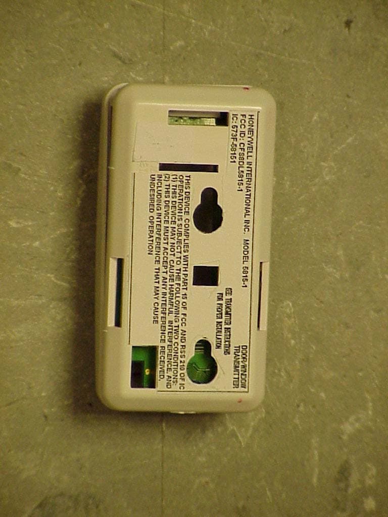
Click to zoom
Application Details
- Equipment Class
- DSC - Part 15 Security/Remote Control Transmitter
- Date of Grant
- Nov 13, 2006
- Application Purpose
- Original Equipment
- Date of Application
- Nov 12, 2006
- Equipment Note
- Door/Window Security Transmitter
- Frequency Range
- 345.00000000 - 345.00000000
- Company
- Ademco Inc.
- Country
- United States
Documents & Files
Document Text
Text extracted from the exhibit documents filed with the FCC. Open a document above to read the original.
Users Manual
5815-1 INSTALLATION INSTRUCTIONS WIRE ENTRY Figure 1. Mounting Plate and Case GENERAL INFORMATION The 5815 is a two-zone Door/Window Transmitter that has its own unique serial number. The control unit is required to "enroll" the serial number prior to its usage in the alarm system. Refer to the control unit's installation instructions for further details. Note: During programming of the control unit, 5815 transmitters should be treated as "RF" (i.e., supervised RF) Type (mandatory for UL installations). The 5815 provides two input loops (zones): the firstfor a wired closed-circuit contact loop, and the second for its built-in reed switch (used in conjunction with a magnet, as described below). One or both inputs may be used. For UL installations, a contact may not be more than 3 feet from the transmitter. The 5815 includes a built-in cover tamper, which is activated when the cover is removed. MOUNTING For proper orientation of the unit in relation to the mounting plate, loop wiring, and/or magnet, read all of this section before installing the unit. The description that follows assumes that the unit will be mounted as shown in the diagrams, with the magnet (if used) located in one of the positions shown in Figure 2. The unit may, however, be installed in any direction, as long as the relationship of the unit to its mounting plate and (if used) magnet is maintained. Although the unit can be mounted directly to a surface, we recommend that the mounting plate be used, for ease in removing the unit for servicing should it become necessary. Before mounting the transmitter permanently, conduct Go/No Go tests (see control's instructions) to verify adequate signal strength and reorient or relocate the transmitter if necessary. 1. Remove the transmitter's top cover by inserting the flat blade of a small screwdriver into the pry-off slot at one end of the unit (see Fig. 1 for location), and slightly twisting the blade until the cover disengages. Figure 2. 5815 (shown without cover) 1. 2. Disengage the attached mounting plate from the case by inserting the blade of a small screwdriver into the locking tab release window (see Figure 1) and pressing it against the locking tab (also shown in Figure 1), while sliding the mounting plate upward along the case back until free. 3. Install the mounting plate, with its two case-holding posts pointing up (in this example), in the location selected as described in the control panel's installation instructions. Use the flat-head screws supplied. Note: If a wired contact loop is to be used, with concealed wiring, the wire exit hole in the wall must be located under the wire entry hole in the case as shown in Figure 2, and no more than 1/4" in diameter. 2. 4. If a wired contact loop is to be used, feed concealed wiring through the slot in the case back, but do not connect to the terminal block yet. For surface wiring entry, two thin "breakout" areas are provided in the case wall (see Figure 1). 3. 5. Attach the case back to the mounting plate by sliding the keyhole slots in the case back down onto the mounting plate's case holding posts. The locking tab will click as the case back locks in place. 4. 6. If a reed switch is to be used, mount a No. 5899 Magnet (obtained separately) adjacent to the reed switch, or adjacent to the top of the case (see Figure 2). In either case, the magnet must be mounted within one-half inch of the reed switch. LOOP WIRING CONNECTIONS (If used) With the battery still not inserted, connect the contact loop wires to the unit's loop terminals (see Figure 2). Caution: Make sure that the bared sections of the loop wires do not short to the reed switch or antenna. The contact loop must use closed-circuit devices. The loop response time is a nominal 100mSec. NOTE: If the contact loop is not to be used, no connection is needed across the loop terminals. BATTERY INSTALLATION/REPLACEMENT SPECIFICATIONS 1. 1. Remove the transmitter's cover (if it is not already Dimensions: 1-1/2"W x 3"H x 7/8"D off) as described in MOUNTING Step 1. (38mm x 76mm x 22mm) 2. 2. Observe correct polarity and insert the battery Battery: 3V Lithium (see Note in step 2 of BATTERY provided into the battery holder (see Fig. 2). Take INSTALLATION/REPLACEMENT) care not to bend the antenna. NOTE: Replace battery only with : Panasonic CR123A, Duracell DL123A, Sanyo CR123A, Varta CR123A, or ADEMCO 466. 3. To replace the cover, engage the hooks along one edge and snap shut. TO THE INSTALLER Regular maintenance and inspection (at least annually) by the installer and frequent testing by the user are vital to continuous satisfactory operation of any alarm system. The installer should assume the responsibility of developing and offering a regular maintenance program to the user, as well as acquainting the user with the proper operation and limitations of the alarm system and its component parts. Recommendations must be included for a specific program of frequent testing (at least weekly) to insure the system's operation at all times. REFER TO THE INSTALLATION INSTRUCTIONS FOR THE RECEIVER/CONTROL WITH WHICH THIS DEVICE IS USED, FOR DETAILS REGARDING LIMITATIONS OF THE ENTIRE ALARM SYSTEM. LIMITED WARRANTY Honeywell International Inc., 165 Eileen Way, Syosset, New York 11791, warrants its product(s) to be in conformance with its own plans and specifications and to be free from defects in materials and workmanship under normal use and service for 24 months from the date stamp control on the product(s) or, for product(s) not having a date stamp, for 12 months from date of original purchase unless the installation instructions or catalog sets forth a shorter period, in which case the shorter period shall apply. Seller's obligation shall be limited to repairing or replacing, at its option, free of charge for materials or labor, any product(s) which is proved not in compliance with Seller's specifications or proves defective in materials or workmanship under normal use and service. Selle…
Text truncated - open the document above for the full version.
Cover Letter(s)
5815-1 more comments 1) The Long Term confidentiality requests for the Users Manual to be held confidential. The users manual can not typically be held confidential without strong justification. If the manual will be available to the general consumer, than long term confidentiality can not be granted to this exhibit. However please note that certain exhibits such as internal photos, external photos, test photos, users manual can fall under Short term confidentiality but not long term confidentiality. However this is only allowed up to the lesser of 180 days (granted in 45 day increments) or until the device is marketed. 2) Just about all exhibits have been marked confidential. However note that exhibits such as labeling, test report and cover letters can not be held as long term confidential. Also, exhibits marked confidential or short term confidential are not consistent with the cover letter or what the FCC allows although the web site appears to request short-term confidentiality. Please review all confidential letters provided for completeness. WE UNDERSTAND PLEASE GET AS MUCH CONFIDENTIALITY AS POSSIBLE. 3) Calculations for duration mention: 64 x 312.5 uS + (5x 150 mSec), however given understanding of the device, it appears this should be 6*(64*312.5 uS) + 5* 150 mSec = 870 mSec per set. Note this will affect supervisory duration and alarm durations cited. Please review. 4) Note that duration also appears to be missing 150 mSec padding between any “sets” transmitted. This will likely affect both supervisory and alarm durations cited as well. Please review. WAITING FOR RE-WORDING IF YOU THINK WE NEED IT 5) Theory could use a little more detail as discussed previously. Please update. See Response in Operational Description (Confidential) 6) 1575 MHz appears in a RB as well. Please correct the limit used. REVISED EXHIBIT 5-3AA 7) Please explain the note in the test data which cites: “Note: Duty Cycle = 10% for TM = 15% for TM2 =22% for TM3 = 14.3% for encrypted mode”. This information does not appear to be explained in the theory of operation. INTERNAL NOTE - REMOVED SEE EXHIBIT 5-3AA 8) Bandwidth measurements will likely need to be redone. This will require discussion. See Response in Operational Description (Confidential) 9) Test data for 345 MHz Radiated does not appear to be provided. Please provide. RE SENT EXHIBIT 5-3B 10) Users manual appears to be missing the required information of 15.21 and 15.105(b). REVISED WORDING SEE EXHIBIT 7A 11) Users manual supports the device may be mounted in any position. Therefore testing should have tested/investigated testing the device in 3 axis. UNIT WAS TESTED IN ALL 3 AXIS'S ONLY HIGHEST READINGS WERE REPORTED. WE DO NOT NORMALY PHOTOGRAPHS FOR ALL 3 AXIS AS IT LOOKS REDUNDANT. Page 1
Cover Letter(s)
Request for Long Term Confidentiality November, 01, 2006 Federal Communications Commission Honeywell International Inc. Office of Engineering and Technology Mr. Ken Addy Equipment Authorization Division 7345 Oakland Mills Road 165 Eileen Way Columbia, Maryland 21046 Syosset, NY 11791 Subject: Long Term(Permanent)Confidentiality request for FCC ID: CFS8DL5815-1 To Whom It May Concern, Pursuant to sections 0.457 and 0.459 of CFR 47, the applicant; Honeywell International Inc. requests confidential treatment for at least five (5) years for the following information accompanying this application: Block Diagram Schematic Operational Description The functional description The theory of operation The above materials contain trade secrets and unique proprietary information not customarily released to the public. The public disclosure of this information might be harmful to us and provide unjustified benefits to our competitors. Sincerely, Kenneth L. Addy
Cover Letter(s)
Honeywell International Inc. September 29, 2006 Applicant: Honeywell International Inc. 165 Eileen way Syosset, NY 11791 Re: Confidentiality for submittal information regarding FCC ID: CFS8DL5815-1 PRODUCT: Transmitter under part 15.231 Dear Sirs: Honeywell International Inc. requests that the material in the Block diagram, Schematics, and Operational Description be withheld from public disclosure in accordance with Section 0.459 of the Commissions Rules, 47 C.F.R. 0.459 (1998), following grant of the application. In support of this request, Honeywell International Inc. submits the following: 1. Identification of the specific information for which confidential treatment is sought: The materials set fourth in the Operational Description, Block Diagram, and Schematics, which are segregated from the non-confidential exhibits of the application, are those for which confidentiality is sought. 2. Identification of the Commission proceeding in which the information was submitted or a description of the circumstances giving rise to the submission: The proceeding is that involving the application for equipment authorization (certification) under FCC ID: CFS8DL5815-1 3. Explanation of the degree to which the information is commercial or financial, or contains a trade secret or is privileged: This material includes a detailed theory of operation and circuit diagrams, (schematic, and block diagrams). As such, this material is treated as highly confidential business information. 4. Explanation of the degree to which the information concerns a service that is subject to competition: The material for which confidentiality is sought is employed in the design and manufacture of this low power transmitting equipment that is offered on a highly competitive basis. Customers for this equipment have a variety of competing sources. 5. Explanation of how disclosure of the information could result in substantial competitive harm: Disclosure would, in effect, give away the fruits of the labors of Honeywell’s engineering personnel, who have designed the equipment and the manufacturing process. Disclosure would also offer competitors additional unwarranted insight into the state of the product development, thereby allowing competitors an advantage, not available to Honeywell International Inc. 6. Identification of any measures taken by the submitting party to prevent unauthorized disclosure: The information for which confidential treatment is sought is kept confidential by Honeywell International Inc. and not made available to third parties except pursuant to non-disclosure agreements. 7. Identification of whether the information is available to the public and the extent of any previous disclosure of the information to third parties: To the knowledge of those preparing this application, the information has not been disclosed publicly heretofore. While the general theory of operation of this equipment has been the subject of numerous disclosures in industry, the protection sought is narrowly drawn and pertains to certain specific implementations of the low power radio technology. 8. Justification of the period during which the submitting party asserts that the material should not be available for public disclosure: This material should not be disclosed for at least 5 years. While improvements in design are made relatively frequently, disclosure of the design information would lead to insights into both design and manufacturing techniques that could have an adverse competitive effect for many years to come. This equipment is designed for residential, commercial, industrial, and governmental applications. As such, it is important that the design not be made available to unauthorized persons who might attempt to use knowledge of the design to compromise the applications for which the equipment will be employed. 9. Any other information that the party seeking confidential treatment believes may be useful in assessing whether its request for confidentiality should be granted: See item 8 above. Note that the equipment for which approval is being sought will be employed in applications that inherently place a premium on security. 10. We the applicant; Honeywell International Inc. as per Pursuant to sections 0.457 and 0.459 of CFR 47, also request Short Term Confidential Treatment of the Test Photos, Internal and External Photos, and Manual. Should you require any further information, please feel free to contact me. Thank you for your consideration in this matter. Sincerely, Kenneth L. Addy Kenneth L. Addy
ID Label/Location Info
EXHIBIT 8 THE FCC / IC LABEL CFS8DL5815-1 / 573F-58151 SECTION 2.1033 (c) and Part 15.21 SECTION 2.1033 (c) Label and label location - A photo showing the identification label clearly (you must be able to see the name and FCC ID number), and the location on the device. In lieu of a photo for this, you may submit a engineer’s drawing. Part 15.21 & RSS 210 Statement - for all intentional and unintentional radiators is also printed on the label. All devices shall bear the following statement in a conspicuous location on the device: “ This device complies with Part 15 of the FCC Rules and RSS 210 of Industry Canada . Operation is subject to the following two conditions: (1) this device may not cause harmful interference, and (2) this device must accept any interference received, including interference that may cause undesired operation. “ The Label shall also display the IC ID and a IC Model Number.
Test Report
EXHIBIT CFS8DL5815-1 / 573F-58151 AGGREGATE OCCUPIED BANDWIDTH
Test Report
EXHIBIT CFS8DL5815-1 / 573F-58151 AGGREGATE OCCUPIED BANDWIDTH
Test Report
EXHIBIT 5-1 CFS8DL5815-1 / 573F-58151 Report of Measurements. Measurements were made at Honeywells OATS Measurement Facility at 165 Eileen Way , Syosset , NY 11791 , FCC Registration number : 156835, IC Registration number 4338 Measurements were made in accordance with the procedures and reporting requirements of ANSI C63.4-2003. The Test Set-Up (C63.4 section 10.1.3) is shown in the attached photograph. The sequence of testing (C63.4 section 10.1.7) for radiated emissions is as follows: A preliminary scan was conducted with the receiver antenna close to the EUT in order to identify the emission characteristics of the EUT (C63.4 section 8.3.1.1). The antenna and EUT were then placed at the proper separation with the EUT positioned on a non-conducting turntable. The EUT was rotated on the turntable to maximize the received signal strength, then the receiver antenna height was varied to further maximize the received reading. Thereafter, the device was again rotated to a peak output position and the antenna height was re-adjusted for maximum received signal. This procedure was re-iterated until there was no further increase in signal level. This procedure was performed with the EUT rotating in three orthogonal planes (C63.4 section 13.1.4.1) to generate a final maximum reading which is recorded on the radiated emissions result sheet. Similar measurements were made on the receiver to ensure compliance as an unintentional radiator. See Exhibit 6 for list of test equipment (C63.4 section 10.1.4). Note, Spectrum Analyzer resolution bandwidths set as follows; Video Bandwidth = 3 X RBW - For radiated emissions below 1 GHz, the RBW = 100kHz. Detector function set to peak. - For radiated emissions above 1 GHz, the RBW = 1MHz. Detector function set to peak. - For occupied bandwidth measurements, RBW = 100kHz, (This is in accordance with the minimum RBW allowed by C63.4, which requires RBW greater than 5% of the FCC required occupied bandwidth spec of 0.25% of center frequency i.e.; 345 MHz X 0.25% = 862,500 KHz X 5% = 43,125 KHz min RBW ). THE TEST SETUP PHOTOS are shown in EXHIBIT 5-2. TX RADIATED EMISSIONS are recorded in EXHIBIT 5-3. TX OCCUPIED BANDWIDTH is shown in EXHIBIT 5-4. RX RADIATED EMISSIONS are recorded in EXHIBIT 5-5. ALL CONDUCTED EMISSIONS are recorded in EXHIBIT 5-6
Test Report
HONEYWELL SECURITY & CUSTOM ELECTRONICS 165 EILEEN WA Y SYOSSET, NY 11791EXHIBIT 5-3 FCC ID # CFS8DL5815-1 Date: 09-28-2006Tested by: G. Barbato Test Sample (model) l) 5815-1 Test method: ANSI C63.4 - 2004 Test specification: FCC Part 15, Sub-part C Notes: (1) Fo = 315MHz. (2) Detector = Peak (3) Frequency range scanned to 4 GHz. Emissions not reported were more than 20dB below the specified unit. [(Meter reading + Cable/Amp factor + Antenna factor) / 20 )] (4) Conv. Reading = 10 (5) Corr. Reading = Conv. Reading X Duty Cycle (6) Six Highest Emissions Recorded Freq. (MHz) Antenna Polarity (V/H) Meter Reading (dB uV) Cable/Amp Factor (dB) Antenna Factor (dB/m) Conv. Reading (uV/M) Duty Cycle (%) Corr. Reading (uV/M) Limit @ 3M (uV/M) 30 CABLE "A"BICONILOG604.0 315H68.391.113.6214305.410.0%1430.56042.0 630H52.591.618.364241.310.0%424.1604.2 945H39.091.821.621335.110.0%133.5604.2 1260H42.792.324.422988.810.0%298.9500.0 1575H35.392.726.401676.910.0%167.7 500.0 1890H34.792.928.462030.010.0%203.0604.2 2205H35.193.130.332697.710.0%269.8500.0 2520 H 35.993.3 31.403423.710.0%342.4604.2 2835H35.693.631.603503.510.0%350.3500.0 3150H36.894.131.784350.110.0%435.0604.2 4000 CABLE "A"BICONILOG
Test Report
HONEYWELL SECURITY & CUSTOM ELECTRONICS 165 EILEEN WA Y SYOSSET, NY 11791EXHIBIT 5-3 FCC ID # CFS8DL5815-1 Date : 09/30/2005 Tested by :G. Barbato Approved by :K.Addy Test Sample (model) : 5815-1 Test method: ANSI C63.4 - 2004 Test specification: FCC Part 15, Sub-part C Notes: (1) Fo = 345MHz. (2) Detector = Peak (3) Frequency range scanned to 4 GHz. Emissions not reported were more than 20dB below the specified unit. [(Meter reading + Cable/Amp factor + Antenna factor) / 20 )] (4) Conv. Reading = 10 (5) Corr. Reading = Conv. Reading X Duty Cycle (6) Six Highest Emissions Recorded Freq. (MHz) Antenna Polarity (V/H) Meter Reading (dB uV) Cable/Amp Factor (dB) Antenna Factor (dB/m) Conv. Reading (uV/M) Duty Cycle (%) Corr. Reading (uV/M) Limit @ 3M (uV/M) 30 CABLE "A"BICONILOG729 345V70.191.314.8020630.010.0%2063.07292 690H39.191.719.10998.810.0%99.9729 1035H37.292.221.901173.510.0%117.4500 1380H35.992.524.501410.910.0%141.1500 1725H34.092.927.601696.310.0%169.6729 2070H35.893.229.402657.710.0%265.8729 2415H16.493.431.50371.110.0%37.1729 2760 H 21.293.5 32.00691.010.0%69.1500 3105H17.993.732.30500.610.0%50.1729 3450H17.493.932.30483.610.0%48.4729 4000 CABLE "A"BICONILOG
Test Report
EXHIBIT 6 TEST EQUIPMENT USED CFS8DL5815-1 / 573F-58151 Section 15.231 and ANSI C63.4 Section 15.231, per C63.4. This is a list of all test equipment used. Test Equipment list 1. Antenna: BICONOLOG S/N: 00045682 Cal. on: 04/24/06 Cal. due: 04/24/07 2. Spectrum Analyzer Tektronix 2784 S/N: B010165 Cal. on: 10/17/05 Cal. Due: 10/17/06
Contact Information
Applicant
Christian Fouth(Sr. Wireless Certification Engineer)
Technical Contact
Honeywell International Inc.Ken Addy
[email protected]516 921 6704
165 Eileen Way · Syosset, New York · United States
Test Firm
Honeywell International Inc.Kenneth Addy
Technical Specifications
| # | Rule Parts | Frequency Range | Power Output |
|---|---|---|---|
| 2 | 15.231 | 345 MHz - 345 MHz | - |
Other Applications from Ademco Inc.

CFS8DL5800MINIV
Jan 28, 2026Wireless Alarm Transmitter
Equipment Class
DXX - Part 15 Low Power Communication Device Transmitter
CFS8DLWTS800
Jan 12, 2026Wireless Alarm Transmitter
Equipment Class
DTS - Digital Transmission SystemCFS8DLCAMWEWI1
Jul 25, 2024VX5 HD Indoor Camera
Equipment Class
DTS - Digital Transmission System
CFS8DLCAMWEWO1
Sep 17, 2023VX3 HD Outdoor Camera
Equipment Class
NII - Unlicensed National Information Infrastructure TX
CFS8DLLMD500A
Jul 20, 2023Wireless door/window contact
Equipment Class
DTS - Digital Transmission System