CFS8DL5816ODDoor/Gate Security Transmitter
Ademco Inc.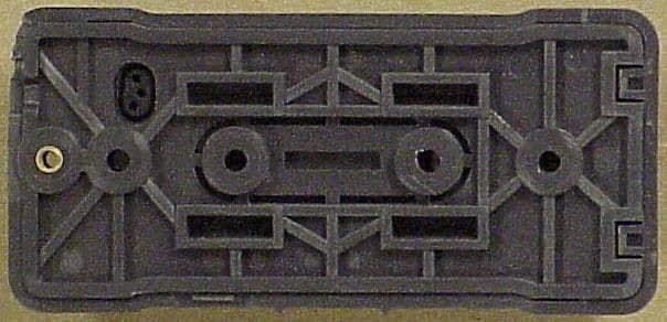
Click to zoom
Application Details
- Equipment Class
- DSC - Part 15 Security/Remote Control Transmitter
- Date of Grant
- Jul 13, 2010
- Application Purpose
- Original Equipment
- Date of Application
- Jul 13, 2010
- Equipment Note
- Door/Gate Security Transmitter
- Frequency Range
- 344.94000000 - 344.94000000
- Company
- Ademco Inc.
- Country
- United States
Documents & Files
Document Text
Text extracted from the exhibit documents filed with the FCC. Open a document above to read the original.
Users Manual
5816OD Wireless Outdoor Sensor – Quick Installation Guide For Online Support visit: http://www.security.honeywell.com/hsc/resources/MyWebTech/ General Information and Component Identification The Honeywell 5816OD Wireless Outdoor Sensor (referred to as the sensor) brings the convenience of wireless technology to the outdoors. The major features are: Weatherized security protection for an outdoor environment. Great for sheds, barns, garages, pool gates, fences, and rural mailbox (notifications). Versatile mounting options on flat and round materials. Cover and rear tamper detection. Can be painted to coordinate with mounting surface. Operating temp: – 40 to + 50° C (– 40 to +122° F) at RH of 100% (rain, snow). Magnet Gap (Wood): 2 inches Magnet Gap (Metal): 1.75 inches /no Magnet Spacer Magnet Gap (Metal): 2 inches /with Magnet Spacer COMPONENT IDENTIFICATION 5816OD-001-V0 SENSOR MOUNTING PLATE MAGNET MAGNET SPACER SENSOR BATTERY CHAMBER COVER Installing / Replacing the Batteries IMPORTANT: Change both batteries at the same time. Do not mix weak batteries with new batteries. Use two (2) lithium 1.5VDC AA cells. (For best life, use Eveready's Energizer Ultimate LITHIUM AA batteries, Honeywell part number 462) OBSERVE BATTERY POLARITY. Battery Replacement: 1. Remove cover screw and swing Sensor to remove from Sensor Mounting Plate . 2. Use screwdriver in any pivot point and pry Battery Chamber Cover off. Replace batteries. 3. Orient Battery Chamber Cover so the screw hole lines up with the screw hole in the sensor cover, and press to close. 4. Engage Sensor tabs into mating holes in Sensor Mounting Plate and swing closed. Secure with cover screw. 5816OD-002-V0 + + PRY POINTS TERMINAL BLOCK FOR EXTERNAL CONTACT SWITCH Mounting Guidelines Mount the Magnet on the magnet sensing side of the Sensor as indicated by the ribs on the Sensor. Mount Sensor on stationary surface, and Magnet on moveable surface. When used on wooden sheds and barns, mount the sensor and magnet on the inside of the structure. Use the Magnet Spacer when mounting on metal surfaces; or if needed to achieve proper alignment with Sensor . Flat Surfaces: Use screws suitable for the material being fastened to. FLAT SURFACES COVER SCREW MOUNTING SCREW (4) 5816OD-003-V0 MAGNET MAGNET SPACER MOUNTING SCREW (2) SENSOR SENSOR MOUNTING PLATE FENCE POST FENCE GATE Curved Surfaces: Mount using self locking stainless steel strap ties. 5816OD-005-V0 Self Locking Stainless Steel Strap Tie Alternately you can use extra heavy duty Nylon 6/6 UV and Temperature Rated cable ties (0.5 inch wide). If desired you may use screws in addition to the ties. CURVED SURFACES 5816OD-004-V0 MAGNET SENSOR GATE POST GATE MAGNET SENSING SLIDE COVER SCREW FENCE MAGNET SPACER SENSOR MOUNTING PLATE ROUTING EXTERNAL WIRING (Optional for use with external closed contact switches): Note: Use minimum of 22AWG jacketed cable. The contact switch must be a normally closed type. UL – The wired contact must be less than 3 feet from the transmitter. 1. Strip cable jacket back 4-inches to allow enough slack to remove Battery Chamber Cover when changing batteries. 2. Pass cable through the access hole in Sensor Mounting Plate. Use cable notch on mounting plate to pass jacketed portion of cable through. Then attach the Sensor Mounting Plate . 3. Route cable to the external contact switch and fasten at intervals to secure cable. 4. Remove the Battery Chamber Cover and thread wires through the rubber wire seal. 5. Connect wires to terminal block in battery chamber, and replace Battery Chamber Cover . (Note, orient the cover so the screw hole lines up with the screw hole in the sensor cover, and press to close.) 6. Engage Sensor tabs into Sensor Mounting Plate mating holes and swing closed. Secure with cover screw. SENSOR SENSOR MOUNTING PLATE BATTERY CHAMBER COVER 5816OD-006-V0 TO EXTERNAL CONTACT SWITCH CONNECT WIRES TO TERMINAL BLOCK IN BATTERY CHAMBER PAINTING THE SENSOR: The sensor and magnet may be painted to coordinate its color with the mounting surface. Use only paints that are made for plastic and follow the manufacturers directions for preparing the plastic and applying the paint. Note, the required drying and curing times. DO NOT USE METALLIC PAINT COLORS. Recommended Paints : Krylon® "Fusion for Plastic" Rust-Oleum® "Plastic" Dupli-Color® "Vinyl & Fabric Coating" Programming the Control Panel You must program the transmitter's serial number, input type (RF Supervised), response type, and loop # in the control panel. (Either or both loops may be used. Loop # 2 is for the magnet sensing, and Loop # 1 is for the external contact switch.) Refer to the control panel’s instructions for further details. Note: The transmitter's serial number may be found on the carton, and in the Battery Chamber. FCC/IC STATEMENT This device complies with Part 15 of the FCC Rules, and RSS 210 of IC. Operation is subject to the following two conditions: (1) This device may not cause harmful interference (2) This device must accept any interference received, including interference that may cause undesired operation. FCC STATEMENT The user shall not make any changes or modifications to the equipment unless authorized by the Installation Instructions or User's Manual. Unauthorized changes or modifications could void the user's authority to operate the equipment. WARRANTY For the latest warranty information go to: http://www.security.honeywell.com/hsc/resources/wa/ Ê800-04494UŠ 800-04494 11/09 Rev. A 2 Corporate Center Drive, Suite 100 P.O. Box 9040, Melville, NY 11747 Copyright 2009 Honeywell International Inc. www.honeywell.com/security
External Photos
EXHIBIT 4-1 CFS8DL5816OD / 573F-5816OD EXTERNAL PHOTOS TOP PLASTIC: BOTTOM PLASTIC:
ID Label/Location Info
EXHIBIT 8 CFS8DL5816OD / 573F-5816OD LABEL INFORMATION SECTION 2.1033 (c) and Part 15.21 SECTION 2.1033 (c) Label and label location - A photo showing the identification label clearly (you must be able to see the name and FCC ID number), and the location on the device. In lieu of a photo for this, you may submit a engineer’s drawing. Part 15.21 / SECTION 2.1033 (c Statement - for all intentional and unintentional radiators is also printed on the label. All devices shall bear the following statement in a conspicuous location on the device: “ This device complies with Part 15 of the FCC Rules and RSS 210 of Industry Canada. Operation is subject to the following two conditions: (1) this device may not cause harmful interference, and (2) this device must accept any interference received, including interference that may cause undesired operation. “ ENGINEERS DRAWING: EXACT LOCATION OF LABEL ON THE BOTTOM PLASTIC:
Internal Photos
EXHIBIT 4-2 CFS8DL5816OD / 573F-5816OD INTERNAL PHOTOS PCB PLASTIC: TOP OF PCB: BOTTOM OF PCB:
Test Report
EXHIBIT 5-1 CFS8DL5816OD / 573F-5816OD Report of Measurements . Measurements for the Intentional Radiator,and OBW were made in accordance with the procedures and reporting requirements at: Honeywell's OATS ( FCC No: 152762 & IC No:573F-1 ) which is located at: 2 Corporate Center Drive, Melville, NY 11747. Measurements were made in accordance with the procedure and reporting requirements of ANSI C63.4-2003. The Test Set-Up (C63.4 section 10.1.3) is shown in EXHIBIT 5-2; "Test Setup Photos". The sequence of testing (C63.4 section 10.1.7) for radiated emissions is as follows: A preliminary scan was conducted with the receiver antenna close to the EUT in order to identify the emission characteristics of the EUT (C63.4 section 8.3.1.1). The antenna and EUT were then placed at the proper separation ( 3 Meters) with the EUT positioned at 80 cm on a non-conducting turntable. The EUT was rotated on the turntable to maximize the received signal strength, then the receiver antenna height was varied between one (1) and four (4) Meters to further maximize the received reading. Thereafter, the device was again rotated to a peak output position and the antenna height wa s re-adjusted for maximum received signal. This procedure was re-iterated until there was no further increase in signal level. This procedure was performed with the EUT rotating in three orthogonal planes (C63.4 section 13.1.4.1) to generate a final maximum reading which is recorded on the radiated emissions result sheet. Similar measurements were made on the receiver to ensure compliance as an unintentional radiator. Note, The Spectrum Analyzer resolution bandwidths set as follows; (Video Bandwidth is always set 3X greater than RBW) For occupied bandwidth measurements, RBW = 30KHz and VBW = 100KHz. For radiated emissions below 1 GHz, the RBW = 100kHz. Detector function set to peak. For radiated emissions above 1 GHz, the RBW = 1MHz. Detector function set to peak. TRANSMITTER RADIATED EMISSIONS are recorded in "EXHIBIT 5-3". OCCUPIED BANDWIDTH is recorded in "EXHIBIT 5-4". TEST EQUIPMENT ( per C63.4 section 10.1.4) is recorded in "EXHIBIT 6".
Test Report
HONEYWELL SECURITY & CUSTOM ELECTRONICSREV K FEB 10 2 Corporate Center Drive Melville, NY 11747EXHIBIT 5-3FCC ID:CFS8DL5816OD Date : 06/28/2010 Tested by : G. BARBATO Approved by : K. Eskildsen Test Sample (model) : 344.94 MHz 5816OD Test method: ANSI C63.4 - 2004 Test specification: FCC Part 15, Sub-part C and RSS 210 , Issue 7 Notes: (1) Fo = 34 4.94 MHz. (2) Detector = Peak (3) Frequency range scanned to 4 GHz. Emissions not reported were more than 20dB below the specified unit. [(Meter reading + Cable/Amp factor + Antenna factor) / 20 )] (4) Conv. Reading = 10 (5) Corr. Reading = Conv. Reading X Duty Cycle (6) Six Highest Emissions Recorded Freq. (MHz) Antenna Polarity (V/H) Meter Reading (dB uV) Cable/Amp Factor (dB) Antenna Factor (dB/m) Conv. Reading (uV/M) Duty Cycle (%) Corr. Reading (uV/M) Limit @ 3M (uV/M) 30 LAST CAL 16 FEB 09 CABLE C LAST CAL 10 JUL 09 BICONILOG S/N:00045682 729 344.94v79.212.314.3762230.010.0%6223.07292 689.88v36.153.219.66892.310.0%89.2729 1034.82v28.344.425.22790.710.0%79.1500 1379.76v28.294.926.35948.410.0%94.8500 1724.70v20.925.527.49496.010.0%49.6729 2069.64v24.206.431.341250.310.0%125.0729 2414.58v21.396.931.811011.610.0%101.2729 2759.52 v 22.207.4 31.561142.910.0%114.3500 3104.46v23.377.932.341515.310.0%151.5729 3449.40v24.319.233.092138.010.0%213.8729 4000 LAST CAL 16 FEB 09 CABLE C LAST CAL 10 JUL 09 BICONILOG S/N:00045682
Test Report
EXHIBIT 5-4 OCCUPIED BANDWIDTH CFS8DL5816OD / 573F-5816OD 5816OD OBW: 200.4 KHz
Test Report
EXHIBIT 6 TEST EQUIPMENT USED CFS8DL5816OD / 573F-5816OD Section 15.231 and ANSI C63.4 This is a list of all test equipment used. Test Equipment list for Honeywell OATS: Equipment Mfg Model Cal Date Cal Due Spectrum Analyzer Rohde & Schwarz FSEA20 10/12/09 10/12/10 Antenna (‘Biconilog’) ETS (EMCO)Lindgren 3149 07/10/09 07/10/10 PLEASE SE E PAGE 2-6 FOR TEST EQUIPMENT TRACEABILITY If you need any additional information from Honeywell please contact: Greg Barbato RF Engineer (Acting for Ken Eskildsen) Phone (Direct): (516) 577-5863 Email: [email protected] I . : l:,irli r::::t::i.:,44i.,,i .: i:. illlil.,. lssue Date: 1011212009 Performed Bv: GENERAL CALIBRA-NON. INC. 2 MARS COURT MONTVILLE, NJ 07045 Equipmentlnformation ii '" ,:: Job No.: 018675 Manufacturer: R&S Description: SPECTRUM ANALYZER Deoartment: ALARMNET Temp./RH: 22 Ct45% Cal. Interval: 12 MONTHS CalDate:10t12t2009 Calibration Notes Company GENERALCALIBRATION 1031 GENERALCALIBRATION 434 GENERALCALIBRATION 650 GENERALCALIBRATION 774 GENERALCALIBRATION 967 General Calibration, Inc. 2 Mars Court, Boonton, New Jersey 07005 Phone (973) 299-2950 Fax (973) 299-0595 Asset Tag No.: MqdqlNumber: SerialNumber: Inspected By: Job Title: Calibration Result: Cal. Due Date: Certificate #: 15395MR Purchase Order: 5105648 Work Order #: MR309 Gustomer #: 001464 Location of Calibration: HONEYWELL SECURTTY (001464) 2 CORPOMTE CENTER DRIVE MELVILLE, NY 11747 10506 FSEA2O DE23427 MR::I METROLOGIST PASS 10t12t2010 Cal. Duo Date 02t02t2010 09t18t2010 12t08t2009 07 t13t2010 09t15t2010 Condition: Found In Tolerance and Lett In Tolerance Proceduro #GGP: R&S F$EA20 Standards Used To Calibrate Equipment | , ,,,' , ;,-',, r.D. SYNTHESIZED SWEEPER POWER SPLITTER POWER SPLITTER POWER SENSOR FUNCTION GENERATOR The above instrument has been checked and calibrated against the above working standard(s) which are traceable to the NIST. The test limits stated in the report correspond to the published specifications of the equipment, at the points tested. Afso, the collective uncertainties of measurement standards do not exceed 25o/o of lhe tolerance of the characteristics being caliprated, wlere possible. The metrology procedures utilized conform to and satisry the requirements set forth in ANSYNCSL 2540-1-1994,10 cFR part 21, lso 9001-2000, tso 10012-2003. and MtL-srD 4s662A. Approved By. General Calibration, Inc. - Q. A. Manaqer Page +of 1 This cedifcate is not a contrad. We are not responsible for any damages resulting from the use ofthese standards by the customel This cedificate shall not be reproduced, except in tull, without the witen notification ofceneral Calibralion: Inc.
Test Setup Photos
EXHIBIT 5-2 PICTURES OF THE 5816OD UNDER TEST CFS8DL5816OD / 573F-5816OD SENSE ANT HORZ., UUT FORWARD SENSE ANT HORZ., UUT FORWARD SENSE ANT HORZ., UUT FORWARD SENSE ANT VERT., UUT FORWARD SENSE ANT VERT., UUT FORWARD SENSE ANT VERT., UUT FORWARD PICTURE OF THE HONEYWELL OATS AT: 2 CORPORATE CENTER DRIVE MELVILLE, NY 11747
Contact Information
Applicant
Christian Fouth(Sr. Wireless Certification Engineer)
Technical Contact
Honeywell International, Inc.Kenneth Eskildsen
[email protected]516-577-5878
2 Corporate Center Drive · Melville, New York · United States
Test Firm
Honeywell International Inc.Mark Schmidt
Technical Specifications
| # | Rule Parts | Frequency Range | Power Output |
|---|---|---|---|
| 1 | 15.231 | 344.94 MHz - 344.94 MHz | - |
Other Applications from Ademco Inc.

CFS8DL5800MINIV
Jan 28, 2026Wireless Alarm Transmitter
Equipment Class
DXX - Part 15 Low Power Communication Device Transmitter
CFS8DLWTS800
Jan 12, 2026Wireless Alarm Transmitter
Equipment Class
DTS - Digital Transmission SystemCFS8DLCAMWEWI1
Jul 25, 2024VX5 HD Indoor Camera
Equipment Class
DTS - Digital Transmission System
CFS8DLCAMWEWO1
Sep 17, 2023VX3 HD Outdoor Camera
Equipment Class
NII - Unlicensed National Information Infrastructure TX
CFS8DLLMD500A
Jul 20, 2023Wireless door/window contact
Equipment Class
DTS - Digital Transmission System