CFS8DL5816XT2Wireless Door/Window Transmitter
Ademco Inc.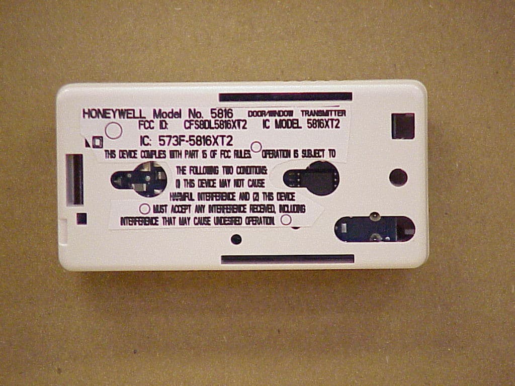
Click to zoom
Application Details
- Equipment Class
- DSC - Part 15 Security/Remote Control Transmitter
- Date of Grant
- Feb 03, 2010
- Application Purpose
- Original Equipment
- Date of Application
- Feb 03, 2010
- Equipment Note
- Wireless Door/Window Transmitter
- Frequency Range
- 344.94000000 - 344.94000000
- Company
- Ademco Inc.
- Country
- United States
Documents & Files
Document Text
Text extracted from the exhibit documents filed with the FCC. Open a document above to read the original.
Users Manual
5816XT2 ( TO BE SOLD AS OUR "5816" ) PAGE 1 We are moving from a “Paper Users Manual” to a “Web-Based Users Manual”. In order to do this there will be a ‘quick-start users manual’ printed on the 5816 carton, here is the outside carton art, please note that the outside art also carries the FCC / IC Regulatory Statements: 5816XT2 ( TO BE SOLD AS OUR "5816" ) PAGE 2 When you unfold the 5816 carton you see the interior text and art. If you look at the left most panel you will see the link to the “Web-Based Users Manual” printed on the 5816 carton artwork: 5816XT2 ( TO BE SOLD AS OUR "5816" ) PAGE 3 The link that is printed on the 5816 carton artwork is: (For the purpose of this Permissive change please cut & paste this link into Your browser:) http://www.security.honeywell.com/hsc/resources/MyWebTech Go to this site, then... 1. Click on "Go To MyWebTech" 2. Enter the login credentials: Your Login is: honeywell Your password is: support99 NOTE: Users who do not have login credentials are assigned login credentials at the ‘MyWebTech’ Site. 3. Enter "5816" in the Search By/My Product field (upper left corner of screen), then click "Go" 4. Click the "Install Instructions" link beneath the product picture that appears. (your browser needs to be configured to allow popup windows, OR right-click on the link and select "Open Link in New Window.") 5. You will then see a pfd of the full Users Manual. The Next two (2) pages contain the Full Users Manual for Your comparison. N6482V2 4/98 Rev. C ADEMCO 5816 Door/Window Transmitter INSTALLATION AND SETUP GUIDE CASE HOLDING POSTS (2) PLATE MOUNTING HOLES (2) CONCEALED WIRING ENTRY HOLE CASE LOCKING TA B MAGNET ALIGNMENT STRIP 5816-002-V0 Diagram 1. Mounting Plate + – COVER PRY-OFF POINT ANTENNA HOLES "A" (2) (SEE TEXT) LOCKING TAB RELEASE WINDOW BATTERY REED SWITCH (INPUT 2) COVER TAMPER SWITCH COVER HOLDING HOOKS (2) A BREAKOUT FOR SURFACE WIRING SLOT FOR CONCEALED WIRING ACCESS ALIGN MAGNET WITH MARKS ON CASE AND GUIDE ON MTG. PLATE MAGNET (OBTAIN SEPARATELY) LOOP TERMINALS (INPUT 1) A NOTE 5816 HAS 2 UNIQUE ZONES 1/2” MAX. 5816-001-V0 Diagram 2. Transmitter, Cover Removed GENERAL INFORMATION The 5816 Door/Window Transmitter has its own unique serial number permanently assigned during manufacture. You must “enroll” the transmitter serial number in the control prior to its usage in the system. Refer to the control unit’s installation instructions for further details. Note: During programming of the control unit, 5816 transmitters shall be treated as “RF” (i.e., supervised RF) Type (mandatory for UL installations). The 5816 has two unique zones; the first is for a wired closed circuit contact loop and the second for its built-in reed switch (used in conjunction with a magnet as described below). Either or both zones may be used. For UL installations, a contact may not be more than 3 feet from the transmitter. A built-in cover tamper switch is activated when the cover is removed. INSTALLATION Mounting For proper orientation of the unit in relation to the mounting plate, loop wiring, and/or magnet, read all of this section before installing the unit. The description that follows assumes that the unit will be mounted as shown in the diagrams, with the magnet (if used) located to the unit’s right. The unit may, however, be installed in any direction, as long as the relationship of the unit to its mounting plate and (if used) magnet is maintained. Although two holes are provided in the unit that would permit mounting directly to a surface (holes ‘A’ in Diagram 2) it is recommended that the mounting plate be used, for ease in removing the unit for servicing should it become necessary. Before mounting the transmitter permanently, conduct Go/No Go tests (see control’s instructions) to verify adequate signal strength and reorient or relocate the transmitter if necessary. 1. Remove the transmitter’s cover by inserting the flat blade of a small screwdriver into the pry-off slot at the end of the unit farthest from the cover’s decorative ribs, and twisting the blade. 2. Disengage the supplied mounting plate from the unit by inserting the blade of a small screwdriver into the locking tab release window (see Diagram 2) and pressing it against the locking tab (see Diagram 1) while sliding the plate downward along the case back. 3. If a wired contact loop is to be used with concealed wiring, feed the wires through the concealed wiring entry hole at one corner of the mounting plate. For surface wiring entry, a thin “breakout” area is provided in the case wall. Wiring can be run through this “breakout” in the case when attaching the case in step 5. 4. Install the mounting plate, with its case holding posts pointing up (in this example), in the location selected as described in the control unit’s installation instructions. Use the flat head screws supplied. 5. Attach the case back to the mounting plate by sliding the keyhole slots in the case back down onto the mounting plate’s case holding posts. The locking tab will click as the case back locks in place. 6. If the unit’s reed switch is to be used, mount a No. 5799 Magnet (or equivalent; obtain separately) adjacent to the alignment marks on the case and the mounting plate’s alignment strip (see Diagram 2). Wiring Connections With the battery still not inserted, connect the contact loop (if used) to the unit’s loop terminals (see diagram). The contact loop must use closed circuit devices. The loop response time is a nominal 100mSec. Note: If the contact loop is not to be used, no connection is needed across its terminals. BATTERY INSTALLATION/REPLACEMENT 1. Remove the transmitter’s cover (if it is not already off) as described in Mounting Step 1. 2. Observe correct polarity and insert the battery provided into the battery holder (see Diagram 2). Take care not to bend the antenna. Note: Replace battery only with: Panasonic CR123A, Duracell DL123A, Sanyo CR123A, or ADEMCO 466. 3. To replace the cover, engage the hooks along on…
Text truncated - open the document above for the full version.
External Photos
EXHIBIT 4-1 CFS8DL5816XT2 / 573F-5816XT2 EXTERNAL PHOTOS TOP PLASTIC: EXHIBIT 4-1 CFS8DL5816XT2 / 573F-5816XT2 EXTERNAL PHOTOS BOTTOM PLASTIC:
ID Label/Location Info
EXHIBIT 8 LABEL INFORMATION CFS8DL5816XT2 / 573F-5816XT2 SECTION 2.1033 (c) and Part 15.21 SECTION 2.1033 (c) Label and label location - A photo showing the identification label clearly (you must be able to see the name and FCC ID number), and the location on the device. In lieu of a photo for this, you may submit a engineer’s drawing. Part 15.21 & RSS 210 Statement - for all intentional and unintentional radiators is also printed on the label. All devices shall bear the following statement in a conspicuous location on the device: “ This device complies with Part 15 of the FCC Rules. Operation is subject to the following two conditions: (1) this device may not cause harmful interference, and (2) this device must accept any interference received, including interference that may cause undesired operation. “ PHOTO SHOWING EXACT LOCATION OF Part 15.21 & RSS 210 STATEMENT LABEL ON BOTTOM (BACK) PLASTIC: PLEASE LOOK AT PAGE 2 FOR THE ENGINEERS DRAWING
Internal Photos
EXHIBIT 4-2 CFS8DL5816XT2 / 573F-5816XT2 INTERNAL PHOTOS PCB IN PLASTIC: EXHIBIT 4-2 CFS8DL5816XT2 / 573F-5816XT2 INTERNAL PHOTOS TOP OF PCB: EXHIBIT 4-2 CFS8DL5816XT2 / 573F-5816XT2 INTERNAL PHOTOS BOTTOM OF PCB:
Test Report
EXHIBIT 5-1 CFS8DL5816XT2 / 573F-5816XT2 Report of Measurements . Measurements for the Intentional Radiator,and OBW were made in accordance with the procedures and reporting requirements at: Honeywell's OATS ( FCC No: 152762 & IC No:573F-1 ) which is located at: 2 Corporate Center Drive, Melville, NY 11747. Measurements were made in accordance with the procedure and reporting requirements of ANSI C63.4-2003. The Test Set-Up (C63.4 section 10.1.3) is shown in EXHIBIT 5-2; "Test Setup Photos". The sequence of testing (C63.4 section 10.1.7) for radiated emissions is as follows: A preliminary scan was conducted with the receiver antenna close to the EUT in order to identify the emission characteristics of the EUT (C63.4 section 8.3.1.1). The antenna and EUT were then placed at the proper separation ( 3 Meters) with the EUT positioned at 80 cm on a non-conducting turntable. The EUT was rotated on the turntable to maximize the received signal strength, then the receiver antenna height was varied between one (1) and four (4) Meters to further maximize the received reading. Thereafter, the device was again rotated to a peak output position and the antenna height wa s re-adjusted for maximum received signal. This procedure was re-iterated until there was no further increase in signal level. This procedure was performed with the EUT rotating in three orthogonal planes (C63.4 section 13.1.4.1) to generate a final maximum reading which is recorded on the radiated emissions result sheet. Similar measurements were made on the receiver to ensure compliance as an unintentional radiator. Note, The Spectrum Analyzer resolution bandwidths set as follows; (Video Bandwidth is always set 3X greater than RBW) For occupied bandwidth measurements, RBW = 30KHz and VBW = 100KHz. For radiated emissions below 1 GHz, the RBW = 100kHz. Detector function set to peak. For radiated emissions above 1 GHz, the RBW = 1MHz. Detector function set to peak. TRANSMITTER RADIATED EMISSIONS are recorded in "EXHIBIT 5-3". OCCUPIED BANDWIDTH is recorded in "EXHIBIT 5-4". TEST EQUIPMENT ( per C63.4 section 10.1.4) is recorded in "EXHIBIT 6".
Test Report
HONEYWELL SECURITY & CUSTOM ELECTRONICSREV K JAN 10 2 Corporate Center Drive Melville, NY 11747EXHIBIT 5-3FCC IDCFS8DL5816XT2 Date : 1/26/2010Tested by : Y. MohammedApproved by : K. Eskildsen Test Sample (model) : 5816XT2 Test method: ANSI C63.4 - 2004 Test specification: FCC Part 15, Sub-part C and RSS 210 , Issue 7 Notes: (1) Fo = 344.94 MHz. (2) Detector = Peak (3) Frequency range scanned to 4 GHz. Emissions not reported were more than 20dB below the specified unit. [(Meter reading + Cable/Amp factor + Antenna factor) / 20 )] (4) Conv. Reading = 10 (5) Corr. Reading = Conv. Reading X Duty Cycle (6) Six Highest Emissions Recorded Freq. (MHz) Antenna Polarity (V/H) Meter Reading (dB uV) Cable/Amp Factor (dB) Antenna Factor (dB/m) Conv. Reading (uV/M) Duty Cycle (%) Corr. Reading (uV/M) Limit @ 3M (uV/M) 30 LAST CAL 16 FEB 09 CABLE C LAST CAL 10 JUL 09 BICONILOG S/N:00045682 729 344.94v79.242.314.3762445.310.0%6244.57292 689.88h32.303.220.02597.010.0%59.7729 1034.82h28.604.424.85780.710.0%78.1500 1379.76h34.704.925.931890.210.0%189.0500 1724.70h36.805.526.962904.010.0%290.4729 2069.64h31.406.431.362870.810.0%287.1729 2414.58h27.306.932.152077.310.0%207.7729 2759.52 h 24.007.4 32.371543.510.0%154.3500 3104.46h24.00*7.932.731704.110.0%170.4729 3449.40h24.00*9.233.002041.710.0%204.2729 4000 NOTE: * = NOISE FLOOR LAST CAL 16 FEB 09 CABLE C LAST CAL 10 JUL 09 BICONILOG S/N:00045682
Test Report
EXHIBIT 5-4 5816XT2 CFS8DL5816XT2 / 573F-5816XT2 Occupied Bandwidth (200.4 KHz)
Test Report
EXHIBIT 6 TEST EQUIPMENT USED CFS8DL5816XT2 / 573F-5816XT2 Section 15.231 and ANSI C63.4 This is a list of all test equipment used. Test Equipment list for Honeywell OATS: Equipment Mfg Model Cal Date Cal Due Spectrum Analyzer Rohde & Schwarz FSEA20 10/14/08 10/14/09 Antenna (‘Biconilog’) ETS (EMCO)Lindgren 3149 07/10/09 07/10/10 PLEASE SEE PAGE 2- 3 FOR TEST EQUIPMENT TRACEABILITY If you need any additional information from Honeywell please contact: Greg Barbato RF Engineer (Acting for Ken Eskildsen) Phone (Direct): (516) 577-5863 Email: [email protected]
Test Setup Photos
EXHIBIT 5-2 PICTURES OF THE TEST SETUP CFS8DL5816XT2 / 573F-5816XT2 SECTION 2.1093 (c) Photo of the test setup shall be provided. HONEYWELL’S OATS MEASUREMENT FACILITY AT: 2 CORPORATE CENTER DRIVE MELVILLE, NY 11747 SENSE ANT: HORZ, UUT VERT SENSE ANT: HORZ, UUT HORZ SENSE ANT: HORZ, UUT OBLQ SENSE ANT: VERT, UUT VERT SENSE ANT: VERT, UUT HORZ SENSE ANT: VERT, UUT OBLQ
Contact Information
Applicant
Christian Fouth(Sr. Wireless Certification Engineer)
Technical Contact
Honeywell International Inc.Kenneth Eskildsen
[email protected]516-577-5878
2 Corporate Center Drive · Melville, New York · United States
Test Firm
Honeywell International Inc.Mark Schmidt
Technical Specifications
| # | Rule Parts | Frequency Range | Power Output |
|---|---|---|---|
| 1 | 15.231 | 344.94 MHz - 344.94 MHz | - |
Other Applications from Ademco Inc.

CFS8DL5800MINIV
Jan 28, 2026Wireless Alarm Transmitter
Equipment Class
DXX - Part 15 Low Power Communication Device Transmitter
CFS8DLWTS800
Jan 12, 2026Wireless Alarm Transmitter
Equipment Class
DTS - Digital Transmission SystemCFS8DLCAMWEWI1
Jul 25, 2024VX5 HD Indoor Camera
Equipment Class
DTS - Digital Transmission System
CFS8DLCAMWEWO1
Sep 17, 2023VX3 HD Outdoor Camera
Equipment Class
NII - Unlicensed National Information Infrastructure TX
CFS8DLLMD500A
Jul 20, 2023Wireless door/window contact
Equipment Class
DTS - Digital Transmission System