CFS8DL5817CBXTWireless Contact-Monitoring TX
Ademco Inc.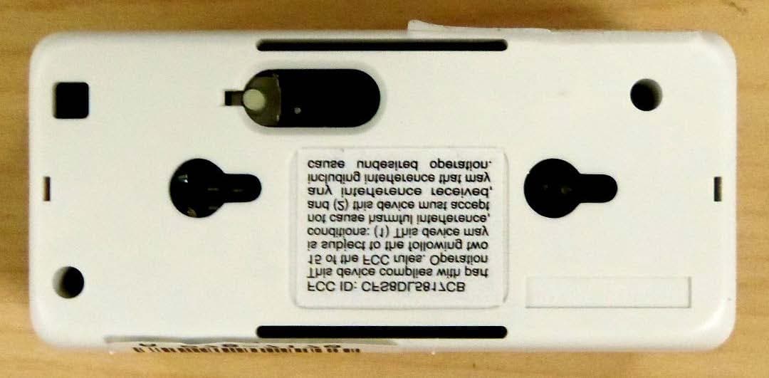
Click to zoom
Application Details
- Equipment Class
- DXX - Part 15 Low Power Communication Device Transmitter
- Date of Grant
- Jul 20, 2014
- Application Purpose
- Original Equipment
- Date of Application
- Jul 20, 2014
- Equipment Note
- Wireless Contact-Monitoring TX
- Frequency Range
- 344.94000000 - 344.94000000
- Company
- Ademco Inc.
- Country
- United States
Documents & Files
Document Text
Text extracted from the exhibit documents filed with the FCC. Open a document above to read the original.
Users Manual
ADEMCO 5817CBXT Wireless Commercial/Household Transmitter Installation Instructions General Information The 5817CBXT is a universal contact-monitoring transmitter that can be used with household and commercial fire and burglary-initiating devices such as door/window contacts, motion and glassbreak detectors, sprinkler water flow switches, tamper switches, post indicator valves, manual pull stations, and remote duct detectors. The 5817CBXT has three unique input loops (zones). Loop 1: Supervised and typically used for high-priority alarm reporting such as commercial fire or burglary. It requires a 470K ohm end-of-line resistor (PN EOLR 470K) to be placed across the sensor. Short circuit reports as loop 1; open circuit reports as loop 4 (tamper). Response time is 50mS. Loop 2: Built-in, normally closed reed switch (used in conjunction with a magnet). Loop 3: Normally closed household burglary loop. Response time is 80mS. Loop 4: Tamper loop (automatically enrolled) contains two tamper switches. A built-in cover tamper switch is activated when the cover is removed. A unit tamper switch is activated if the unit is separated from its mounting plate. 1 Programming The 5817CBXT has a built-in serial number that must be enrolled in the control panel prior to its usage in the alarm system. Assign loops 1-3 to individual zones respectively. Refer to the control panel's installation instructions for specific programming procedure. When programming the 5817CBXT transmitter, set as Input Type "RF" (i.e., supervised RF) (mandatory for UL installations). NOTE: DIP switch 1 must be set to OFF during enrollment. 2 Mounting • Signal strength may vary from location to location. Before mounting the transmitter permanently, conduct Go/No Go tests (see control's instructions) to verify adequate signal strength from this location. • When a satisfactory location is found, remove the battery and proceed with installation. IMPORTANT: Do not mount the transmitter on or near metal objects, as this may affect transmission range. It is also good practice to avoid locating the transmitter near wiring such as AC, telephone, HVAC, computer data cables, etc. 1. Remove the tamper switch hold down tab from the mounting plate and set it aside. It will be needed if not using the mounting plate. 2. Remove the transmitter's cover using the flat blade of a small screwdriver in the pry-off slot and twisting. To replace the cover, engage the hooks along the top edge and snap shut. 3. Disengage the mounting plate from the case back by inserting the blade of a small screwdriver into the mounting plate release hole (see Figure 3) and pushing the locking tab out (see Figure 1). Slide the mounting plate downward along the case back. 4. For Concealed Wiring: Feed the wires through the concealed wiring entry hole at the bottom corner of the mounting plate (and/or case back). For Surface Wiring: Remove the knockout slot in the case back (near loop 3 terminal block). Do not connect the wiring to the terminal block(s) yet. 5. If Using the Mounting Plate ( for easy removal later for servicing): a. Install the mounting plate in the location determined, with its case - holding posts pointing up. Use two flat head dry-wall screws. NOTE: To ensure proper operation of the unit's back tamper, the screws must be anchored to a wall stud or other solid wood material. b. Attach the case back to the mounting plate by sliding the keyhole slots in the case back down onto the mounting plate's holding posts. The locking tab clicks as the case back locks in place. If Not Using the Mounting Plate: a. Make note of the location of the tamper switch hold-down as shown in Fig. 1 for the proper placing of the hold-down tab in Fig. 2. b. Remove the PC board from the case back. Slide a small flat bladed screwdriver between the case back and PC board near the board hold-down clip and carefully pry the board out. c. In the area that was marked, install the hold-down tab with a 5/8” flat head dry-wall screw. The tab must be aligned with the corresponding slot in the case back as shown in Figure 2. The tab as well as the case back must be anchored to a wall stud or other solid wood material. Figure 1. Mounting Plate Figure 2. Case Back Figure 3. 5817CBXT Transmitter, Top Cover Removed NOTE: For UL commercial and household fire installations, only one initiating device may be connected to this transmitter. For UL commercial burglary installations, multiple initiating devices may be used as long as the devices all serve the same function, such as door/window contacts, motion or glassbreak detectors. All initiating devices must be located within the same room. No more than one wire per terminal may be connected. Use only 14-22AWG wire. d. Mount the case back to the wall using two flat head dry-wall screws, anchoring it to a wall stud or other solid wood material. e. Reinstall the PC board into the case back, position the board onto the two retaining studs on one side of the case back and snap the board into place. The hold- down tab must mate with the corresponding cutout in the case back after case back is installed. 6. Set the DIP switch (after the control panel has enrolled the transmitter loops) for the desired primary loop characteristics, as described in the Primary Loop Options Table. NOTES: • The DIP switch may be set by the installer only. It is not a user function. • Due to FCC regulation 15.231(a)(4), this switch may not be set to ON unless loop 1 is used to indicate a type of emergency involving fire, security, or safety of life. PRIMARY LOOP OPTIONS TABLE SWITCH SET TO DIP SWITCH POSITION ON REPEATING TRANSMISSION (every 4 sec.) UPON PRIMARY LOOP 1 FAULT Use for high priority alarm, such as fire. OFF SINGLE TRANSMISSION PER PRIMARY LOOP CHANGE-OF-STATE Notes: a. In order for the control panel to enroll the transmitter, DIP switch 1 must be set to OFF (see Figure 3). b. The Auxiliary loops are not affected by the DIP switch settings. 5 Testing Regular mainten…
Text truncated - open the document above for the full version.
External Photos
EXHIBIT 4-1 CFS8DL5817CBXT / 573F-5817CBXT 5817CBXT EXTERNAL PHOTOS CASE EXTERIOR Page 1 of 3 EXHIBIT 4-1 CFS8DL5817CBXT / 573F-5817CBXT 5817CBXT EXTERNAL PHOTOS CONT. CASE EXTERIOR CONT.h Page 2 of 3 EXHIBIT 4-1 CFS8DL5817CBXT / 573F-5817CBXT 5817CBXT EXTERNAL PHOTOS CONT. MOUNTING PLATE Page 3 of 3
ID Label/Location Info
EXHIBIT 8 CFS8DL5817CBXT / 573F-5817CBXT LABEL INFORMATION EXACT LOCATION OF THE LABEL: CASE BACK ENGINEER'S DRAWING OF THE LABEL: Page 1 of 1
Internal Photos
EXHIBIT 4-2 CFS8DL5817CBXT / 573F-5817CBXT 5817CBXT INTERNAL PHOTOS CASE INTERIOR WITH PCA INSTALLED: CASE INTERIOR WITH PCA REMOVED: Page 1 of 2 EXHIBIT 4-2 CFS8DL5817CBXT / 573F-5817CBXT 5817CBXT INTERNAL PHOTOS CONT. PCA TOP: PCA BOTTOM: Page 2 of 2
Test Report
EXHIBIT 5-1 CFS8DL5817CBXT / 573F-5817CBXT REPORT OF MEASUREMENTS Measurements for the Intentional Radiator,and OBW were made in accordance with the procedures and reporting requirements at: Honeywell's OATS ( FCC No: 152762 & IC No:573F-1 which is located at: 2 Corporate Center Drive, Melville, NY 11747 Measurements were made in accordance with the procedure and reporting requirements of ANSI C63.4- 2003. The Test Set-Up (C63.4 section 10.1.3) is shown in EXHIBIT 5-2: "Test Setup Photos". The sequence of testing (C63.4 section 10.1.7) for radiated emissions is as follows: A preliminary scan was conducted with the receiver antenna close to the EUT in order to identify the emission characteristics of the EUT (C63.4 section 8.3.1.1). The antenna and EUT were then placed at the proper separation ( 3 Meters) with the EUT positioned at 80 cm on a non-conducting turntable. The EUT was rotated on the turntable to maximize the received signal strength, then the receiver antenna height was varied between one (1) and four (4) Meters to further maximize the received reading. Thereafter, the device was again rotated to a peak output position and the antenna height was re-adjusted for maximum received signal. This procedure was re-iterated until there was no further increase in signal level. This procedure was performed with the EUT rotating in three orthogonal planes (C63.4 section 13.1.4.1) to generate a final maximum reading which is recorded on the radiated emissions result sheet. Similar measurements were made on the receiver to ensure compliance as an unintentional radiator. Note: The Spectrum Analyzer resolution bandwidths were set as follows: (Video Bandwidth is always set 3X greater than RBW) For Short Range Radio occupied bandwidth measurements, RBW = 30KHz and VBW = 100KHz. For radiated emissions below 1 GHz, the RBW = 100KHz. Detector function set to peak. For radiated emissions above 1GHz, the RBW = 1MHz. Detector function set to peak. TRANSMITTER RADIATED EMISSIONS are recorded in "EXHIBIT 5-3 ". OCCUPIED BANDWIDTH is recorded in "EXHIBIT 5-4". TEST EQUIPMENT (per C634. section 10.1.4) is recorded in "EXHIBIT 6". Page 1 of 1
Test Report
EXHIBIT 5-3 CFS8DL5817CBXT / 573F-5817CBXT SHORT RANGE RADIO RADIATED EMISSIONS HONEYWELL SECURITY & CUSTOM ELECTRONICS REV 07/23/2013-O 2 Corporate Center Drive Melville, NY 11747 EXHIBIT 5-3 FCC ID: CFS8DL 5817CBXT Date : 10-Mar 2014 Tested b Eduardo Sayers Approved by: Mark Schmidt Test Sample (model): 5817CBXT Test method: ANSI C63.4 - 2003 Test specification: FCC Part 15, Sub-part C and RSS 210 , Issue 8 PRESCAN: SENSE / UUT: EL (cm): AZ ( Meter Reading (dB uV): Notes: V/V 148.7 63.8 79.24 (1) Fo: 344.94 MHz H/V 122.6 138.1 70.17 (2) Detector = Peak V/H 194.5 360.0 71.74 (3) Frequency range scanned to 4 GHz. ( Emissions not reported were m 20dB below the specified unit ). H/H 100.0 274.0 76.13 (4) Conv. Read. = 10 [(Meter reading + Cable/Amp factor + Antenna fa )] V/O 131.0 178.0 76.47 (5) Corr. Reading = Conv. Reading X Duty Cycle H/O 100.0 100.0 75.23 (6) Six Highest Emissions Recorded Freq. (MHz): Sense Antenna Polarity (V/H): THE ORENT OF THE UUT (V,H, Meter Reading (dB uV): Cable/A Factor (dB): Antenna Factor (dB/m): Conv. Rea (uV/M): Duty Cycle (%): Corr. Rea (uV/M): Limit @ 3M (uV/M): 344.94 V V 79.24 2.5 14.92 68,076.9 10.0% 6807.7 7,289 689.88 V V 33.44 3.7 20.10 729.5 10.0% 72.9 729 1034.82 V V 40.31 4.7 24.82 3,101.0 10.0% 310.1 500 1379.76 V V 28.94 5.6 26.50 1,128.5 10.0% 112.8 500 1724.70 V V 29.06 6.3 29.00 1,644.4 10.0% 164.4 729 2069.64 V V 27.13 7.3 30.78 1,811.3 10.0% 181.1 729 2414.58 V V 27.74 8.1 32.16 2,500.3 10.0% 250.0 729 2759.52 V V 25.90 8.6 31.84 2,077.3 10.0% 207.7 500 3104.46 V V 27.46 9.1 32.13 2,721.1 10.0% 272.1 729 3449.40 V V 23.82 10.0 33.85 2,409.9 10.0% 241.0 729 LAST CAL JULY-14 BICONILOG S/N:0002939 Page 1 of 1
Test Report
EXHIBIT 5-4 CFS8DL5817CBXT/ 573F-5817CBXT SHORT RANGE RADIO (SRR) OCCUPIED BANDWIDTH RBW = 30KHz VBW = 100KHz OBW = 209.936KHz Page 1 of 1
Test Report
EXHIBIT 6A CFS8DL5817CBXT / 573F-5817CBXT TEST EQUIPMENT USED Part 15.231, ANSI C63.4, RSS 210 This is a list of all test equipment used. Note: Calibration Certificates are on following pages. Test Equipment list for Honeywell OATS & Conducted Line EQUIPMENT: MANUFACTURER: MODEL: CAL DATE: CAL DUE DATE: Spectrum Analyzer Rohde & Schwarz FSU3 5/9/2013 5/9/2014 Spectrum Analyzer Rohde & Schwarz FSU26 5/9/2013 5/9/2014 Antenna (“Biconilog”) ETS (EMCO) Lindgren 3149 7/8/13 7/8/14 If you need any additional information from Honeywell, please contact: Andrew Roussin, Engineer (Acting for Mark Schmidt) Phone (Direct): 516-577-5935 Email: [email protected] Page 1 of 4 Issue Date: 5/13lztl3 Description: ': . .l- t' SPECTRUM ANALYZER 2 Mars Court, Boonton, New Jersey 07005 Phone (973)299-2950 Fax (973) 299-0595 6i,1,,,' '.; 1.. Certificate #z 1034723 Work Order #: RH509 Customer #: 001464 ,,riiffi$' liffii'ti. ';$ '',;1,l,;;ii;'iiii'tffi;;ili:lil GENERAL CALIBRATION" INC. 2 MARS COURT BOONTON. NJ O7OO5 'iW Job No.: 06r,6ts Manufacturer: R&S liil ,:*'f.;,ffi,ffi1jii HONEYWELL SECURTry (001,164) 2 CORPORATE CENTER DRTVE ii,:,,,,,:,i.iu-\dt$.1..*4l;lliil! MELVILLE.NY 11747 .l i.Ll'.."'',= h;4p}:lffil..::::,',,,,;li;i1i Asset Tag_No1 Modgl Num-be,_r: iou iiii", ..'", : ,' l' ' . '': :r::i:i: '.'i' - l l:::,:il irrrrilii. t.rt i Department: remp.[t!: 22.0C1s3.0%1 Cal Interval: 12 MO,NTHS Cal Date: 0510912013 'linnn .# g=i Calibration Notes: Condition: Found In Tolerance and Left In Tolerance iiiillli ffiiffi il ', ", ::, ,,,;,iiiil'llr= G-E\TERAL CA-LTBRAIION 33s. . GENERAL CALIBRATION -q'9 FREQUENCY COTINTER GENERAL CALIBRATION 974 POWER METER C ali -b1pti oq_Re-su ltl lisu L ': .i:,i.;i'#i',. 1,"',,, .',,,, ,:,5 tnto .,,.::-' 11493 psug 100029 RHI il/ETROLOGIST PASSED 05109120t4 36144001:J ust77e?42'.8 25r64040!3 5 1oo2:L 2709429063 .C'qlirp ##ft 08/02t20t4 07t06/21013 ."9s12y2013 06t!812013 06t04t20t3 ftis is to c€.tiry that G€neral CalibEtion,Inc. is A2LA accrexlited and that its calibration system is in compliance wjih ISO/IEC 17025-2005, ANSI NCSL 2540-1, ANSI NCSL Z540-3,andIso9001:2l.c8'Thetestlimitsstatedinthereportco[espondtotheMaIufactuercalibmtionandpubIishedsp€ciIicationsoftheequipmen!atthepointsted' calibrationofstandards;ref€r€ncestandardsandint€rmediatestandardsinthiscalibmtionhavebeencheckedandcalibmtedagainsttheabove\aorkingstandard(s)which traceable to the National Institute ofstandards and T€chnolory. Any accredited calibmtion under our A2LA scope of accreditation is denoted with A2LA accrcdited symbol on th€ calibmtion certificate. Ifthe certificate includes any unacdedited itsms calibrated, they are clearly marked as unzLccredit€d caliblEtion. ijest Uncetainti€s rcpr€s€rt expanded uncerteinties expressed at apFoximately the 95% confidence level using a coverago factor ofk=2. The r€sults documented in this certificate relate only to th€ it€n(s) calibrared or test€d. Approved By ,:4r' " "11),',-,a/A . ;j.,':-' ..:2....t. -.. General Calibration, Inc. - Q. A. Manager i :...:::t!ttea-;1:]::.,i: i;#lii$- This certificate shall not be reDio(reFioduced, except in full, without the Mitten notification of ceneral Calibration, Inc lssue Date: 5ll3l20l3 GENERAL CALIBRATION. INC. 2MARS COURT General Calibration, Inc. 2 Mars Court, Boonton, New Jersey 07005 Phone (97 3) 299 -2950 F ax (97 3) 299-0595 Certificate #: 1034725 WorkOrder#: RH509 Customer#: 001464 $ffi HONEYWELL SECURTTY (001464) 2 CORPORATE CENTER DRIVE MEL\IILLE.NY I1747 BOONTON.NJ 07005 Job No.: wl7 Asset Tas No.: n4% "![gn3-fpcJuL91; Description: R&S SPECTRLIMANALYNR \4qSsl"Ny-rn!-"-r," SerialNumber: 100303 RHl FSU26 ,?qlg:!p.*1: Inspected By: Ten-p,AIIi C-p-!,fnJerv{1 Cal Date: 22.0 C I 53.0% 12 MONTHS Job Title: METROLOGIST Calibration Result: PASSED 05t09t2013 GENERAL CALIBRATION 335 SYNTHESIZED SWEEPER. 5OGTZ 3614400157 GENERALCALIBRATION 676 LEVEL GENERATOR 2516404043 9t{9?/-?9"'1" 05t2U2013 GENERAL CALIBRATION 856FREQUENCY COTINTER 51002-5 06t28t2013 GENERAL CALIBRATION 874POWERSENSOR 3318A1597 r t0n8t2013 GENERALCALIBRATION 974 POWERMETER 2709A29063 06t04t2013 This is to certi$/ that General Calibration, Inc. is A2LA accredited and that its calibration system is in compliance with ISO/IEC17025-2005, ANSI NCSLZS4O-|, ANSI NCSL 2540-3, and ISO 9001 :2008. The test limits stated in the repoqt conespond to the Manufacturer calibration and published specifications of the equipment, at the points tested. Calibrationofstandards;referencestandardsandintermediatestandardsinthiscalibrationhavebeencheckedandcalibratedagainsttheaboveworkingstandard traceable to the National Institute of Standards and Technology. Any accredited calibration under our A2LA scope of accreditation is denoted with 42LA accredited symbol on the calibration certificate. Ifthe certificate includes any unaccredited items calibrated, they are clearly marked as unaccredited calibration. Best Uncertainties represent expanded.uncertainties expressed at approximately the 95% confidence level using a coverage factor ofk=2. The results documented in this certificate relate only to the jtem(s) calibrated or tested. Approved By ".d14.- .,-. "x1 ;i:z;,',n--.:....*' General Calibration, Inc. - Q. A. Manager
Test Report
2 Corporate Center Drive Melville, NY 11747 516-577-2000 5817CBXT Radiated Emissions Comparison (7-10-2014) 3 Meter Roof Site Radiated Emissions Report from 5817CBXT Unit, with cables (July 9, 2014) Freq. (MHz) Sense Antenna Polarity (V/H) THE ORENTATION OF THE UUT (V/H/O) Meter Reading (dBuV) Cable/Amp Factor (dB) Antenna Factor (dB/m) Conv. Reading (uV/M) Duty Cycle (%) Corr. Reading (uV/M) Limit @ 3M (uV/M) 345.00 V V 78.71 2.8 15.42 70,557.3 10.0% 7055.7 7,292 690.00 V V 33.67 4.5 19.90 796.1 10.0% 79.6 729 1035.00 V V 34.48 6.0 24.05 1,691.1 10.0% 169.1 500 1380.00 V V 23.12 7.0 26.58 679.9 10.0% 68.0 500 1725.00 V V 22.63 8.0 28.95 956.5 10.0% 95.7 729 2070.00 V V 21.48 8.9 30.43 1,101.2 10.0% 110.1 729 2415.00 V V 22.89 9.8 32.09 1,737.6 10.0% 173.8 729 2760.00 V V 22.08 10.9 32.03 1,785.2 10.0% 178.5 500 3105.00 V V 23.26 11.8 32.10 2,266.8 10.0% 226.7 729 3450.00 V V 22.19 12.2 33.76 2,564.2 10.0% 256.4 729 3 Meter Roof Site Radiated Emissions Report from 5817CBXT Unit, without cables (March 10, 2014) Freq. (MHz) Sense Antenna Polarity (V/H) THE ORENTATION OF THE UUT (V/H/O) Meter Reading (dBuV) Cable/Amp Factor (dB) Antenna Factor (dB/m) Conv. Reading (uV/M) Duty Cycle (%) Corr. Reading (uV/M) Limit @ 3M (uV/M) 344.94 V V 79.24 2.5 14.92 68,076.90 10.00% 6808 7,289 689.88 V V 33.44 3.7 20.1 729.5 10.00% 72.9 729 1034.8 V V 40.31 4.7 24.82 3,101.00 10.00% 310.1 500 1379.8 V V 28.94 5.6 26.5 1,128.50 10.00% 112.8 500 1724.7 V V 29.06 6.3 29 1,644.40 10.00% 164.4 729 2069.6 V V 27.13 7.3 30.78 1,811.30 10.00% 181.1 729 2414.6 V V 27.74 8.1 32.16 2,500.30 10.00% 250 729 2759.5 V V 25.9 8.6 31.84 2,077.30 10.00% 207.7 500 3104.5 V V 27.46 9.1 32.13 2,721.10 10.00% 272.1 729 3449.4 V V 23.82 10 33.85 2,409.90 10.00% 241 729 Comparison from Orig and New Report Unit without Cables Unit with Cables Δ dB Corr. Reading (uV/M) Corr. Reading (uV/M) 6807.7 7055.7 0.3 72.9 79.6 0.8 310.1 169.1 -5.3 112.8 68.0 -4.4 164.4 95.7 -4.7 181.1 110.1 -4.3 250.0 173.8 -3.2 207.7 178.5 -1.3 272.1 226.7 -1.6 241.0 256.4 0.5 Page 3 of 3
Test Setup Photos
EXHIBIT 5-2A TEST PHOTOS CFS8DL5817CBXT / 573F-5817CBXT Vertical / Vertical Vertical / Horizontal Vertical / Oblique Horizontal / Vertical Horizontal / Horizontal Horizontal / Oblique RADIATED EMISSIONS TEST SETUP HONEYWELL’S 3 METER OATS AT: 2 Corporate Center Drive,Melville, NY 11747
Contact Information
Applicant
Christian Fouth(Sr. Wireless Certification Engineer)
Technical Contact
Honeywell International Inc.Stanley Albrechtsen
[email protected]5165775860
2 Corporate Center Drive · Melville, New York · United States
Non-Technical Contact
Honeywell International Inc.Mark Schmidt
[email protected]5165775939
Test Firm
Honeywell International Inc.Mark Schmidt
Technical Specifications
| # | Rule Parts | Frequency Range | Power Output |
|---|---|---|---|
| 1 | 15C | 344.94 MHz - 344.94 MHz | - |
Other Applications from Ademco Inc.

CFS8DL5800MINIV
Jan 28, 2026Wireless Alarm Transmitter
Equipment Class
DXX - Part 15 Low Power Communication Device Transmitter
CFS8DLWTS800
Jan 12, 2026Wireless Alarm Transmitter
Equipment Class
DTS - Digital Transmission SystemCFS8DLCAMWEWI1
Jul 25, 2024VX5 HD Indoor Camera
Equipment Class
DTS - Digital Transmission System
CFS8DLCAMWEWO1
Sep 17, 2023VX3 HD Outdoor Camera
Equipment Class
NII - Unlicensed National Information Infrastructure TX
CFS8DLLMD500A
Jul 20, 2023Wireless door/window contact
Equipment Class
DTS - Digital Transmission System