CFS8DL5819APShock Processor Transmitter
Ademco Inc.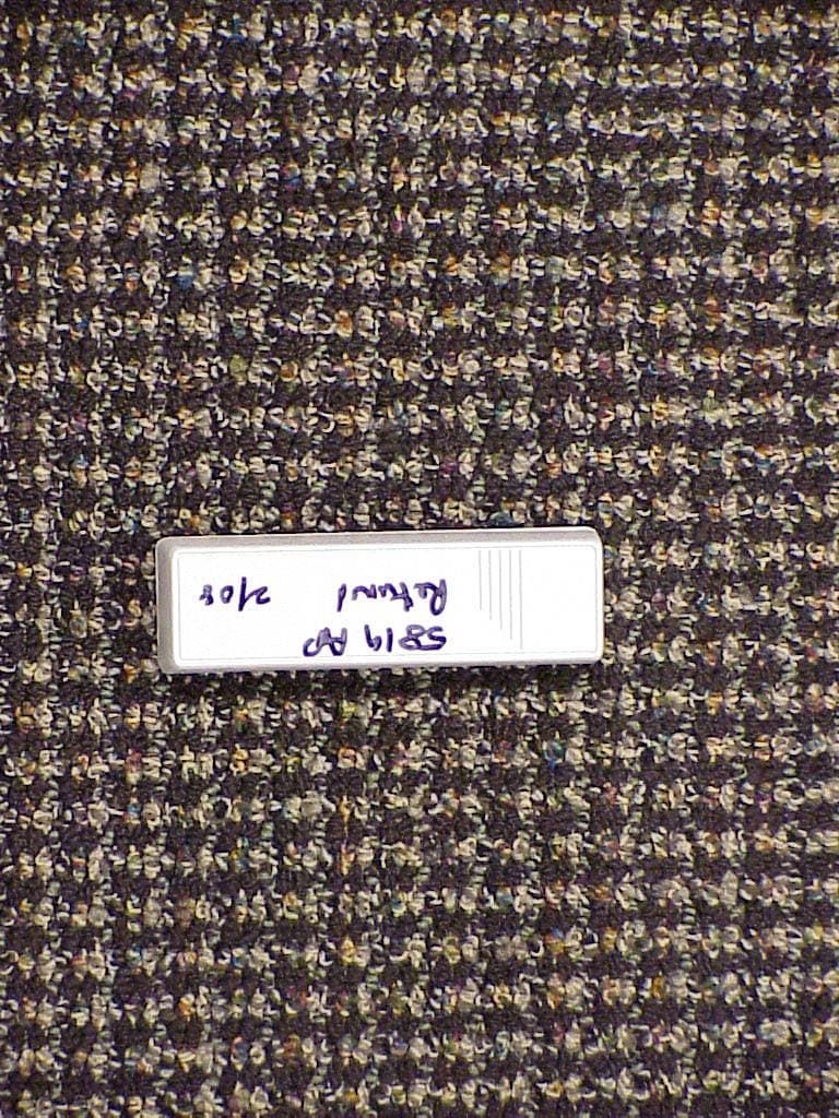
Click to zoom
Application Details
- Equipment Class
- DSC - Part 15 Security/Remote Control Transmitter
- Date of Grant
- Mar 17, 2008
- Application Purpose
- Original Equipment
- Date of Application
- Mar 17, 2008
- Equipment Note
- Shock Processor Transmitter
- Frequency Range
- 315.00000000 - 315.00000000
- Company
- Ademco Inc.
- Country
- United States
Documents & Files
Document Text
Text extracted from the exhibit documents filed with the FCC. Open a document above to read the original.
Users Manual
N7491-5 3/08 Rev. A 5819AP SHOCK PROCESSOR TRANSMITTER INSTALLATION AND SETUP GUIDE A + – BATTERY REED SWITCH (LOOP 2) COVER PRY-0FF POINT ALIGN MAGNET WITH MARKS ON CASE AND GUIDE ON MTG. PLATE MAGNET (OBTAIN SEPARATELY) LOOP 1 TERMINALS (See Detail “B”) LOCKING TAB RELEASE WINDOW COVER HOLDING HOOKS (2) COVER TAMPER SWITCH HOLES “A” (2) (SEE TEXT) ANTENNA DIP SWITCHES See Detail “A” DIP SWITCHES JUMPER PINS See Detail “B” SLOT FOR CONCEALED WIRING ACCESS A MAGNET Diagram 2: 5819AP (SHOWN WITH COVER REMOVED) 12" MAX 1 23 4 5 ON TB2TB1 MAGNETIC ALIGNMENT GUIDE STRIP RELEASE FOR BRACKET CASE HOLDING POSTS (2) SLOT FOR WIRE SCREW HOLES Diagram 1: MOUNTING PLATE TABLE 1 SWITCH RESPONSE TIME SW1 (Most Sensitive)1ms SW22ms SW35ms SW410ms SW5 (Least Sensitive) 20ms JUMPER PINS SHOCK SENSOR TERMINALS (INPUT LOOP 1) TABLE 2 JUMPER COUNT J1 (Most Sensitive)1 J22 J34 J46 J5 (Least Sensitive)8 J5 J4 J3 J2 J1 DETAIL B DETAIL A CONTACT TERMINALS (INPUT LOOP 3) LOOP 3 TERMINALS (See Detail “B”) 5819AP-001-V0 GENERAL INFORMATION The 5819AP Shock Processor Transmitter connects to inertia type shock detectors that are mounted externally to the transmitter case (detector not supplied), and is intended for use only with Honeywell alarm systems that support 5800 Series wireless devices. The 5819AP has three unique zones. The first is for a wired, normally closed shock sensor loop (TB1), the second is for a closed contact loop using the unit's built-in magnetic reed switch in conjunction with a magnet, and the third is for a wired closed circuit contact loop (TB2). The 5819AP has a built-in cover tamper switch that activates when the cover is removed. INSTALLATION Mounting For proper orientation of the unit in relation to the mounting plate, loop wiring, DIP switch adjustment, jumper positions, and/or magnet, read all of this section before installing the unit. The description that follows assumes that the unit will be mounted as shown in the diagrams, with the magnet (if used) located to the left of the unit. The unit can be installed in any direction, as long as the relationship of the unit to its mounting plate and (if used) magnet is maintained. Although two holes are provided in the unit that would permit mounting directly to a surface (holes "A" in Diagram 2), it is recommended that the mounting plate be used as described below, for ease in removing the unit for servicing should it become necessary. Before mounting the transmitter permanently, conduct Go/No Go tests (see control's instructions) to verify adequate signal strength and reorient or relocate the transmitter if necessary. 1. Remove transmitter's cover by inserting the flat blade of a small screwdriver into the pry-off slot nearest to the cover's decorative ribs, and twisting the blade. 2. Disengage the supplied mounting plate from the unit by inserting the blade of a small screwdriver into the locking tab release window (see Diagram 2) and pressing it against the locking tab (see Diagram 1) while sliding the plate downward along the case back. 3. If a shock processor or wired contact loop is to be used with concealed wiring, feed the wires through the concealed wiring entry hole at one corner of the plate. For surface wiring entry, a thin "breakout" area is provided in the case wall. 4. Install the mounting plate, with its case-holding posts pointing up (in this example), in the location selected. 5. Attach the case back to the mounting plate by sliding the keyhole slots in the case back down onto the mounting plate's case-holding posts. The locking tab will click as the case back locks in place. 6. If the unit's REED SWITCH is to be used, mount a 5799 Magnet (obtained separately) adjacent to the alignment marks on the case and the mounting plate's alignment strip (see Diagram 2). 7. Set response time (from Table 1) using the DIP switches. SW1 sets a response time of 1mS. SW5 sets a response time of 20mS. For a response time of 0.5mS, set all DIP switches to OFF (as shown in DETAIL A in Diagram 1 above). 8. Set the pulse count jumper (see Table 2). The pulse count is reset 3-seconds after the first pulse is detected. There is an LED on the PCB that flashes rapidly on transmission. Note: Make the device highly sensitive for the purpose of enrolling the shock sensor loop (TB1) into the system (turn SW1 on and put jumper on J1). After the device has been enrolled, adjust settings as described in steps 7 and 8 (above). WIRING CONNECTIONS With the battery still not inserted, connect the shock processor loop (if used) to the unit's loop TB1 terminals (see Detail "B"). The contact loops must use closed circuit devices. TB2 can be used for normally closed contacts. Note: If the contact loops are not used, no connection is needed across their terminals. "ENROLLING" THE TRANSMITTER SERIAL NUMBER Each 5819AP Shock Processor has its own unique serial number permanently assigned during manufacture. Each input of the transmitter also has a distinct "loop" number that must be input to the control panel during installation. Assign each to an individual zone and designate the Input Type as "RF" (Supervised RF). The serial number can be input by one of the following methods: • "Enrolled" by transmitting from the device during zone programming (pressing the tamper switch, shorting any loop, etc.). • Entered through the keypad at the "Input S/N" or "Transmit Now" prompt during manual zone programming. • Entered through COMPASS Downloading Software and downloaded to the control. When programming the 5819AP transmitter's serial number at the control panel, do the following: 1. At the "Input Type" prompt, enter "3" for RF (Supervised RF). 2. When prompted for the loop number, enter the input loop you are using (see Diagram 2). See the control panel's installation instructions for specific programming procedures. BATTERY INSTALLATION/REPLACEMENT 1. Remove the transmitter's cover as described in Mounting, Step 1. 2. Observe correct polarity and insert the battery pr…
Text truncated - open the document above for the full version.
Block Diagram
EXHIBIT 2-2 BLOCK DIAGRAM CFS8DL5819AP / 573F-5819AP SECTION 2.1033(b) (3) Block Diagram. Honeywell SAW Controlled Discreet Transmitter.
Operational Description
EXHIBIT 1 FUNCTIONAL DESCRIPTION CFS8DL5819AP / 573F-5819AP SECTION 2.1033(b) SECTION 2.1033(b) (2a). For Part 15 a brief description of the circuit functions of the device. The 5819AP is a wireless shock processor and transmitter. It processes mechanical shock events from inertia sensors (such as a door kick-in) and sends a standard 5800 type message to the panel via a 5881AP receiver. EXHIBIT 2-1 CIRCUIT DESCRIPTION CFS8DL5819AP / 573F-5819AP SECTION 2.1033(b) SECTION 2.1033(b) (2a). For Part 15 a statement describing how the device operates. The 5819AP shock event alarm transmitter consists of a message encoding chip (U1) , a SAW - stabilized Colpits oscillator (Q2) , and PA stage (Q3). The message encoding chip is responsible for: 1. generating the alarm message 2. generating the tamper and supervision messages. 3. performing all watchdog functions. When sending a message, the message encoder chip turns on the SAW oscillator (Q2) using Q1 to Apply VCC. SAW device XL1 sets the frequency, of the oscillator (Q2) to 315 MHz. The encoder chip then uses transistors Q4 - Q5 to key the PA (Q3). This is on / off AM modulation (FCC Type 100KK1 modulation ) a Tank circuit and coupling caps, suppress harmonics, tune the antenna to resonance. EXHIBIT 3-1 TIMING / DUTY CYCLE CALCULATION CFS8DL5819AP 573F-5819AP Section 15.255(b) Section 15.255(b), when the radiated emission limits are expressed in terms of the average value of the emission, and pulsed operation is employed, the measurement field strength shall be determined by averaging over one complete pulse train, including blanking intervals, as long as the pulse train does not exceed 0.1 seconds. The exact method of calculating the average field strength shall be submitted with any application for certification. 5819AP Duty Cycle Calculation Message protocol, timing and duty cycle calculation: The data output is phase-encoded Manchester that has inherent 50% duty cycle and consists of 64 bits per word sent at a nominal data rate of 3.7 kb/s (3.2kb/s min to 4.2kb/s max). Therefore the duty cycle is calculation is as follows: The word format consists of 64 bits, The duration of each bit is 312.5 uSec max. The duty cycle over a 100 mSec measuring period is calculated as follows: Duty cycle = Actual RF transmission ON time / 100 mSec Actual transmission ON time = 64 bits X 50% X 312.5 uSec = 10 mSec Therefore duty cycle = 10 / 100 mSec = .10 = 10%, and peak to average field strength is 20 db. Total on-air time for a supervision transmission is: 64 X 312.5 uSec + (5 X 150 mSec) = 0.77 seconds The group of five transmissions is repeated twice, with the second group delayed from the first by a max time of 2 seconds. The worst case on-air time is 1.54 + 2 = 3.54 seconds Summary: - Duty cycle = 10% On airtime = 3.54 seconds EXHIBIT 3-2 TIMING DIAGRAM CFS8DL5819AP / 573F-5819AP Section 15.255(b) Section 15.255(b), when the radiated emission limits are expressed in terms of the average value of the emission, and pulsed operation is employed, the measurement field strength shall be determined by averaging over one complete pulse train, including blanking intervals, as long as the pulse train does not exceed 0.1 seconds. The exact method of calculating the average field strength shall be submitted with any application for certification. ONE MESSAGE: GROUP OF FIVE MESSAGES: EXHIBIT 5-1 CFS8DL5819AP / 573F-5819AP Report of Measurements . Measurements for the Intentional Radiator,and OBW were made in accordance with the procedures and reporting requirements at: Honeywell's OATS ( FCC No: 152762 & IC No:573F-1 ) which is located at: 2 Corporate Center Drive, Melville, NY 11747. Measurements were made in accordance with the procedure and reporting requirements of ANSI C63.4-2003. The Test Set-Up (C63.4 section 10.1.3) is shown in EXHIBIT 5-2; "Test Setup Photos". The sequence of testing (C63.4 section 10.1.7) for radiated emissions is as follows: A preliminary scan was conducted with the receiver antenna close to the EUT in order to identify the emission characteristics of the EUT (C63.4 section 8.3.1.1). The antenna and EUT were then placed at the proper separation with the EUT positioned on a non-conducting turntable. The EUT was rotated on the turntable to maximize the received signal strength, then the receiver antenna height was varied to further maximize the received reading. Thereafter, the device was again rotated to a peak output position and the antenna height was re-adjusted for maximum received signal. This procedure was re-iterated until there was no further increase in signal level. This procedure was performed with the EUT rotating in three orthogonal planes (C63.4 section 13.1.4.1) to generate a final maximum reading which is recorded on the radiated emissions result sheet. Similar measurements were made on the receiver to ensure compliance as an unintentional radiator. See "Exhibit 6" for list of test equipment (C63.4 section 10.1.4) Note, The Spectrum Analyzer resolution bandwidths set as follows; (Video Bandwidth is always set 3X greater than RBW) For occupied bandwidth measurements, RBW = 100kHz, (This is in accordance with the minimum RBW allowed by C63.4, which requires RBW greater than 5% of the FCC required occupied bandwidth spec of 0.25% of center frequency). For radiated emissions below 1 GHz, the RBW = 100kHz. Detector function set to peak. For radiated emissions above 1 GHz, the RBW = 1MHz. Detector function set to peak. RADIATED EMISSIONS are recorded in "EXHIBIT 5-3" . OCCUPIED BANDWIDTH is recorded in "EXHIBIT 5-4".
Test Report
HONEYWELL SECURITY & CUSTOM ELECTRONICSREV C MAR 08 2 Corporate Center Drive Melville, NY 11747EXHIBIT 5-3FCC ID CFS8DL5819AP Date : 03/13/2008 Tested by :G. BARBATO Approved by :K.Addy Test Sample (model) : 5819AP - EUT Description - Shock Processor Transmitter Test method: ANSI C63.4 - 2004 Test specification: FCC Part 15 .231(b), Sub-part C and RSS 210 , Issue 7 Notes: (1) Fo = 315MHz. (2) Detector = Peak (3) Frequency range scanned to 4 GHz. Emissions not reported were more than 20dB below the specified unit. [(Meter reading + Cable/Amp factor + Antenna factor) / 20 )] (4) Conv. Reading = 10 (5) Corr. Reading = Conv. Reading X Duty Cycle (6) Six Highest Emissions Recorded Freq. (MHz) Antenna Polarity (V/H) Meter Reading (dB uV) Cable/Amp Factor (dB) Antenna Factor (dB/m) Conv. Reading (uV/M) Duty Cycle (%) Corr. Reading (uV/M) Limit @ 3M (uV/M) 30 CABLE "A"+"B" 10 May 07 BICONILOG S/N:00045682 604.2 315h71.592.513.5724154.610.0%2415.56042.0 630h31.593.518.82496.010.0%49.6604.2 945h16.894.621.84146.710.0%14.7604.2 1260h30.005.326.381213.410.0%121.3500.0 1575h21.496.126.55509.310.0%50.9604.2 1890h16.006.628.81372.010.0%37.2604.2 2205h17.197.429.89529.710.0%53.0500.0 2520 h 16.897.8 32.86754.210.0%75.4604.2 2835h16.458.832.40763.010.0%76.3500.0 3150h17.199.132.45865.010.0%86.5604.2 4000 CABLE "A"+"B" 10 May 07 BICONILOG S/N:00045682 DATE: 2/27/2008 TESTED BY: Y. Mohammed - CFR 15.231(c) PCB/ASSY REVISION: N7195V3 /Rev A PRODUCT: 5819AP Page 12 of 27 TITLE: RF Checklist - Transmitter Honeywell 165 EILEEN WAY, SYOSSET, NY 11791 DRAWING NUMBER ES765T DATE REV.REVISION RECORD ENGRAPP SEE SHEET 1 EXHIBIT 5.4 OCCUPIED BANDWIDTH RBW = 100 KHz VBW = 300KHz OBW = 617 KHz EXHIBIT 6 TEST EQUIPMENT USED CFS8DL5819AP / 573F-5819AP Section 15.231 and ANSI C63.4 This is a list of all test equipment used. Test Equipment list for Honeywell OATS: Equipment Mfg Model Cal Date Cal Due Spectrum Analyzer TEKTRONIX 2784 10/16/07 10/16/08 Antenna (‘Biconilog’) ETS Lindgren 3149 05/10/07 05/10/08 If you need any additional information from Honeywell please contact: Greg Barbato RF Engineer (Acting for Ken Addy) Phone (Direct): (516) 577-5863 Email: [email protected] EXHIBIT 3-1 TIMING / DUTY CYCLE CALCULATION CFS8DL5819AP 573F-5819AP Section 15.255(b) Section 15.255(b), when the radiated emission limits are expressed in terms of the average value of the emission, and pulsed operation is employed, the measurement field strength shall be determined by averaging over one complete pulse train, including blanking intervals, as long as the pulse train does not exceed 0.1 seconds. The exact method of calculating the average field strength shall be submitted with any application for certification. 5819AP Duty Cycle Calculation Message protocol, timing and duty cycle calculation: The data output is phase-encoded Manchester that has inherent 50% duty cycle and consists of 64 bits per word sent at a nominal data rate of 3.7 kb/s (3.2kb/s min to 4.2kb/s max). Therefore the duty cycle is calculation is as follows: The word format consists of 64 bits, The duration of each bit is 312.5 uSec max. The duty cycle over a 100 mSec measuring period is calculated as follows: Duty cycle = Actual RF transmission ON time / 100 mSec Actual transmission ON time = 64 bits X 50% X 312.5 uSec = 10 mSec Therefore duty cycle = 10 / 100 mSec = .10 = 10%, and peak to average field strength is 20 db. Total on-air time for a supervision transmission is: 64 X 312.5 uSec + (5 X 150 mSec) = 0.77 seconds The group of five transmissions is repeated twice, with the second group delayed from the first by a max time of 2 seconds. The worst case on-air time is 1.54 + 2 = 3.54 seconds Summary: - Duty cycle = 10% On airtime = 3.54 seconds EXHIBIT 3-2 TIMING DIAGRAM CFS8DL5819AP / 573F-5819AP Section 15.255(b) Section 15.255(b), when the radiated emission limits are expressed in terms of the average value of the emission, and pulsed operation is employed, the measurement field strength shall be determined by averaging over one complete pulse train, including blanking intervals, as long as the pulse train does not exceed 0.1 seconds. The exact method of calculating the average field strength shall be submitted with any application for certification. Section 15.231(a)(2) 5 second rule. ONE MESSAGE: GROUP OF FIVE MESSAGES:
Test Setup Photos
EXHIBIT 5-2 PICTURES OF TEST SET UP CFS8DL5819AP / 573F-5819AP SENSE: HORIZ, UUT: VERT SENSE HORZ, UUT: VERT SENSE: HORZ, UUT: OBLQUE SENSE: VERT, UUT: VERT SENSE VERT, UUT: VERT SENSE: VERT, UUT: OBLQUE
Contact Information
Applicant
Christian Fouth(Sr. Wireless Certification Engineer)
Technical Contact
HoneyWell International Inc.Ken Addy
[email protected]516-577-5800
2 Corporate Center Drive · Melville, New York · United States
Test Firm
Honeywell International Inc.Mark Schmidt
Technical Specifications
| # | Rule Parts | Frequency Range | Power Output |
|---|---|---|---|
| 1 | 15.231 | 315 MHz - 315 MHz | - |
Other Applications from Ademco Inc.

CFS8DL5800MINIV
Jan 28, 2026Wireless Alarm Transmitter
Equipment Class
DXX - Part 15 Low Power Communication Device Transmitter
CFS8DLWTS800
Jan 12, 2026Wireless Alarm Transmitter
Equipment Class
DTS - Digital Transmission SystemCFS8DLCAMWEWI1
Jul 25, 2024VX5 HD Indoor Camera
Equipment Class
DTS - Digital Transmission System
CFS8DLCAMWEWO1
Sep 17, 2023VX3 HD Outdoor Camera
Equipment Class
NII - Unlicensed National Information Infrastructure TX
CFS8DLLMD500A
Jul 20, 2023Wireless door/window contact
Equipment Class
DTS - Digital Transmission System