CFS8DL5819SShock Processor Transmitter
Ademco Inc.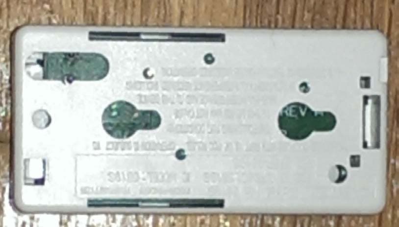
Click to zoom
Application Details
- Equipment Class
- DSC - Part 15 Security/Remote Control Transmitter
- Date of Grant
- Sep 30, 2015
- Application Purpose
- Original Equipment
- Date of Application
- Sep 30, 2015
- Equipment Note
- Shock Processor Transmitter
- Frequency Range
- 344.94000000 - 344.94000000
- Company
- Ademco Inc.
- Country
- United States
Documents & Files
Document Text
Text extracted from the exhibit documents filed with the FCC. Open a document above to read the original.
Users Manual
5819S Wireless Shock Sensor and Transmitter – Installation Instructions The 5819S includes an omni-directional, built-in shock sensor, and is designed to protect window and door surroundings. Use this Shock Sensor and Transmitter with alarm systems that support Honeywell 5800 Series wireless devices. Typical shock protection area: 6 - 8 feet / 3 - 4 foot radius (1.8m – 2.44m / 0.91m – 1.23m radius); The coverage area can vary depending on the mounting surface. The device supports three unique zones or “loops”: Loop 1: Normally Open, built-in shock sensor* Loop 2: Normally closed, built in reed switch, used with the included magnet Loop 3: Externally wired, closed-circuit contact loop connected to the Terminal Block *Note: This device features the option to enable Loop 1 to report both shock and reed switch faults to the panel on a single zone (see Enroll and Program section for details). Open the Sensor Install the Battery BATTERY CAUTION: Risk of fire, explosion, and burns. Do not recharge, disassemble, heat above 212°F (100°C), or incinerate. Dispose of used batteries properly. Keep away from children. Enroll and Program 1. Install the battery and ensure all the DIP Switches are OFF (Highest Sensitivity setting). 2. Assign an individual zone number to each loop used* and assign the zones as Input Type = 3 (Supervised RF). *Note: To set Loop 1 to report both shock and reed switch faults on a single zone, enroll Loop 1 (do not enroll Loop 2), and set DIP Switch 4 ON after enrollment. 3. Activate any of the device loops (see loop descriptions above) to transmit the device serial number to the control. • For Loop 1, trigger the shock sensor by shaking the device, or create a shock near the mounted device. • For Loop 2, move the magnet close to and away from the reed switch to trigger it. • For Loop 3, Open and close the contact according to its instructions. 4. Trigger again to complete enrollment. The LED will flash rapidly to indicate the device is transmitting to the control. Alternatively, enter the device serial number manually when prompted for the information. DIP Switch Settings After enrollment, test and adjust the device sensitivity until the desired setting is achieved. (Refer to the Test section.) DIP SWITCH SETTING Most Sensitive (use this setting for enrollment) High Sensitivity Medium Sensitivity Low Sensitivity *Set ON - Loop 1 reports both shock and reed switch faults on a single zone Set OFF – Loop 1 reports shock only Do NOT Remove the PC Board from the back case PRELIMINARY DRAFT II’s – 06/09/15 Mount the Sensor After enrolling and before mounting permanently, conduct Go/No Go tests (see the control's instructions) to verify adequate signal strength. Reorient or relocate the device if necessary. The device can be mounted in any direction for shock sensing. If using the magnet, install it within 1/2” (12.7mm) of the device as shown. Test Use a hard tool to carefully simulate shock impacts on or near the area where the device is mounted. The LED lights each time the shock vibrations trip the device. Adjust the device sensitivity as needed for the application. Specifications Power: 1 x 3 V , Lithium Battery (included); Panasonic CR123A, Duracell DL123 or DL123A, Honeywell 466 Operating Temperature: 14° to 131° F / -10° to 55° C (Agency Compliance 32° to 120° F / 0° to 49° C) Relative Humidity: Up to 95% (Agency Compliance up to 93%); non-condensing Dimensions: 3.05” H x 1.54” W x 1” D (77.47mm H x 39.12mm W x 25.4mm D) Product must be tested at least once each year. Approval Listings FCC part 15, Class B verified IC, RSS-210, Class B verified ETL FEDERAL COMMUNICATIONS COMMISSION & INDUSTRY CANADA STATEMENTS The user shall not make any changes or modifications to the equipment unless authorized by the Installation Instructions or User's Manual. Unauthorized changes or modifications could void the user's authority to operate the equipment. CLASS B DIGITAL DEVICE STATEMENT This equipment has been tested to FCC requirements and has been found acceptable for use. The FCC requires the following statement for your information: This equipment generates and uses radio frequency energy and if not installed and used properly, that is, in strict accordance with the manufacturer's instructions, may cause interference to radio and television reception. It has been type tested and found to comply with the limits for a Class B computing device in accordance with the specifications in Part 15 of FCC Rules, which are designed to provide reasonable protection against such interference in a residential installation. However, there is no guarantee that interference will not occur in a particular installation. If this equipment does cause interference to radio or television reception, which can be determined by turning the equipment off and on, the user is encouraged to try to correct the interference by one or more of the following measures: • If using an indoor antenna, have a quality outdoor antenna installed. • Reorient the receiving antenna until interference is reduced or eliminated. • Move the radio or television receiver away from the receiver/control. • Move the antenna leads away from any wire runs to the receiver/control. • Plug the receiver/control into a different outlet so that it and the radio or television receiver are on different branch circuits. • Consult the dealer or an experienced radio/TV technician for help. INDUSTRY CANADA CLASS B STATEMENT This Class B digital apparatus complies with Canadian ICES-003. Cet appareil numérique de la classe B est conforme à la norme NMB-003 du Canada. FCC / IC STATEMENT This device complies with Part 15 of the FCC Rules, and RSS-210 of Industry Canada. Operation is subject to the following two conditions: (1) This device may not cause harmful interference, and (2) This device must accept any interference received, including interference that may cause undesired operation. Cet appareil est conforme à la partie 15 des règles de la FCC & de…
Text truncated - open the document above for the full version.
External Photos
EXHIBIT 4-1 CFS8DL5819S / 573F-5819S Page 1 of 1 EXTERNAL PHOTOS - 5819S These are the external photos for the manufacturer product variant '5816S', which excludes the populated terminal block. CASE EXTERIOR CASE FRONT CASE BACK
ID Label/Location Info
EXHIBIT 8 CFS8DL5819S / 573F-5819S Page 1 of 2 FCC / IC LABEL INFORMATION Because the White-on-White lettering that is molded indo the back plastic does not photograph well, we are supplying an ENGINEER'S DRAWING of the back (bottom) plastic. ENGINEER'S DRAWING OF THE MOLDED FCC / IC LABEL ON THE BACK PLASTIC
Internal Photos
EXHIBIT 4-2 CFS8DL5819S / 573F-5819S Page 1 of 1 INTERNAL PHOTOS - 5819S PCB IN PLASTIC TOP OF PCB BOTTOM OF PCB
Test Report
NVLAP Lab code: 200246-0 FCC CFR47 PART 15 SUBPART C MANUFACTURER’S TEST REPORT FOR WIRELESS SHOCK PROCESSOR AND TRANSMITTER MODEL NUMBER: 5819S FCC ID: CFS8DL5819S REPORT NUMBER: R10784367-E1A ISSUE DATE: 2015-09-11 Prepared for HONEYWELL SECURITY 2 CORPORATE CENTER DR SUITE 100 PO BOX 9040 MELVILLE NY, 11747, USA Prepared by UL LLC 12 LABORATORY DR. RESEARCH TRIANGLE PARK, NC 27709 USA TEL: (919) 549-1400 REPORT NO: R10784367-E1A DATE: 2015-09-11 FCC ID: CFS8DL5819S Page 2 of 18 UL LLC FORM NO: 03-EM-F00858 12 Laboratory Dr., RTP, NC 27709 TEL: (919) 549-1400 This report shall not be reproduced except in full, without the written approval of UL LLC. Revision History Ver. Issue Date Revisions Revised By 1 2015-06-23 Initial Issue Jeff Moser 2 2015-09-11 Revised antenna type (page 7), 15.231e limits to 15.231b limits (Section 7.1) and Test Procedure info (page 14). Jeff Moser REPORT NO: R10784367-E1A DATE: 2015-09-11 FCC ID: CFS8DL5819S Page 3 of 18 UL LLC FORM NO: 03-EM-F00858 12 Laboratory Dr., RTP, NC 27709 TEL: (919) 549-1400 This report shall not be reproduced except in full, without the written approval of UL LLC. TABLE OF CONTENTS 1. ATTESTATION OF TEST RESULTS ..................................................................................4 2. TEST METHODOLOGY ......................................................................................................5 3. FACILITIES AND ACCREDITATION ..................................................................................5 4. CALIBRATION AND UNCERTAINTY .................................................................................5 4.1. MEASURING INSTRUMENT CALIBRATION ...............................................................5 4.2. SAMPLE CALCULATION .............................................................................................5 4.3. MEASUREMENT UNCERTAINTY ................................................................................6 5. EQUIPMENT UNDER TEST ................................................................................................7 5.1. DESCRIPTION OF EUT ...............................................................................................7 5.2. DESCRIPTION OF AVAILABLE ANTENNAS ...............................................................7 5.3. SOFTWARE AND FIRMWARE .....................................................................................7 5.4. WORST-CASE CONFIGURATION AND MODE ...........................................................7 5.5. MODIFICATIONS .........................................................................................................7 5.6. DESCRIPTION OF TEST SETUP .................................................................................8 6. TEST AND MEASUREMENT EQUIPMENT ........................................................................9 6.1. DUTY CYCLE .............................................................................................................10 7. RADIATED EMISSION TEST RESULTS...........................................................................11 7.1. TX RADIATED SPURIOUS EMISSION ......................................................................11 REPORT NO: R10784367-E1A DATE: 2015-09-11 FCC ID: CFS8DL5819S Page 4 of 18 UL LLC FORM NO: 03-EM-F00858 12 Laboratory Dr., RTP, NC 27709 TEL: (919) 549-1400 This report shall not be reproduced except in full, without the written approval of UL LLC. 1. ATTESTATION OF TEST RESULTS COMPANY NAME: HONEYWELL SECURITY 2 CORPORATE CENTER DR SUITE 100 PO BOX 9040 MELVILLE, NY, 11747, USA EUT DESCRIPTION: WIRELESS SHOCK PROCESSOR AND TRANSMITTER MODEL: 5819S SERIAL NUMBER: Non-serialized sample (Sample #1) DATE TESTED: June 03-04, 2015 APPLICABLE STANDARDS STANDARD TEST RESULTS FCC PART 15 SUBPART C (Duty Cycle, Fundamental and Spurious Emissions, only). PASS UL LLC tested the above equipment in accordance with the requirements set forth in the above standards. All indications of Pass/Fail in this report are opinions expressed by UL LLC based on interpretations and/or observations of test results. Measurement Uncertainties were not taken into account and are published for informational purposes only. The test results show that the equipment tested is capable of demonstrating compliance with the requirements as documented in this report. Note: The results documented in this report apply only to the tested sample, under the conditions and modes of operation as described herein. This document may not be altered or revised in any way unless done so by UL LLC and all revisions are duly noted in the revisions section. Any alteration of this document not carried out by UL LLC will constitute fraud and shall nullify the document. This report must not be used by the client to claim product certification, approval, or endorsement by NVLAP, NIST, any agency of the Federal Government, or any agency of any government. Approved & Released For UL LLC By: Prepared By: Bob DeLisi Jeff Moser Certification Engineer EMC Program Manager UL – Consumer Technology Division UL – Consumer Technology Division REPORT NO: R10784367-E1A DATE: 2015-09-11 FCC ID: CFS8DL5819S Page 5 of 18 UL LLC FORM NO: 03-EM-F00858 12 Laboratory Dr., RTP, NC 27709 TEL: (919) 549-1400 This report shall not be reproduced except in full, without the written approval of UL LLC. 2. TEST METHODOLOGY The tests documented in this report were performed in accordance with ANSI C63.10-2009, FCC CFR 47 Part 2 and FCC CFR 47 Part 15. This report is a manufacturer’s specification report that included duty cycle, fundamental and radiated spurious, only. Note – Radiated testing above 1GHz was performed on a 1.5m table height, per ANSI C63.10: 2013. All other testing was performed per ANSI C63.10: 2009. 3. FACILITIES AND ACCREDITATION The test sites and measurement facilities used to collect data are located at 12 Laboratory Dr., Research Triangle Park, NC 27709, USA. 12 Laboratory Dr., RTP, NC 27709 Chamber A…
Text truncated - open the document above for the full version.
Test Report
EXHIBIT 6 CFS8DL5819S / 573F-5819S Page 1 of 2 TEST EQUIPMENT USED Part 15.231, ANSI C63.4, RSS 210 This is a list of test equipment used for Occupied Bandwidth (Exhibit 5-4). Additional test equipment used can be found in the radiated emissions lab reports: exhibits 5-3A & 5-3B. Note: Calibration Certificates are on following pages. Test Equipment list for Honeywell OBW Measurements EQUIPMENT: MANUFACTURER: MODEL: CAL DATE: CAL DUE DATE: Spectrum Analyzer Rohde & Schwarz FSU3 5/7/2014 5/7/2015 If you need any additional information from Honeywell, please contact: Andrew Roussin, Engineer (Acting for Mark Schmidt) Phone (Direct): 516-577-5935 Email: [email protected] ili ]xi ul:.it!lli =r:i ,,,.l : iiiri[i\i Issue Date: Dsrir,+**;_d ill$liiliffi}i]lllllilii ili{gil GENERAL CALIBRATION. INC. 2 MARS COURT BOONTON. NJ O7OO5 ffiffi' General Calibration, Inc. uu:tn* :t::i:::::: t:::::::::::t: :: .: :iut:u: ::iuu::u +t:tit!:RRtax : , 4:r, 1ks*l,r..::: ..:i:ii;r{:/: }d#,' ;l,:1 ,- , .i.f , ",a' ' r{m'fr,,':- ., 1 15m l;FE+ ;,*++;r.r ,, Certificate #: GC48-11390 Work Order #z 48GCl47 Customer #z 001464 _MET$:O PASSED 0510712015 _ 0666rs R&S spECtnuvr nNap;zen n.o c:"/ tyyy.eio;3 __ - 12 MONTHS 05t07t20t4 2 Mars Court, Boonton, New Jersey 07005 Phone (973)299-2950 Fax (973) 299-0595 Ass 9t T-18 N-o-::"-* . Modg_lltumb-el: -s--91-ia-!=-\l.upb_."1___" fg_s_q9cre$"Byi Job Title: C,llibratjog Res-yJ!; C-_al, Dpg* D-ate-: -.'. Owner's Email: iffiltlrll,lfli'iiiii;a**i *;T.il#$$glgfii;t.$;;# np*ff=!,,$ xl,ill*w1i1 ,,,,,1,*6i,,'^iiiiiF,iiffiir',,,rlit HONEYWELL SECURTTY (001464) 2 CORPORATE CENTER DRTVE MELVILLE, NY 11747 fiffiffiffi 11493 --tFJj-: _-r9.9"92?* JTR "LryHHHHH,:Wi iiiffi #1iliiii il Calibration Notes: GENT,RA ! cA LIB l-AJ_l"qN - J 0 3 1 _ s yNrHE S IZ pD l_yppl ER t 2- 6 G_rrz GENERAL CALIBRATION 1I53 POWER METER 1204NZ:82s2 _ 10:040218J Jr2:u?0810 ?re:96?:80 . _ _?1?6a0f 88 us"3_?er134 51051 in* GENPRAL cAlrB-RA_rlgj __ 4t0 4 GENE$*I: CALJB YTI{\ 424 GENE**I 9*!IBS+TI9**N* J8: GENERA-L__cALrBl+rrgry f4e GENERALCALIBRATION 688 ATJ_E_I-U*r9"R ry_lalrENgY coy*\TP lollPR sENSol _ POWER SPLTTJER LEVEL GENERATOR 07 t29/20r4 ol:rz!lzor! 06/2U20.4 o'j!!!_slz"or+ 0612612014 0!lzPUtt 08/09t20r41640A01730 '[dsistoccni&6!tc6qil&[email protected]|ibntidsystdisincdaliecewithIso/IEcl?025.2005'ANsINcsLz540.t,ANsINcsLz51t0.3'ddIso 90ol2008'Thetestlinitsstat.dinthere?ottoorrcsPoddtodEMashcfdscalibtdiotedPublisIrdsPccifcsticofth.€quipmnt,rtth.points&st.<L obtgi!€[email protected]@M'[email protected]'fctttEpcrbf'a!"oofoquip&dafr6€cdibrdion(vcrmcadol)o'€qdt' Calibtdio! ofstandf&; rfrr. sisrdlrds ard iEt@diatc stsld$ds it ihi! cslibrario h!r b€.n chcck d dd crlibrEt d aFict the .bovo working strd rEasurfEnt d$ugh Natiooal lBtihn of Stmdnds ald T.chnolos/ or ott6 Natiotd M.$wnt Institutcs u!d.! CIPM MRA. Aty @dit d cslibdio ud.r d€nol.dwithA2lAaccredit€ds}rnbolond€cdihfttionc€'tifcate,IfifeAccr€ditedceiifcateiflud.sstlyuA4Edit.dit.mcdibntc4lh.ysJccl€&ly Best Unc.rcrinti.s rEpftsetrt e4and.d unc€$atui$ e4res$d d approximaoely lh€ 95% confdcncc l.wl uirg s covcragc bctor olk=2. 'Ite resnts do.unartcd i! this cedificste relat! oaly to dh€ iteo(s) oalitrried or testod Approved By .t{i)..-:),,.-u+' -.e:,i ;&:**1:':',*.* * General Calibration, Inc. - Q. A. Manager
Test Report
EXHIBIT 5-4 CFS8DL5819S / 573F-5819S Page 1 of 1 SHORT RANGE RADIO (SRR) OCCUPIED BANDWIDTH Test Conducted on 4/29/2015 Worst Case OBW ANSI C63.10 was used to measure the OBW for the '5816S' and the larger OBW (measured on the latter) is reported. RBW = 30KHz VBW = 100KHz OBW = 112.179KHz Occupied Bandwidth Limit @ 345 MHz (CFR47 §15.231(c) / RSS-210A1.1.3) 862.50 KHz
Test Setup Photos
EXHIBIT 5-2 CFS8DL5819S/ 573F-5819S PICTURES OF THE UNIT UNDER TEST & Test Setup Page 1 of 7 Section 2.1093(c) Photo of the test setup shall be provided. ANT1 Radiated Testing Below 1GHz - Front View Page 2 of 7 EXHIBIT 5-2 CFS8DL5819S/ 573F-5819S PICTURES OF THE UNIT UNDER TEST & THE TEST SETUP CONT. Radiated Testing Below 1GHz - Back View Page 3 of 7 EXHIBIT 5-2 CFS8DL5819S/ 573F-5819S PICTURES OF THE UNIT UNDER TEST & THE TEST SETUP CONT. Radiated RF Measurement Setup Above 1GHz - Front View Page 4 of 7 EXHIBIT 5-2 CFS8DL5819S/ 573F-5819S PICTURES OF THE UNIT UNDER TEST & THE TEST SETUP CONT. Radiated Testing Above 1GHz - Back View Page 5 of 7 EXHIBIT 5-2 CFS8DL5819S/ 573F-5819S PICTURES OF THE UNIT UNDER TEST & THE TEST SETUP CONT. XYZ Orientation Setup - X Axis Page 6 of 7 EXHIBIT 5-2 CFS8DL5819S/ 573F-5819S PICTURES OF THE UNIT UNDER TEST & THE TEST SETUP CONT. XYZ Orientation Setup - Y Axis Page 7 of 7 EXHIBIT 5-2 CFS8DL5819S/ 573F-5819S PICTURES OF THE UNIT UNDER TEST & THE TEST SETUP CONT. XYZ Orientation Setup - Z Axis
Contact Information
Applicant
Christian Fouth(Sr. Wireless Certification Engineer)
Test Firm
UL LLCRick Titus
Technical Specifications
| # | Rule Parts | Frequency Range | Power Output |
|---|---|---|---|
| 1 | 15.231 | 344.94 MHz - 344.94 MHz | - |
Other Applications from Ademco Inc.

CFS8DL5800MINIV
Jan 28, 2026Wireless Alarm Transmitter
Equipment Class
DXX - Part 15 Low Power Communication Device Transmitter
CFS8DLWTS800
Jan 12, 2026Wireless Alarm Transmitter
Equipment Class
DTS - Digital Transmission SystemCFS8DLCAMWEWI1
Jul 25, 2024VX5 HD Indoor Camera
Equipment Class
DTS - Digital Transmission System
CFS8DLCAMWEWO1
Sep 17, 2023VX3 HD Outdoor Camera
Equipment Class
NII - Unlicensed National Information Infrastructure TX
CFS8DLLMD500A
Jul 20, 2023Wireless door/window contact
Equipment Class
DTS - Digital Transmission System