CFS8DL582Wireless Key Transmitter
Ademco Inc.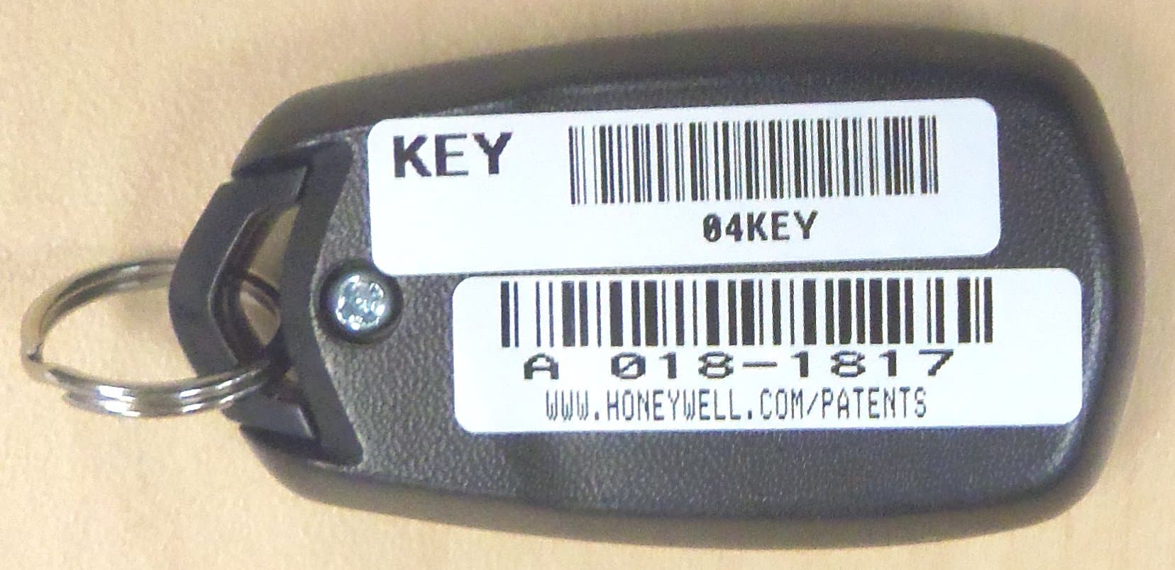
Click to zoom
Application Details
- Equipment Class
- DSC - Part 15 Security/Remote Control Transmitter
- Date of Grant
- Nov 11, 2015
- Application Purpose
- Original Equipment
- Date of Application
- Nov 11, 2015
- Equipment Note
- Wireless Key Transmitter
- Frequency Range
- 344.94000000 - 344.94000000
- Company
- Ademco Inc.
- Country
- United States
Documents & Files
Document Text
Text extracted from the exhibit documents filed with the FCC. Open a document above to read the original.
Users Manual
5834 58345834 5834- -- -4 44 4 Series SeriesSeries Series Wireless Key Transmitter Wireless Key TransmitterWireless Key Transmitter Wireless Key Transmitter INSTALLATION AND SETUP GUIDE GENERAL INFORMATION The 5834-4/5834-4EN key transmitters are portable wireless transmitters for use only with wireless alarm systems that support 5800 Series receivers (ex. VISTA series, L YNX PLUS, LYNX Touch). The 5834-4EN is identical to the 5834-4 except the 5834-4EN has a plated bezel and key ring. References to the 5834-4 throughout this document refer to both models. •Buttons are typically used for arming and disarming, but can be programmed for any appropriate zone response. •A button must be pressed and held until the LED begins to flash to activate a button function. This press and hold feature minimizes the possibility of accidental transmissions. (Refer to the Loop Number diagram at right). •The factory-installed replaceable lithium battery provides power for up to five (5) years. PROGRAMMING •Th e 5834-4 transmitter provides up to eight (8) functions and has an Optional high security (encrypted) mode that sends rolling-code encrypted messaging to the RF receiver. High Security Mode Note: This product is set to high security (encrypted) mode by the factory, and must be used with a receiver or control that supports high security mode. i.e., 5881EN, 5883, 6150RF, or 6160RF receiver or LYNXR Series control panel (Rev 13.1 or higher). For complete details on how to program the transmitter at the control panel, see the control unit's Installation Instructions. When programming, note the following: •Each 5834-4 transmitter has two unique serial numbers assigned during manufacture. •Each button on the unit also has a distinct "loop" number (refer to the Loop Number diagram at right) that you must program into the control panel during installation. •Assign each button to an individual zone and designate the Input Type as "BR" (Button Type). •When prompted for the serial number, press and release the appropriate button(s) twice, or, manually enter the serial number at the keypad. NOTE: Serial #2 is one (1) digit higher than serial #1, and is printed on the rear of the transmitter. CHANGING HIGH SECURITY / STANDARD MODE IN COMPATIBLE RECEIVERS A ND LOCALLY IN AN RF KEYPAD (eg., 6150RF) If used with LYNXR Series controls earlier than Revision 13.1, Standard Mode must be selected. The key fob is defaulted to high security mode. To change the mode do the following: 1.Select desired mode: Mode Simultaneously hold down for 5 secs... High-Security A - C - D (LED flashes Red when transmitting) Standard B - C - D (LED flashes Green when transmitting) Press any button to check the LED color. 2. When High Security mode is selected: •High Security mode MUST be activated in the control panel, see table below. •If the key fob is enrolled into the panel, put the security system into Go/No Go Mode then press the appropriate buttons as follows: Serial Number Simultaneously hold down until beeps sound... 1 A - B - C buttons (system beeps twice to confirm) 2 A - B - D buttons (system beeps twice to confirm) Note: Repeat for second serial number, if used. •If the key fob is enrolled locally into a 6150RF, go to Step 3 of 6150RF “Programming WITH Local Wireless Keys”. Loop Numbers for the 5834-4 Buttons 5834-008-V2 SERIAL #1 LOOP 4 SERIAL #1 LOOP 1 SERIAL #2 LOOP 1 SERIAL #2 LOOP 3 BUTT ON 4BUTTON 3 BUTTON 2BUTTON 1 SERIAL #1 LOOP 3 SERIAL #2 LOOP 4 SERIAL #1 LOOP 2 SERIAL #1 FUNCTIONS ACTIVATE WHEN THE RESPECTIVE BUTTON IS HELD DOWN UNTIL THE LED FLASHES. SERIAL #2 FUNCTIONS ACTIVATE WHEN THE TWO RESPECTIVE SERIAL #2 BUTTONS ARE PRESSED AT THE SAME TIME AND HELD DOWN UNTIL THE LED FLASHES. NOTE 1. 2. SERIAL #2 LOOP 2 A C B D Using a Button: To activate a programmed function, press and hold the appropriate key(s) until the LED begins to flash (about ½ second). SIA INSTALLATIONS: Use only serial #2/loop 2 (C & D keys) for the panic function. Do not use serial #1/loop 1 (D) key. ASSIGNING A WIRELESS KEY TO A USER •On most control panels, if the wireless key is assigned to arm and disarm the system, you must assign it to a user in order for it to operate. This is accomplished through User Code programming at the control panel. See control panel’s Installation and Setup Guide for specific instructions; table below summarizes the procedures. •If programming arming and disarming functions on both serial numbers, each serial number must be assigned to a separate user. On Vista 32/40/50/50P/100 and up You must assign a user to the button in order for it to operate. To assign a user number to the Arm/Disarm button: 1. Enter [4-digit User Code] + [8] + [User No.] + [new User Code]. 2. Answer Yes or No to the “Open/Close Report ?” question. 3. Answer Yes to the “RF Button ?” question. 4. Enter the zone number assigned to the button. 5. Keypad display shows summary of user information. 6. Test all functions for proper operation. On Vista-20P/15P/10P/Vista-21iP and variants You must assign a user to the button in order for it to operate, and must enter a sequence of keystrokes as described below. NOTE: There is a two-second timeout for keystroke commands on Vista P series panels, therefore you must enter the keystrokes as quickly as possible. 1. Enter [4-digit Master Code] + [8] + [User Number] + [# 4] + [two digit zone number] assigned to the fob. 2. Test all functions for proper operation. EXHIBIT 7-1A INSTALLATION INSTRUCTIONS REPLACING THE BATTERY The LED will not flash during transmission if the battery is low. Replace the battery as follows. 1. Remove the screw from the case back, then remove the case back. 2. Insert the blade of a small screwdriver under the battery as shown. 3. Twist the screwdriver to release the battery. IMPORTANT: After removing the old battery, wait 1 minute before installing a new battery. 4. With the Positive (+) end of a new battery facing UP, insert the battery as shown, sliding it under the gold tab, t…
Text truncated - open the document above for the full version.
External Photos
EXHIBIT 4-1A EXTERNAL PHOTOS CFS8DL582 / 573F-582 BOTTOM PLASTIC TOP PLASTIC
ID Label/Location Info
EXHIBIT 8C CFS8DL582 / 573F-582 LABEL INFORMATION SECTION 2.1033 (c) and Part 15.21 SECTION 2.1033 (c) Label and label location - A photo showing the identification label clearly (you must be able to see the name and FCC ID number), and the location on the device. In lieu of a photo for this, you may submit an engineer’s drawing. Part 15.21 / SECTION 2.1033 (c Statement - for all intentional and unintentional radiators is also printed on the label. All devices shall bear the following statement in a conspicuous location on the device: “ This device complies with Part 15 of the FCC Rules and RSS 210 of Industry Canada. Operation is subject to the following two conditions: (1) this device may not cause harmful interference, and (2) this device must accept any interference received, including interference that may cause undesired operation. “ (a)(5) When the device is so small or for such use that it is not practicable to place the statement specified under paragraph (a) of this section on it, the information required by this paragraph shall be placed in a prominent location in the instruction manual or pamphlet supplied to the user or, alternatively, shall be placed on the container in which the device is marketed. However, the FCC identifier or the unique identifier, as appropriate, must be displayed on the device. PLEASE SEE THE USERS MANUAL ( EXHIBIT 7 ) FOR THE STATEMENT DRAWING: CASE BACK INTERIOR DRAWING: CASE FRONT INTERIOR FCC ID Silkscreened on PCB here IC Number Silkscreened on PCB here IC Model on permanent label here. IC MODEL: 582 FCC ID: CFS8DL582 I C : 573F- 582
Internal Photos
EXHIBIT 4-2A INTERNAL PHOTOS CFS8DL582 / 573F-582 PCB IN PLASTIC BOTTOM OF PCB TOP OF PCB
Test Report
NVLAP Lab code: 200246-0 FCC CFR47 PART 15 SUBPART C MANUFACTURER’S TEST REPORT FOR WIRELESS KEY TRANSMITTER MODEL NUMBER: 582 FCC ID: CFS8DL582 REPORT NUMBER: R10784314-E1A ISSUE DATE: 2015-10-28 Prepared for HONEYWELL SECURITY 2 CORPORATE CENTER DR SUITE 100 PO BOX 9040 MELVILLE NY, 11747, USA Prepared by UL LLC 12 LABORATORY DR. RESEARCH TRIANGLE PARK, NC 27709 USA TEL: (919) 549-1400 REPORT NO: R10784314-E1A DATE: 2015-10-28 FCC ID: CFS8DL582 Page 2 of 18 UL LLC FORM NO: 03-EM-F00858 12 Laboratory Dr., RTP, NC 27709 TEL: (919) 549-1400 This report shall not be reproduced except in full, without the written approval of UL LLC. Revision History Rev. Issue Date Revisions Revised By -- 2015-06-25 Initial Issue Jeff Moser 1 2015-08-20 For marketing purposes, revised the model name from 5834-4 to 582. Due to this change, the FCC ID was changed from CFS8DL58242 to CFS8DL582. There are no differences in the ‘5834-4’ unit and the ‘582’ unit other than the model change. Jeff Moser 2 2015-10-01 Revised the Duty Cycle from 10% to 14.3%. Jeff Moser 3 2015-10-28 Revised test dates on page 4 of 18. Jeff Moser REPORT NO: R10784314-E1A DATE: 2015-10-28 FCC ID: CFS8DL582 Page 3 of 18 UL LLC FORM NO: 03-EM-F00858 12 Laboratory Dr., RTP, NC 27709 TEL: (919) 549-1400 This report shall not be reproduced except in full, without the written approval of UL LLC. TABLE OF CONTENTS 1. ATTESTATION OF TEST RESULTS ..................................................................................4 2. TEST METHODOLOGY ......................................................................................................5 3. FACILITIES AND ACCREDITATION ..................................................................................5 4. CALIBRATION AND UNCERTAINTY .................................................................................5 4.1. MEASURING INSTRUMENT CALIBRATION ...............................................................5 4.2. SAMPLE CALCULATION .............................................................................................5 4.3. MEASUREMENT UNCERTAINTY ................................................................................6 5. EQUIPMENT UNDER TEST ................................................................................................7 5.1. DESCRIPTION OF EUT ...............................................................................................7 5.2. DESCRIPTION OF AVAILABLE ANTENNAS ...............................................................7 5.3. SOFTWARE AND FIRMWARE .....................................................................................7 5.4. WORST-CASE CONFIGURATION AND MODE ...........................................................7 5.5. MODIFICATIONS .........................................................................................................7 5.6. DESCRIPTION OF TEST SETUP .................................................................................8 6. TEST AND MEASUREMENT EQUIPMENT ........................................................................9 6.1. DUTY CYCLE .............................................................................................................10 7. RADIATED EMISSION TEST RESULTS...........................................................................11 7.1. TX RADIATED SPURIOUS EMISSION ......................................................................11 REPORT NO: R10784314-E1A DATE: 2015-10-28 FCC ID: CFS8DL582 Page 4 of 18 UL LLC FORM NO: 03-EM-F00858 12 Laboratory Dr., RTP, NC 27709 TEL: (919) 549-1400 This report shall not be reproduced except in full, without the written approval of UL LLC. 1. ATTESTATION OF TEST RESULTS COMPANY NAME: HONEYWELL SECURITY 2 CORPORATE CENTER DR SUITE 100 PO BOX 9040 MELVILLE, NY, 11747, USA EUT DESCRIPTION: WIRELESS KEY TRANSMITTER MODEL: 582 SERIAL NUMBER: Non-serialized sample (Sample #1) DATE TESTED: June 03-25, 2015 APPLICABLE STANDARDS STANDARD TEST RESULTS FCC PART 15 SUBPART C (Duty Cycle, Fundamental and Spurious Emissions, only). PASS UL LLC tested the above equipment in accordance with the requirements set forth in the above standards. All indications of Pass/Fail in this report are opinions expressed by UL LLC based on interpretations and/or observations of test results. Measurement Uncertainties were not taken into account and are published for informational purposes only. The test results show that the equipment tested is capable of demonstrating compliance with the requirements as documented in this report. Note: The results documented in this report apply only to the tested sample, under the conditions and modes of operation as described herein. This document may not be altered or revised in any way unless done so by UL LLC and all revisions are duly noted in the revisions section. Any alteration of this document not carried out by UL LLC will constitute fraud and shall nullify the document. This report must not be used by the client to claim product certification, approval, or endorsement by NVLAP, NIST, any agency of the Federal Government, or any agency of any government. Approved & Released For UL LLC By: Prepared By: Bob DeLisi Jeff Moser Certification Engineer EMC Program Manager UL – Consumer Technology Division UL – Consumer Technology Division REPORT NO: R10784314-E1A DATE: 2015-10-28 FCC ID: CFS8DL582 Page 5 of 18 UL LLC FORM NO: 03-EM-F00858 12 Laboratory Dr., RTP, NC 27709 TEL: (919) 549-1400 This report shall not be reproduced except in full, without the written approval of UL LLC. 2. TEST METHODOLOGY The tests documented in this report were performed in accordance with ANSI C63.10-2009, FCC CFR 47 Part 2 and FCC CFR 47 Part 15. This report is a manufacturer’s specification report that included duty cycle, fundamental and radiated spurious, only. Note – Radiated testing above 1GHz was performed on a 1.5m table height, per ANSI C63.10: 2013. All other testing was performed per ANSI C63.10: 2009. 3. FACI…
Text truncated - open the document above for the full version.
Test Report
EXHIBIT 5-4 CFS8DL582 / 573F-582 Page 1 of 1 SHORT RANGE RADIO (SRR) OCCUPIED BANDWIDTH CFR47 §15.231(c): Periodic operation in the band 40.66-40.70 MHz and above 70 MHz. The bandwidth of the emission shall be no wider than 0.25% of the center frequency for devices operating above 70 MHz and below 900 MHz. For devices operating above 900 MHz, the emission shall be no wider than 0.5% of the center frequency. Bandwidth is determined at the points 20 dB down from the modulated carrier. RSS-210A1.1.3 Bandwidth of Momentary Signals For the purpose of Section A1.1, the 99% bandwidth shall be no wider than 0.25% of the centre frequency for devices operating between 70 MHz and 900 MHz. For devices operating above 900 MHz, the emission shall be no wider than 0.5% of the centre frequency. OBW Measurement RBW = 30KHz VBW = 100KHz OBW = 182.692KHz Occupied Bandwidth Limit @ 344.94 MHz (CFR47 §15.231(c) / RSS-210A1.1.3) 862.35 KHz
Contact Information
Applicant
Christian Fouth(Sr. Wireless Certification Engineer)
Test Firm
UL LLCRick Titus
Technical Specifications
| # | Rule Parts | Frequency Range | Power Output |
|---|---|---|---|
| 1 | 15.231 | 344.94 MHz - 344.94 MHz | - |
Other Applications from Ademco Inc.

CFS8DL5800MINIV
Jan 28, 2026Wireless Alarm Transmitter
Equipment Class
DXX - Part 15 Low Power Communication Device Transmitter
CFS8DLWTS800
Jan 12, 2026Wireless Alarm Transmitter
Equipment Class
DTS - Digital Transmission SystemCFS8DLCAMWEWI1
Jul 25, 2024VX5 HD Indoor Camera
Equipment Class
DTS - Digital Transmission System
CFS8DLCAMWEWO1
Sep 17, 2023VX3 HD Outdoor Camera
Equipment Class
NII - Unlicensed National Information Infrastructure TX
CFS8DLLMD500A
Jul 20, 2023Wireless door/window contact
Equipment Class
DTS - Digital Transmission System