CFS8DL5828Security accessory
Ademco Inc.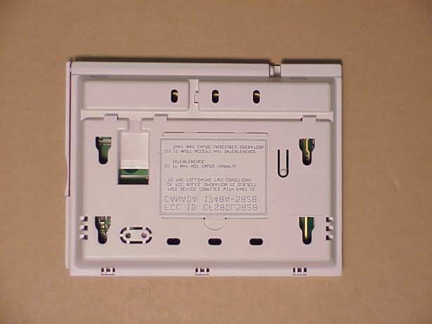
Click to zoom
Application Details
- Equipment Class
- DSR - Part 15 Remote Control/Security Device Transceiver
- Date of Grant
- Oct 02, 2002
- Application Purpose
- Original Equipment
- Date of Application
- Aug 29, 2002
- Equipment Note
- Security accessory
- Frequency Range
- 345.00000000 - 345.00000000
- Company
- Ademco Inc.
- Country
- United States
Documents & Files
Document Text
Text extracted from the exhibit documents filed with the FCC. Open a document above to read the original.
Users Manual
RADIO FREQUENCY EMISSIONS FCC ID: CFS8DL5828 Federal Communications Commission (FCC) Part 15 This device complies with part 15 of the FCC rules. Operation is subject to the following two conditions: (1) This device may not cause harmful interference, and (2) this device must accept any interference received, including interference that may cause undesired operation. Industry Canada CANADA: 1748A-5828 This Class B digital apparatus complies with Canadian ICES-003. Cet Appareil numérique de la classe B est conforme à la norme NMB-003 du Canada. FEDERAL COMMUNICATIONS COMMISSION (FCC) PART15 STATEMENT This equipment has been tested to FCC requirements and has been found acceptable for use. FCC requires the following statement for your information. This equipment generates and uses radio frequency energy and if not installed and used properly, that is, in strict accordance with the manufactures instructions, may cause interference with radio and television reception. It has been type tested and found to comply with the limits for a Class B computing device in accordance with specifications in Part 15 FCC Rules, which are designed to provide reasonable protection against such interference in a residential installation. However, there is no guarantee that interference will not occur in a particular installation. If this equipment causes interference to radio or television reception, which can be determined by turning the equipment off and on, the user is encouraged to try to correct the interference by one or more of the following measures: • If using an indoor antenna, have a quality outdoor antenna installed. • Reorient the receiving antenna until interference is reduced or eliminated. • Move the radio or television receiver away from a receiver/control. • Move the antenna leads away from any wire runs to the receiver/control. • Plug the receiver/control into a different outlet so that it and the radio or television receiver are on different branch circuits. If necessary, the user should consult the dealer or an experienced radio/television technician for additional suggestions. The user or installer may find the following booklet prepared by the Federal Communications Commission helpful: “Interference Handbook.” This booklet is available from the US Government Printing Office, Washington, D.C. 20402. The user shall not make any changes or modifications to the equipment unless authorized by the Installation Instructions or User’s Manual. Unauthorized changes or modifications could void the user’s authority to operate the equipment. ADEMCO Limited Warranty Alarm Device Manufacturing Company, a Division of Pittway Corporation, and its divisions, subsidiaries and affiliates ("Seller"), 165 Eileen Way, Syosset, New York 11791, warrants its products to be in conformance with its own plans and specifications and to be free from defects in materials and workmanship under normal use and service for 24 months from the date stamp control on the product or, for products not having an ADEMCO date stamp, for 12 months from date of original purchase unless the installation instructions or catalog sets forth a shorter period, in which case the shorter period shall apply. Seller's obligation shall be limited to repairing or replacing, at its option, free of charge for materials or labor, any product that is proved not in compliance with Seller's specifications or proves defective in materials or workmanship under normal use and service. Seller shall have no obligation under this Limited Warranty or otherwise if the product is altered or improperly repaired or serviced by anyone other than ADEMCO factory service. For warranty service, return product transportation prepaid, to ADEMCO Factory Service, 170 Michael Drive, Syosset, New York 11791. THERE ARE NO WARRANTIES, EXPRESS OR IMPLIED, OF MERCHANTABILITY, OR FITNESS FOR A PARTICULAR PURPOSE OR OTHERWISE, WHICH EXTEND BEYOND THE DESCRIPTION ON THE FACE HEREOF. IN NO CASE SHALL SELLER BE LIABLE TO ANYONE FOR ANY CONSEQUENTIAL OR INCIDENTAL DAMAGES FOR BREACH OF THIS OR ANY OTHER WARRANTY, EXPRESS OR IMPLIED, OR UPON ANY OTHER BASIS OF LIABILITY WHATSOEVER, EVEN IF THE LOSS OR DAMAGE IS CAUSED BY THE SELLER'S OWN NEGLIGENCE OR FAULT. Seller does not represent that the products it sells may not be compromised or circumvented; that the products will prevent any personal injury or property loss by burglary, robbery, fire or otherwise; or that the products will in all cases provide adequate warning or protection. Customer understands that a properly installed and maintained alarm may only reduce the risk of a burglary, robbery, fire or other events occurring without providing an alarm, but it is not insurance or a guarantee that such will not occur or that there will be no personal injury or property loss as a result. CONSEQUENTLY, SELLER SHALL HAVE NO LIABILITY FOR ANY PERSONAL INJURY, PROPERTY DAMAGE OR OTHER LOSS BASED ON A CLAIM THE PRODUCT FAILED TO GIVE WARNING. HOWEVER, IF SELLER IS HELD LIABLE, WHETHER DIRECTLY OR INDIRECTLY, FOR ANY LOSS OR DAMAGE ARISING UNDER THIS LIMITED WARRANTY OR OTHERWISE, REGARDLESS OF CAUSE OR ORIGIN, SELLER'S MAXIMUM LIABILITY SHALL NOT IN ANY CASE EXCEED THE PURCHASE PRICE OF THE PRODUCT, WHICH SHALL BE THE COMPLETE AND EXCLUSIVE REMEDY AGAINST SELLER. This warranty replaces any previous warranties and is the only warranty made by Seller on this product. No increase or alteration, written or verbal, of the obligations of this Limited Warranty is authorized. 165 Eileen Way, Syosset, New York 11791 Copyright 2001 PITTWAY CORPORATION ÊK0020fŠ K0020 8/02
Operational Description
CIRCUIT DESCRIPTION EXHIBIT 2-1 CFS8DL5828V The diversity antennas are selected via the antenna selector switch SW2, which is feeds TR Switch SW3 in order to select the receivers input or the transmitters output. SW2 and SW3 are under the control of microprocessor U1. The transmitter consists of U15, YL6, L6, L7, C50, C78, C79, etc. U15 is the phase-locked TX chip its FDE is YL6 ( 10.78125 Mhz X 32 = 345.0 Mhz ). Microprocessor U1 performs message encoding, and RX / TX switching. The receiver consists of U11, FL1, YL5, etc., and uses low side L.O. injection, it's FDE is YL4 ( 20.89375 Mhz X 16 = 334.3 Mhz ). The raw base-band data is processed by U13, U14, etc., before being sent to the microprocessor U1 for message decoding. U1 also encodes the keypad, and performs all control functions. U6 is a tone generator chip. U7 is the audio recorder / playback chip. U8 is the LCD display decoder chip.
Operational Description
FUNCTIONAL DESCRIPTION EXHIBIT 1-1 CFS8DL5828 The 5828V fixed transceiver is part of Ademco’s wireless 5800 alarm system. It is used in conjunction with portable transmitters (e.g. 5804) or portable transceivers (e.g. 5804BD). This allows remote control of the alarm system and provides remote indication that a control instruction has been enacted. These messages are transmitted at 345Mhz +/-82kHz using on-off keyed AM modulation. The 5828V does not send a regular supervision or check-in message, it transmits no other messages except those which are a confirmation of reception of manually initiated control messages which have been received from portable remote control transmitters and control and alarm messages.
Operational Description
DUTY CYCLE CALCULATION EXHIBIT 3-1 CFS8DL5828 Message protocol, timing, and duty cycle calculation. The data output is phase-encoded Manchester that has inherent 50% duty cycle and consists of 64 bits per word The 5828 is not supervised, and only sends user initiated messages. Each user initiated message, is just like the 5827BD (FCC ID: CFS8DL5828BD) has a nominal data rate of 3.7 kb/s (3.2kb/s min to 4.2kb/s max). Therefore the duty cycle is calculation is as follows: The word format consists of 64 bits, The duration of each bit is 312.5 uSec max. The duty cycle over a 100 mSec measuring period is calculated as follows: Duty cycle = Actual RF transmission ON time / 100 mSec Actual transmission ON time = 64 bits X 50% X 312.5 uSec = 10 mSec Therefore duty cycle = 10 / 100 mSec = .10 = 10%, and peak to average field strength is 20 db. The 5828 is also required to transmit a 'Site ID' message, just like the 5839US (FCC ID: CFS8DL5839US) Site ID messages consist of : A 16 bit preamble, ( 15 bits + one sync bit ) and 96 bits of control data. For a total of 112 bits of information. the total message is 25 mSec. long. The message is repeated five (5) times, every 120 mSec. (MIN) Therefore: the message is only sent once every 100 mSec. i.e.; 25 mSec. / 100 mSec. = .25 Further the Manchester has an inherent duty cycle of 50% making the total transmitter duty cycle: .25 X .50 = .125 X 100 = 12.5 % total transmitter on time.
Test Report
EXHIBIT 5-1 CFS8DL5828 Report of Measurements. Measurements were made at Ademco 's Measurement Facility at 160 Eileen Way , Syosset , NY 11791 , FCC Registration number : 90421. Measurements were made in accordance with the procedures and reporting requirements of ANSI C63.4-1992. The Test Set-Up (C63.4 section 10.1.3) is shown in the attached drawing. The sequence of testing (C63.4 section 10.1.7) for radiated emissions is as follows: A preliminary scan was conducted with the receiver antenna close to the EUT in order to identify the emission characteristics of the EUT (C63.4 section 8.3.1.1). The antenna and EUT were then placed at the proper separation with the EUT positioned on a non-conducting turntable. The EUT was rotated on the turntable to maximize the received signal strength, then the receiver antenna height was varied to further maximize the received reading. Thereafter, the device was again rotated to a peak output position and the antenna height was re-adjusted for maximum received signal. This procedure was re-iterated until there was no further increase in signal level. This procedure was performed with the EUT rotating in three orthogonal planes (C63.4 section 13.1.4.1) to generate a final maximum reading which is recorded on the radiated emissions result sheet. Similar measurements were made on the receiver to ensure compliance as an unintentional radiator. See Exhibit 6 for list of test equipment (C63.4 section 10.1.4). Note, Spectrum Analyzer resolution bandwidths set as follows; (Video Bandwidth set greater than RBW) - For occupied bandwidth measurements, RBW = 100kHz, (This is in accordance with the minimum RBW allowed by C63.4, which requires RBW greater than 5% of the FCC required occupied bandwidth spec of 0.25% of center frequency). - For radiated emissions below 1 GHz, the RBW = 100kHz. Detector function set to peak. - For radiated emissions above 1 GHz, the RBW = 1MHz. Detector function set to peak. OCCUPIED BANDWIDTH is shown on attached plot. RADIATED EMISSIONS are recorded on attached sheet.
Test Report
Frequency (MHz) Antenna Polarity ( V-H ) Meter Reading (dB uV) Cable/Amp Factor ( dB ) Antenna Factor (dB/M) Converted Reading ( uV/M ) Duty Cycle ( % ) Corrected Reading ( uV/M ) Limit @ 3 Meter ( uV/M ) 30 H 729 345 H 72.50 2.3 16.6637436.9 12.5 4,679.6 7,291 690 H 20.00 3.2 21.56 173.1 12.5 21.6 729 1035 H 18.0* 3.9 23.83193.2 12.5 24.1 500 1380 H 18.0* 4.6 24.91237.5 12.5 29.7 500 1725 V 18.0* 5.3 26.67315.1 12.5 39.4 729 2070 H 18.0* 6.3 28.47435.4 12.5 54.4 729 2415 H 18.0* 6.8 28.96487.6 12.5 61.0 729 2760 H 18.0* 7.0 29.75546.8 12.5 68.4 729 3105 H 18.0* 7.4 30.00627.6 12.5 78.4 729 3450 H 18.0* 12.0 29.951116.5 12.5 139.6 729 * NOTE:* = NOISEFLOOR 4000 H 729 AUGUST, 22, 2002 GREG BARBATO KEN ADDY DATE:____________________ TESTED BY:_________________________APPROVED BY:________________________ ADEMCO 5828 (TRANSMITTER) TEST SAMPLE (model): _______________________________________________________________________________ TEST METHOD: ANSI C63.4-1992 TEST SPECIFICATION: FCC PART 15, SUBPART C. NOTES: 1) Fo= 345 MHZ 2) DETECTOR = PEAK. 3) FREQUENCY RANGE SCANNED TO 4 GHz. (METER READING +CABLE /AMP FACTOR +ANTENNA FACTOR) 20 4) CONVERTED READING = 10 5) CORRECTED READING = CONVERTED READING X DUTY CYCLE 6) SIX HIGHEST EMISSIONS RECORDED. ALARM DEVICE MANUFACTURING COMPANY 165 EILEEN WAY CFS8DL5828 SYOSSET, NY 11791 FCC ID#____________________
Test Report
EXHIBIT 6 CFS8DL5828 Test Equipment list 1. Antenna: RGA-60 S/N: 3127 Cal. on: 11/01/01 Cal. due: 11/01/02 2. Antenna: Log Periodic S/N:447 Cal. on: 11/01/01 Cal. due: 11/01/02 3. Spectrum Analyzer H. P. 8563E S/N:3246A00232 Cal. on: 03/01/02 Cal. due: 03/01/03
Contact Information
Applicant
Christian Fouth(Sr. Wireless Certification Engineer)
Technical Contact
Alarm Device Manufacturing CompanyKen L Addy
[email protected]516-921-6704
A Division of Pittway Corporation · Syosset, New York · United States
Non-Technical Contact
Alarm Device Manufacturing CompanyKen L Addy
[email protected]516-921-6704
Test Firm
AdemcoKenneth Addy
Technical Specifications
| # | Rule Parts | Frequency Range | Power Output |
|---|---|---|---|
| 1 | 15C | 345 MHz - 345 MHz | - |
Other Applications from Ademco Inc.

CFS8DL5800MINIV
Jan 28, 2026Wireless Alarm Transmitter
Equipment Class
DXX - Part 15 Low Power Communication Device Transmitter
CFS8DLWTS800
Jan 12, 2026Wireless Alarm Transmitter
Equipment Class
DTS - Digital Transmission SystemCFS8DLCAMWEWI1
Jul 25, 2024VX5 HD Indoor Camera
Equipment Class
DTS - Digital Transmission System
CFS8DLCAMWEWO1
Sep 17, 2023VX3 HD Outdoor Camera
Equipment Class
NII - Unlicensed National Information Infrastructure TX
CFS8DLLMD500A
Jul 20, 2023Wireless door/window contact
Equipment Class
DTS - Digital Transmission System