CFS8DL5828VSecurity Transceiver
Ademco Inc.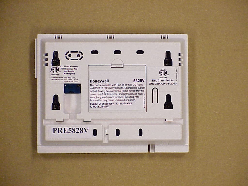
Click to zoom
Application Details
- Equipment Class
- DSR - Part 15 Remote Control/Security Device Transceiver
- Date of Grant
- May 18, 2010
- Application Purpose
- Original Equipment
- Date of Application
- May 17, 2010
- Equipment Note
- Security Transceiver
- Frequency Range
- 345.00000000 - 345.00000000
- Company
- Ademco Inc.
- Country
- United States
Documents & Files
Document Text
Text extracted from the exhibit documents filed with the FCC. Open a document above to read the original.
Users Manual
K0020V3 5/10 Rev. A ADEMCO 5828/5828V Wireless Bidirectional Fixed-Word Keypads INSTALLATION AND SETUP GUIDE GENERAL INFORMATION The ADEMCO 5828 and 5828V are wireless, bidirectional, fixed-word, keypads that may be used in conjunction with LYNX and VISTA series residential control panels. VISTA systems require use of either a 5883 Transceiver (micro P/N WAK5119-X, where X = 3 or higher), 6150RF Keypad/ Transceiver (PC board P/N SA6150RFAS-T3 or higher), or 6160RF Keypad/Transceiver. The 5828/5828V keypads are not compatible with commercial control panels that have three-digit zone numbers (e.g., VISTA128BP). Both keypads provide: • Four programmable special function keys • Wall-mount plate for easy removal of the keypad and battery replacement • Optional Desktop mount /AC adapter kit, ADEMCO P/N 5828DM) • Battery-powered with 3-AA batteries The 5828V keypad additionally provides: • Memo/Message center • Voice Response – system status, zone information, and alarms with zone information • Stored Message LED indication • Built-in microphone and speaker NOTES: • The 5828/5828V cannot be used as the primary system keypad, and may not be used to program or test any security system. All systems require a hardwired keypad (or Compass Downloader) to do so. Once programmed, the 5828/5828V can be used to initiate all common functions of a fixed English keypad. 1 OFF 4 MAX 7 INSTANT READY 2 AWAY 5 TEST 8 CODE 0 3 STAY 6 BYPASS 9 CHIME # ARMED READY 5828-00-001-V0 A B C D 5828 Keypad with Front Cover Removed 5828V-00-002-V0 1 OFF 4 MAX 7 INSTANT READY 2 AWAY 5 TEST 8 CODE 0 3 STAY 6 BYPASS 9 CHIME # MESSAGE MIC ARMED READY RECORD VOLUME PLAY STATUS FUNCTIONVOICE D C B A 5828V Keypad with Front Cover Removed Operation (See NOTE below) 1. Battery-Powered Operation: When powered by battery, the keypad activates when any key is pressed. When the [✱] key is pressed, the keypad sends a system status request, and displays and/or annunciates the present status transmitted by the system. 2. AC-Powered Operation: When powered by AC, the keypad remains active at all times. Any change in system status will cause the display to automatically turn on (if blank) and display/annunciate the new status. If AC power is lost, the keypad will revert to battery-powered operation until AC power is restored and a new status request is made ([✱] key). NOTE: Whether the unit is powered by battery or AC, the 5828/5828V may take up to 5 seconds to display and/or annunciate the new status after pressing the [✱] key. WALL MOUNTING Before mounting the 5828 & 5828V permanently, determine a good RF location as follows: • If interfacing to a LYNX panel, try communicating with the panel from different locations. • If interfacing to a VISTA panel, perform a Go/No Go test from the panel. Refer to the Go/No Go test mode in the Installation and Setup Guide for the panel. Avoid mounting locations on or near large metal objects, since these can decrease the transmission range or block transmissions. • Secure the mounting plate to the wall, using proper sized hardware through the six mounting holes. • Plug the cord from the optional power pack into the keypad’s DC input connector, and route the wires through the wire guides on the back of the keypad. • Position the keypad over the mounting plate and slide down, engaging the four retaining clips on the plate with the receptacles on the keypad. DESKTOP MOUNTING For full portability, the keypad may be placed in any conven- ient, RF-suitable location and operated in its battery- powered mode, or near an AC outlet to be powered by the optional Power Pack/Desktop Mounting Kit, ADEMCO P/N 5828DM. BATTERY INSTALLATION OR REPLACEMENT CAUTION: Remove the AC/DC power connector from the keypad (if applicable), before attempting to install or replace the batteries. 1. Separate the keypad from its mounting plate by sliding the keypad up and away from the mounting plate. 2. Open the battery compartment door to expose the batteries. - 2 - 3. Install or replace the 3-1.5 Volt AA batteries in the battery compartment. Always replace all three batteries at once to ensure normal operation of the keypad over the anticipated battery lifetime. Make sure that battery positive (+) and negative (–) terminals are properly oriented with the battery spring clip connections. Refer to battery placement graphic below. batt_case-001-V0 AA BATTERY AA BATTERY AA BATTERY Battery Compartment 4. Reattach the keypad to its mounting plate by aligning the four mounting holes in the keypad case back with the four mounting clips on the mounting plate. Lower the keypad onto the clips. PROGRAMMING The following two items must be programmed in the keypad by the installer. • House ID Code (Step 1 in Installer Programming mode)* • System Type (Step 2 in Installer Programming mode) *The same House ID Code must also be programmed in the control panel. Programming a different House ID will disable communication. Installer Programming Enter the program mode by pressing the [1] and [3] keys simultaneously for five (5) seconds. The display alternately flashes “00” and two dashes (--). NOTES: • Entering a value other than one specified in the following steps may cause unpredictable results. • This keypad exits programming mode 15 seconds after the last key is pressed. Pressing any key will extend the 15-second active time. If the unit times out before you have pressed the star (✱) key to save a programmed value, you will need to re-enter the Programming mode and reprogram the option. STEP ACTION DISPLAY 1. Press [1] (House ID Code) (10 = default) Enter the two-digit house code (01-31) Press [✱] to continue. Alternately flashes “t1” and the 2- digit house code. 2. Press [2] (System Type). Press (1) for VISTA Press (2) for LYNX (2 = default) Press [✱] to continue. Alternately flashes “t2” and (1 or 2) 3. Press [3] (Exit Delay) Press 0-9 in 15 second increments. Example: If you press 3, exit delay would be 3 times 15 seconds for a total of 45 secon…
Text truncated - open the document above for the full version.
External Photos
EXHIBIT 4-1 EXTERNAL PICTURES 5828V / 573F-5828V TOP PLASTIC BOTTOM PLASTIC:
ID Label/Location Info
EXHIBIT 8 LABEL INFORMATION CFS8DL5828V / 573F-5828V SECTION 2.1033 (c) and Part 15.21 SECTION 2.1033 (c) Label and label location - A photo showing the identification label clearly (you must be able to see the name and FCC ID number), and the location on the device. In lieu of a photo for this, you may submit a engineer’s drawing. Part 15.21 Statement - for all intentional and unintentional radiators is also printed on the label. All devices shall bear the following statement in a conspicuous location on the device: “ This device complies with Part 15 of the FCC Rules Operation is subject to the following two conditions: (1) this device may not cause harmful interference, and (2) this device must accept any interference received, including interference that may cause undesired operation. “ ENGINEERS DRAWING: EXACT PHYSICAL LOCATION ON THE UNIT:
Internal Photos
EXHIBIT 4-1 INTERNAL PICTURES CFS8DL5828V / 573F-5828V PCB IN PLASTIC: TOP PCB: BOTTOM PCB:
Test Report
EXHIBIT 5-1 CFS8DL5828V / 573F-5828V Report of Measurements . Measurements for the Intentional Radiator,and OBW were made in accordance with the procedures and reporting requirements at: Honeywell's OATS ( FCC No: 152762 & IC No:573F-1 ) which is located at: 2 Corporate Center Drive, Melville, NY 11747. Measurements were made in accordance with the procedure and reporting requirements of ANSI C63.4-2003. The Test Set-Up (C63.4 section 10.1.3) is shown in EXHIBIT 5-2; "Test Setup Photos". The sequence of testing (C63.4 section 10.1.7) for radiated emissions is as follows: A preliminary scan was conducted with the receiver antenna close to the EUT in order to identify the emission characteristics of the EUT (C63.4 section 8.3.1.1). The antenna and EUT were then placed at the proper separation ( 3 Meters) with the EUT positioned at 80 cm on a non-conducting turntable. The EUT was rotated on the turntable to maximize the received signal strength, then the receiver antenna height was varied between one (1) and four (4) Meters to further maximize the received reading. Thereafter, the device was again rotated to a peak output position and the antenna height wa s re-adjusted for maximum received signal. This procedure was re-iterated until there was no further increase in signal level. This procedure was performed with the EUT rotating in three orthogonal planes (C63.4 section 13.1.4.1) to generate a final maximum reading which is recorded on the radiated emissions result sheet. Similar measurements were made on the receiver to ensure compliance as an unintentional radiator. Note, The Spectrum Analyzer resolution bandwidths set as follows; (Video Bandwidth is always set 3X greater than RBW) For occupied bandwidth measurements, RBW = 30KHz and VBW = 100KHz. For radiated emissions below 1 GHz, the RBW = 100kHz. Detector function set to peak. For radiated emissions above 1 GHz, the RBW = 1MHz. Detector function set to peak. TRANSMITTER RADIATED EMISSIONS are recorded in "EXHIBIT 5-3". OCCUPIED BANDWIDTH is recorded in "EXHIBIT 5-4". RX RADIATED EMISSIONS are recorded in "EXHIBIT 5-5". LINE CONDUCTED EMISSIONS are recorded in "EXHIBIT 5-6". TEST EQUIPMENT ( per C63.4 section 10.1.4) is recorded in "EXHIBIT 6".
Test Report
EXHIBIT 5-4 OCCUPIED BANDWIDTH CFS8DL5828V / 573F-5828V MAXIMUM OCCUPIED BANDWIDTH = 862.35 KHz 5804E-1 OCCUPIED BANDWIDTH: 174.3 KHz
Test Report
EXHIBIT 5-5 CFS8DL5828V / 573F-5828V RX RADIATED EMISSIONS
Test Report
EXHIBIT 5-6 CFS8DL5828V / 573F-5828V LINE CONDUCTED EMISSIONS Honeywell Conducted Emissions - 150 kHz - 30 MHz Line 1 100.0K1.0M10.0M100.0M Frequency 0 10.0 20.0 30.0 40.0 50.0 60.0 70.0 80.0 90.0 100.0 Amplitude (dBμV) Product: 5828VE10:39:14 AM, Thursday, March 11, 2010 C:\Tile4\Honeywell profiles\GREGS STUFF\5828VE-cond.TIL Operator: GREG 5828VE Peak Quasi-peak Average QP Class B AVG Class B Honeywell Conducted Emissions - 150 kHz - 30 MHz Neutral (line 2) 100.0K1.0M10.0M100.0M Frequency 0 10.0 20.0 30.0 40.0 50.0 60.0 70.0 80.0 90.0 100.0 Amplitude (dBμV) Product: 5828VE10:39:14 AM, Thursday, March 11, 2010 C:\Tile4\Honeywell profiles\GREGS STUFF\5828VE-cond.TIL Operator: GREG 5828VE Peak Quasi-peak Average QP Class B AVG Class B Honeywell Security Measurements on highest points Table Quasi-Peak and Avg Operator: GREG Product: 5828VE C:\Tile4\Honeywell profiles\GREGS STUFF\5828VE-cond.TIL 10:39:14 AM, Thursday, March 11, 2010 Frequency CISPR B L1 QP margin L2 QP margin CISPR B L1 AVG margin L2 AVG margin MHz QP lim (dBμV) L1(±dB) (dBμV) L2(±dB) AVG lim (dBμV) L1(±dB) (dBμV) L2(±dB) 2.21164e+006 56.000 16.527 39.473 NAN NAN 46.000 8.100 37.900 NAN NAN 2.27763e+007 60.000 16.579 43.421 NAN NAN 50.000 8.211 41.789 NAN NAN 5828VE
Test Report
EXHIBIT 6 TEST EQUIPMENT USED CFS8DL6150RFT3 / 573F-6150RFT3 Section 15.231 and ANSI C63.4 This is a list of all test equipment used. Test Equipment list for Honeywell OATS: Equipment Mfg Model Cal Date Cal Due Spectrum Analyzer Rohde & Schwarz FSEA20 10/12/09 10/12/10 Antenna (‘Biconilog’) ETS (EMCO)Lindgren 3149 07/10/09 07/10/10 Transient Limiter HP 11947A 5/12/10 5/12/11 LISN EMCO 3825/2 10/16/09 10/16/10 PLEASE SE E PAGE 2- 6 FOR TEST EQUIPMENT TRACEABILITY If you need any additional information from Honeywell please contact: Greg Barbato RF Engineer (Acting for Ken Eskildsen) Phone (Direct): (516) 577-5863 Email: [email protected] I . : l:,irli r::::t::i.:,44i.,,i .: i:. illlil.,. lssue Date: 1011212009 Performed Bv: GENERAL CALIBRA-NON. INC. 2 MARS COURT MONTVILLE, NJ 07045 Equipmentlnformation ii '" ,:: Job No.: 018675 Manufacturer: R&S Description: SPECTRUM ANALYZER Deoartment: ALARMNET Temp./RH: 22 Ct45% Cal. Interval: 12 MONTHS CalDate:10t12t2009 Calibration Notes Company GENERALCALIBRATION 1031 GENERALCALIBRATION 434 GENERALCALIBRATION 650 GENERALCALIBRATION 774 GENERALCALIBRATION 967 General Calibration, Inc. 2 Mars Court, Boonton, New Jersey 07005 Phone (973) 299-2950 Fax (973) 299-0595 Asset Tag No.: MqdqlNumber: SerialNumber: Inspected By: Job Title: Calibration Result: Cal. Due Date: Certificate #: 15395MR Purchase Order: 5105648 Work Order #: MR309 Gustomer #: 001464 Location of Calibration: HONEYWELL SECURTTY (001464) 2 CORPOMTE CENTER DRIVE MELVILLE, NY 11747 10506 FSEA2O DE23427 MR::I METROLOGIST PASS 10t12t2010 Cal. Duo Date 02t02t2010 09t18t2010 12t08t2009 07 t13t2010 09t15t2010 Condition: Found In Tolerance and Lett In Tolerance Proceduro #GGP: R&S F$EA20 Standards Used To Calibrate Equipment | , ,,,' , ;,-',, r.D. SYNTHESIZED SWEEPER POWER SPLITTER POWER SPLITTER POWER SENSOR FUNCTION GENERATOR The above instrument has been checked and calibrated against the above working standard(s) which are traceable to the NIST. The test limits stated in the report correspond to the published specifications of the equipment, at the points tested. Afso, the collective uncertainties of measurement standards do not exceed 25o/o of lhe tolerance of the characteristics being caliprated, wlere possible. The metrology procedures utilized conform to and satisry the requirements set forth in ANSYNCSL 2540-1-1994,10 cFR part 21, lso 9001-2000, tso 10012-2003. and MtL-srD 4s662A. Approved By. General Calibration, Inc. - Q. A. Manaqer Page +of 1 This cedifcate is not a contrad. We are not responsible for any damages resulting from the use ofthese standards by the customel This cedificate shall not be reproduced, except in tull, without the witen notification ofceneral Calibralion: Inc. fssue Date:05/1212009 General Calibration, Inc. 2 Mars Court, Boonton, New Jersey 07005 Phone (973) 299-2950 Fax (973) 299-0595 Certificate #: 1€09MR Purchase Order: 5105648 Work Order #: MR267 Customer #: 00{4'84 GENEML CALIBMTION. INC. 2 MARS COURT BarCode: 096188 [4anukstu ref; *_hlP__*_ -o,pxnpti-o:t-"-..JRAN$EI-\I.LMIIEB -."._" .""-"*"" * HONEYWELL SECURTTY (1464) 2 CORPORATE CENTER DRIVE MELVILLE, NY 11747 Instrument l.D.: 10131 JilsdeLNumheL* **1J9*74 SerialNumber: 3107A02782 "-Qene,rtmsnL- Inspected By: MR1 MONTVILLE, NJ 07045 Jemp"lB,U- " ?2. *9*L H"- ls Job Title;- . *.."..".-...* -[dE]ROLQ.G|ST"* _. * Calibration Result: PASS Cal.lnterval: 12 MONTHS CalDate: 05t12t2049 Cal. Due Date: 5nznu0 Found In Tolerance and Left ln Tolerance GENFRAKEAUBBATI,9.N *. 5OE**SPESIBUMAIIAIYZF,R 9EN_E"RAI"_C.AHBR/$tON*-*93__8__*_S_|S1\|A"L**qE-NF"BAT_9B" __" *._". __*Q31-11/2010 08/2512009 The above instrument has been checked and calibrated against the above working standard(s) which are traceable to the NIST. The test limits stated in the-report correspond to the published specifications of the equipment, at the points tested. Also, the collective uncertainties of measurement standards do not exceed 25% of the tolerahce of the characteristics being 9?1i!Ft9_d.wlgre possible. The metrology procedures utilized conform to and satisry the requirements set forth in ANSyNCSLZS40-1-1994, 10 CFR part21, tSO 9001-2000, tso 10012-2003, and MtL-srD'45662A. Approved av &ed g w.- General Calibration, Inc. - Q. A. Manager This cerdficate as not a contnct. We are not respon6ible lor any damag* rsult g tom lhe 6e of th€se standards by the dstomet This ertificate shall not be reprcduced, exept in full, without the witten noljf€tion oI General Calibration; Inc. , :,,i lil"''"i,t'': .i':il "'=' f ssue Date:1011612009 Pgff.(lf .iiEvi....,.,.l :,rr,rlr,,-.,,,,.,,,,,.'l,'..,,.,,,,:,ll' GENEML CALIBRATION, INC. 2 MARS COURT MONTVILLE, NJ 07045 Equipment lnformation . ,,:, Job No.: 004345 Manufacturer: EMCO Description: LISN Department: BLDG. 163 Temp./RH: 22 C | 45 % Cal. Interval: 12 MONTHS CalDate: 1011612009 GENERALCALIBRATION 7OO General Calibration, Inc. 2 Mars Court, Boonton, New Jersey 07005 Phone (973)299-2950 Fax (973) 299-0595 Certificate #: 15434MR Purchase Order: 51056€ Work Order #: MR309 Customer #: 001464 -:i ::: ::.ai:::: . a::a::ar:.:, . r' .Gel;;t0trr;,8ffi 05t28t2010 01t16t2010 HONEYWELL SECURtry (001464) 2 CORPORATE CENTER DRIVE MELVILLE, NY 11747 Asset Tag No.: ModelNumber: SerialNumber: Inspected By: Job Title: Calibration Result: Cat, Due Dqte: DIGITAL MULTIMETER 04892 3825t2 1076 MR,1 METROLOGIST PASS 10t16/2010 l ;,1r1;ls , r.t' I ,,li tli , l The above instrument has been checked and calibrated against the above working standard(s) which are traceable to the NIST. The test limits stated in the report correspond to the published specifications of the equipment, at the points tested. Also, the collective uncertainties of measurement standards do not exceed 25% of the tolerance of the characteristics beino calibrated, where possible. The metrology procedures utilized conform to and satisfy the requirements set forth in ANSI/NCSL 2540-1-1994,10 CFR part 21, ISO 9001-2000, tSO 10012-2003, an…
Text truncated - open the document above for the full version.
Test Report
5.2 AC power line conducted emission test requirements C63.4-2003 NOTE: A RBW OF 9 KHz AND A VBW OF 30 KHz WERE USED. AC powerline conducted emission measurements may be made at a facility that meets the requirements of this clause. This may include a shielded (screened) room or a radiated emission test site. 5.2.1 Reference groundplane The reference groundplane for measuring ac powerline conducted emissions is to consist of a floor earthgrounded conducting surface, which may be the metal floor of a shielded test chamber. The reference groundplane is to be at least 2 m by 2 m in size, and shall extend at least 0.5 m beyond the vertical projection (footprint) of the EUT or EUT arrangement. If the EUT normally does not make electrical contact with a groundplane, the reference groundplane shall be covered by insulating materials up to 12 mm thick. 5.2.2 Vertical conducting plane For measurements of ac powerline conducted emissions on a tabletop device, a vertical conducting plane or screen of at least 2 m by 2 m in size, shall be, if required, located 40 cm to the rear of the EUT. The vertical conducting plane or screen shall be electrically connected to the reference groundplane at intervals not greater than 1 m along its entire length through low impedance connections, e.g., 3 cm-wide metal straps. The metal wall of a screen room will normally satisfy this requirement. A tabletop device may be measured for ac powerline conducted emissions without a vertical conducting plane while maintaining the 80 cm EUT elevation specified in 6.2.1. However, in case of a dispute, ac powerline conducted emission measurements made on a tabletop device with a vertical, conducting plane in place shall take precedence. A vertical, conducting plane is not required for ac powerline conducted emissions measurements on a floorstanding device. A vertical, conducting plane shall not be used for any radiated emission measurements. 5.2.3 LISN installation LISNs may be required for ac powerline conducted emission measurements and may be used for radiated emission measurements. For exceptions, see 5.6. 5.2.3.1 LISN connected to the reference groundplane Where use of a LISN is required (see Clause 7), it shall be placed on and electrically bonded to the top surface of, or immediately beneath, the reference groundplane and bonded to the groundplane. If LISNs are kept on the test site for radiated emission measurements, it is preferred that they be installed under the reference groundplane with the ac power receptacle flush with the reference groundplane. Otherwise, NSA requirements may not be able to be met. The impedance at the receptacle end of any cable connected to the EUT end of the LISN (as contrasted to the impedance at the LISN terminals given in Figure 1), with the measuring instrument port of the LISN terminated in 50 Ω, shall be within +30% and –20% of the nominal LISN impedance shown in Figure 1 over the frequency range of the network to be used. See 4.1.2. If the attenuation (insertion loss) between the EUT receptacle and the measuring instrument port on the LISN is more than 0.5 dB, (see Annex E as an example of a method of measurement) it shall be taken into account when calculating the EUT emission levels. The site reference groundplane is the ground reference for the LISN. Ambient noise may be present on the ac powerlines at some locations and at some frequencies within the frequency range of interest. If the levels are sufficient to cause interference with readings made using an LISN, filtering of the ac power may be required. The filter should be inserted between the ac power supply and the ac input connection to the LISN, preferably as close as possible to the LISN to reduce interference pickup by the leads between the filter and the LISN. Where an isolation transformer is used between the ac power supply and the LISN, care shall be taken to ensure that this transformer’s rating is large enough to not affect the peak current drawn by the EUT (this may require up to ten times the kilovolt-ampere rating of the EUT). If other than air core inductors are used in the LISN, they shall be in a linear permeability range at the peak currents drawn by the EUT.
Test Setup Photos
EXHIBIT 5-2 PHOTOS OF TEST SETUP CFS8DL5828V / 573F-5828V SECTION 2.1093 (c) SECTION 2.1093 (c) Photo of the test setup shall be provided. INTENTIONAL RADIATOR SENSE VERT , UUT HORZ SENSE VERT , UUT VERT SENSE VERT , UUT OBLQ SENSE HORZ , UUT HORZ SENSE HORZ , UUT VERT SENSE HORZ , UUT OBLQ AT HONEYWELL’S OATS MEASUREMENT FACILITY AT: 2 CORPORATE CENTER DRIVE MELVILLE, NY 11747 PICTURE OF CONDUCTED TEST SETUP WITH LISN
Contact Information
Applicant
Christian Fouth(Sr. Wireless Certification Engineer)
Technical Contact
Honeywell International, Inc.Kenneth Eskildsen
[email protected]516-577-5878
2 Corporate Center Drive · Melville · United States
Test Firm
Honeywell International Inc.Mark Schmidt
Technical Specifications
| # | Rule Parts | Frequency Range | Power Output |
|---|---|---|---|
| 1 | 15.231 | 345 MHz - 345 MHz | - |
Other Applications from Ademco Inc.

CFS8DL5800MINIV
Jan 28, 2026Wireless Alarm Transmitter
Equipment Class
DXX - Part 15 Low Power Communication Device Transmitter
CFS8DLWTS800
Jan 12, 2026Wireless Alarm Transmitter
Equipment Class
DTS - Digital Transmission SystemCFS8DLCAMWEWI1
Jul 25, 2024VX5 HD Indoor Camera
Equipment Class
DTS - Digital Transmission System
CFS8DLCAMWEWO1
Sep 17, 2023VX3 HD Outdoor Camera
Equipment Class
NII - Unlicensed National Information Infrastructure TX
CFS8DLLMD500A
Jul 20, 2023Wireless door/window contact
Equipment Class
DTS - Digital Transmission System