CFS8DL5828V1Wireless Security Keypad
Ademco Inc.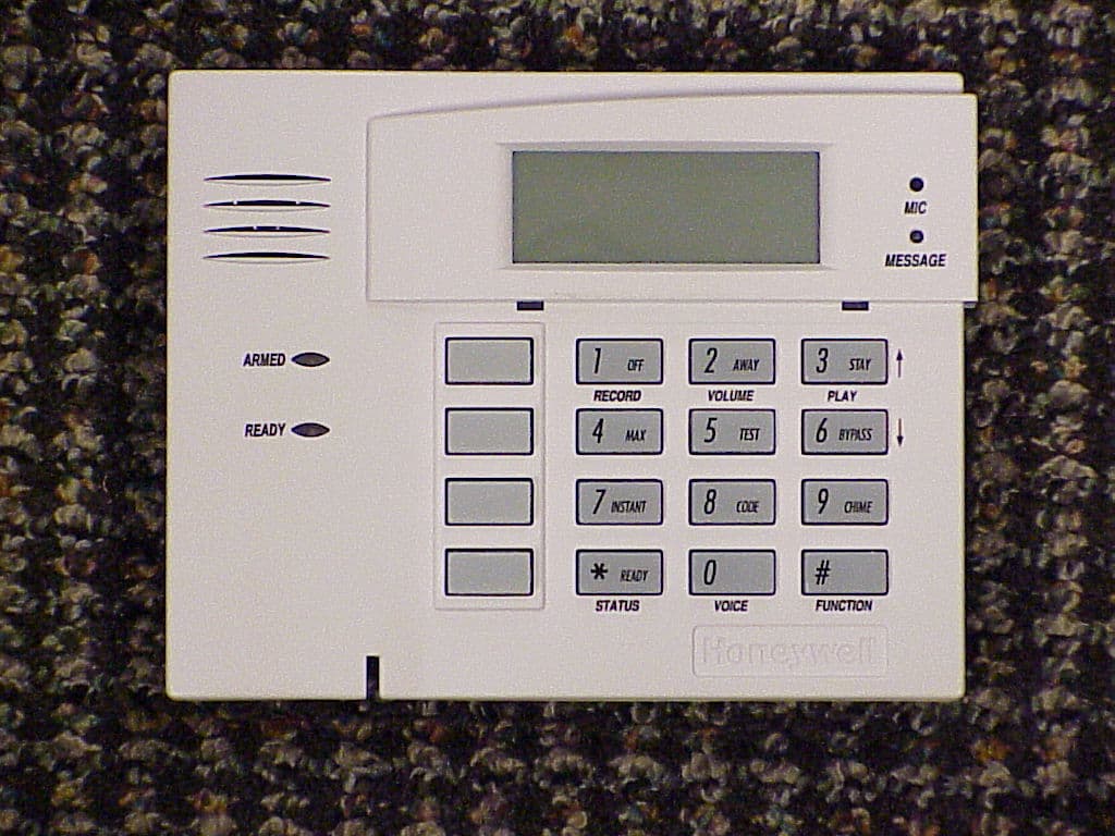
Click to zoom
Application Details
- Equipment Class
- DSR - Part 15 Remote Control/Security Device Transceiver
- Date of Grant
- Jul 21, 2011
- Application Purpose
- Original Equipment
- Date of Application
- Jul 08, 2011
- Equipment Note
- Wireless Security Keypad
- Frequency Range
- 344.94000000 - 344.94000000
- Company
- Ademco Inc.
- Country
- United States
Documents & Files
Document Text
Text extracted from the exhibit documents filed with the FCC. Open a document above to read the original.
Users Manual
K0020V4 7/11 Rev. A ADEMCO 5828/5828V Wireless Bidirectional Fixed-Word Keypads INSTALLATION AND SETUP GUIDE GENERAL INFORMATION The ADEMCO 5828 and 5828V are wireless, bidirectional, fixed-word, keypads that may be used in conjunction with LYNX and VISTA series residential control panels. VISTA systems require use of either a 5883 Transceiver (micro P/N WAK5119-X, where X = 3 or higher), 6150RF Keypad/ Transceiver (PC board P/N SA6150RFAS-T3 or higher), or 6160RF Keypad/Transceiver. The 5828/5828V keypads are not compatible with commercial control panels that have three-digit zone numbers (e.g., VISTA128BP). Both keypads provide: • Four programmable special function keys • Wall-mount plate for easy removal of the keypad and battery replacement • Optional Desktop mount /AC adapter kit, ADEMCO P/N 5828DM) • Battery-powered with 3-AA batteries The 5828V keypad additionally provides: • Memo/Message center • Voice Response – system status, zone information, and alarms with zone information • Stored Message LED indication • Built-in microphone and speaker NOTES: • The 5828/5828V cannot be used as the primary system keypad, and may not be used to program or test any security system. All systems require a hardwired keypad (or Compass Downloader) to do so. Once programmed, the 5828/5828V can be used to initiate all common functions of a fixed English keypad. 1 OFF 4 MAX 7 INSTANT READY 2 AWAY 5 TEST 8 CODE 0 3 STAY 6 BYPASS 9 CHIME # ARMED READY 5828-00-001-V0 A B C D 5828 Keypad with Front Cover Removed 5828V-00-002-V0 1 OFF 4 MAX 7 INSTANT READY 2 AWAY 5 TEST 8 CODE 0 3 STAY 6 BYPASS 9 CHIME # MESSAGE MIC ARMED READY RECORDVOLUME PLAY STATUS FUNCTIONVOICE D C B A 5828V Keypad with Front Cover Removed Operation (See NOTE below) 1. Battery-Powered Operation: When powered by battery, the keypad activates when any key is pressed. When the [Q] key is pressed, the keypad sends a system status request, and displays and/or annunciates the present status transmitted by the system. 2. AC-Powered Operation: When powered by AC, the keypad remains active at all times. Any change in system status will cause the display to automatically turn on (if blank) and display/annunciate the new status. If AC power is lost, the keypad will revert to battery-powered operation until AC power is restored and a new status request is made ([Q] key). NOTE: Whether the unit is powered by battery or AC, the 5828/5828V may take up to 5 seconds to display and/or annunciate the new status after pressing the [Q] key. WALL MOUNTING Before mounting the 5828 & 5828V permanently, determine a good RF location as follows: • If interfacing to a LYNX panel, try communicating with the panel from different locations. • If interfacing to a VISTA panel, perform a Go/No Go test from the panel. Refer to the Go/No Go test mode in the Installation and Setup Guide for the panel. Avoid mounting locations on or near large metal objects, since these can decrease the transmission range or block transmissions. • Secure the mounting plate to the wall, using proper sized hardware through the six mounting holes. • Plug the cord from the optional power pack into the keypad’s DC input connector, and route the wires through the wire guides on the back of the keypad. • Position the keypad over the mounting plate and slide down, engaging the four retaining clips on the plate with the receptacles on the keypad. DESKTOP MOUNTING For full portability, the keypad may be placed in any conven- ient, RF-suitable location and operated in its battery- powered mode, or near an AC outlet to be powered by the optional Power Pack/Desktop Mounting Kit, ADEMCO P/N 5828DM. BATTERY INSTALLATION OR REPLACEMENT CAUTION: Remove the AC/DC power connector from the keypad (if applicable), before attempting to install or replace the batteries. 1. Separate the keypad from its mounting plate by sliding the keypad up and away from the mounting plate. 2. Open the battery compartment door to expose the batteries. - 2 - 3. Install or replace the 3-1.5 Volt AA batteries in the battery compartment. Always replace all three batteries at once to ensure normal operation of the keypad over the anticipated battery lifetime. Make sure that battery positive (+) and negative (–) terminals are properly oriented with the battery spring clip connections. Refer to battery placement graphic below. batt_case-001-V0 AA BATTERY AA BATTERY AA BATTERY Battery Compartment 4. Reattach the keypad to its mounting plate by aligning the four mounting holes in the keypad case back with the four mounting clips on the mounting plate. Lower the keypad onto the clips. PROGRAMMING The following two items must be programmed in the keypad by the installer. • House ID Code (Step 1 in Installer Programming mode)* • System Type (Step 2 in Installer Programming mode) *The same House ID Code must also be programmed in the control panel. Programming a different House ID will disable communication. Installer Programming Enter the program mode by pressing the [1] and [3] keys simultaneously for five (5) seconds. The display alternately flashes “00” and two dashes (--). NOTES: • Entering a value other than one specified in the following steps may cause unpredictable results. • This keypad exits programming mode 15 seconds after the last key is pressed. Pressing any key will extend the 15-second active time. If the unit times out before you have pressed the star (Q) key to save a programmed value, you will need to re-enter the Programming mode and reprogram the option. STEP ACTION DISPLAY 1. Press [1] (House ID Code) (10 = default) Enter the two-digit house code (01-31) Press [Q] to continue. Alternately flashes “t1” and the 2- digit house code. 2. Press [2] (System Type). Press (1) for VISTA Press (2) for LYNX (2 = default) Press [Q] to continue. Alternately flashes “t2” and (1 or 2) 3. Press [3] (Exit Delay) Press 0-9 in 15 second increments. Example: If you press 3, exit delay would be 3 times 15 seconds for a total of 45 second…
Text truncated - open the document above for the full version.
External Photos
EXHIBIT 4-1 CFS8DL5828V1 / 573F-5828V1 EXTERNAL PICTURES FRONT PLASTIC: BACK PLASTIC:
ID Label/Location Info
EXHIBIT 8 CFS8DL5828V1 / 573F-5828V1 LABEL INFORMATION ENGINEERS DRAWING OF THE LABEL: ACTUAL LOCATION OF THIS LABEL ON BACK PLASTIC:
Internal Photos
EXHIBIT 4-2 CFS8DL5828V1 / 573F-5828V1 INTERNAL PICTURES PCB IN PLASTIC: TOP OF PCB: BOTTOM OF PCB:
Test Report
EXHIBIT 5-1 C FS8DL5828V1 / 573F-5828V1 Report of Measurements Measurements for the Intentional Radiator,and OBW were made in accordance with the procedures and reporting requirements at: Honeywell's OATS ( FCC No: 152762 & IC No:573F-1 ) which is located at: 2 Corporate Center Drive, Melville, NY 11747. Measurements were made in accordance with the procedure and reporting requirements of ANSI C63.4-2003. The Test Set-Up (C63.4 section 10.1.3) is shown in EXHIBIT 5-2; "Test Setup Photos". The sequence of testing (C63.4 section 10.1.7) for radiated emissions is as follows: A preliminary scan was conducted with the receiver antenna close to the EUT in order to identify the emission characteristics of the EUT (C63.4 section 8.3.1.1). The antenna and EUT were then placed at the proper separation ( 3 Meters) with the EUT positioned on a non-conducting turntable. The EUT was rotated on the turntable to maximize the received signal strength, then the receiver antenna height was varied between one (1) and four (4) Meters to further maximize the received reading. Thereafter, the device was again rotated to a peak output position and the antenna height wa s re-adjusted for maximum received signal. This procedure was re-iterated until there was no further increase in signal level. This procedure was performed with the EUT rotating in three orthogonal planes (C63.4 section 13.1.4.1) to generate a final maximum reading which is recorded on the radiated emissions result sheet. Similar measurements were made on the receiver to ensure compliance as an unintentional radiator. Note, The Spectrum Analyzer resolution bandwidths set as follows; (Video Bandwidth is always set 3X greater than RBW) For occupied bandwidth measurements, RBW = 30KHz and VBW = 100KHz. For radiated emissions below 1 GHz, the RBW = 100kHz. Detector function set to peak. For radiated emissions above 1 GHz, the RBW = 1MHz. Detector function set to peak. TRANSMITTER RADIATED EMISSIONS are recorded in "EXHIBIT 5-3". OCCUPIED BANDWIDTH is recorded in "EXHIBIT 5-4". RECEIVER RADIATED EMISSIONS are recorded in "EXHIBIT 5-5". LINE CONDUCTED EMISSIONS are recorded in "EXHIBIT 5-6". TEST EQUIPMENT ( per C63.4 section 10.1.4) is recorded in "EXHIBIT 6".
Test Report
HONEYWELL SECURITY & CUSTOM ELECTRONICSREV 2011C 2 Corporate Center Drive Melville, NY 11747EXHIBIT 5-3FCC ID:CFS8DL 5828V1 Date :31-May 2011Tested by:Approved by: K. Eskildsen 5828V1 Notes: (1)Fo:344.94 (2) Detector = Peak (3) Frequency range scanned to 4 GHz. Emissions not reported were more than 20dB below the specified unit. [(Meter reading + Cable/Amp factor + Antenna factor) / 20 )] (4) Conv. Reading = 10 (5) Corr. Reading = Conv. Reading X Duty Cycle (6) Six Highest Emissions Recorded Freq. (MHz): Sense Antenna Polarity (V/H): THE ORENTATION OF THE UUT (V,H,O,): Meter Reading (dB uV): Cable/Amp Factor (dB): Antenna Factor (dB/m): Conv. Reading (uV/M): Duty Cycle (%): Corr. Reading (uV/M): Limit @ 3M (uV/M): 344.94HH77.602.313.8148473.010.0%4847.37292 689.88HH26.563.219.44288.410.0%28.8729 1034.82VH26.694.423.84557.810.0%55.8500 1379.76VV20.744.926.08385.510.0%38.5500 1724.70HH20.575.528.07509.310.0%50.9729 2069.64VV21.986.430.28857.010.0%85.7729 2414.58HO21.636.932.011064.110.0%106.4729 2759.52 VV 23.677.4 31.561353.610.0%135.4500 3104.46HV23.387.932.341517.110.0%151.7729 3449.40HV23.449.233.011916.510.0%191.6729 4000 LAST CAL 05 FEB 11 CABLE C LAST CAL 09-SEP-10 BICONILOG S/N:0004568 2 G. BARBATO Test Sample (model): Test specification: FCC Part 15, Sub-part C and RSS 210 , Issue 8 Test method: ANSI C63.4 - 2004
Test Report
EXHIBIT 5-4 CFS8DL5828V1 / 573F-5828V1 MAXIMUM OCCUPIED BANDWIDTH = 862.35 KHz 5828V1 OCCUPIED BANDWIDTH: 160 KHz
Test Report
EXHIBIT 5-5 CFS8DL5828V1 / 573F-5828V1 UNINTENTIONAL RADIATOR EMISSIONS GRAPHIC PLOT: Honeywell EMC Radiated Emissions - 3 m chamber Class B vertical and horizontal 10.00M100.00M1.00G Frequency MHz 0 5.0 10.0 15.0 20.0 25.0 30.0 35.0 40.0 45.0 50.0 55.0 60.0 65.0 70.0 Amplitude dBμV Control #: 5828V101:59:55 PM, Friday, July 08, 2011 C:\Tile4\Greg_B\07-07-11 5828V1.TIL Operator: greg Control # - 5828V1 Product type - Transceiver Model # - 5828V1 Sample # - 07-07-2011 Aux equipment - Vertical Horizontal Vertical quasi-peak Horiz quasi-peak FCC_B TABLE OF "PEAKS": ( NOTE: READINGS GREATER THAN 10 DB DOWN RETURN 'NAN' IN DATA FIELD) Honeywell - 3 m chamber Radiated Emissions 30 - 1000 MHz Top Horizontal Operator: greg Control #: 5828V1 C:\Tile4\Greg_B\07-07-11 5828V1.TIL 01:49:33 PM, Friday, July 08, 2011 Frequency Vert Peak Quasi Peak Margin . FCC_B (dBμV/m) (dBμV/m) (dB) 3.00E+07 40 NAN NAN NAN 8.80E+07 40 NAN NAN NAN 8.80E+07 43.52 NAN NAN NAN 2.16E+08 43.52 NAN NAN NAN 2.16E+08 46.02 NAN NAN NAN 9.60E+08 46.02 NAN NAN NAN 9.60E+08 53.98 NAN NAN NAN 5.00E+09 53.98 NAN NAN NAN Honeywell - 3 m chamber Radiated Emissions 30 - 1000 MHz Top Vertical Operator: greg Control #: 5828V1 C:\Tile4\Greg_B\07-07-11 5828V1.TIL Frequency FCC B Vert peak Quasi peak Margin Limit (dBμV/m) (dBμV/m) (dB) 30.0 MHz 40 NAN NAN NAN 88.0 MHz 40 NAN NAN NAN 88.0 MHz 43.52 NAN NAN NAN 216.0 MHz 43.52 NAN NAN NAN 216.0 MHz 46.02 NAN NAN NAN 251.68 MHz 46.02 13.318 9.158 -36.862 437.55 MHz 46.02 21.459 18.469 -27.551 777.61 MHz 46.02 22.583 17.083 -28.937 960.0 MHz 46.02 NAN NAN NAN 960.0 MHz 53.98 NAN NAN NAN 5.0 GHz 53.98 NAN NAN NAN
Test Report
EXHIBIT 5-5 CFS8DL5828V1 / 573F-5828V1 CONDUCTED EMISSIONS GRAPHIC PLOT: L1: Honeywell EN 55022, Class A/B Neutral Line 100.0K1.0M10.0M100.0M Frequency MHz 10.0 20.0 30.0 40.0 50.0 60.0 70.0 80.0 90.0 Amplitude dBμV Project #: 5828V102:14:28 PM, Friday, July 08, 2011 C:\Tile4\Greg_B\07-07-11 5828V1 cond.TIL Operator: GREG 5828V1 5828V1 07-07-2011 Neutral Scan Final_L2_QP Final_L2_Avg Quasi Pk Average L2: Honeywell EN 55022, Class A/B Phase line 100.0K1.0M10.0M100.0M Frequency MHz 10.0 20.0 30.0 40.0 50.0 60.0 70.0 80.0 90.0 Amplitude dBμV Project #: 5828V102:13:03 PM, Friday, July 08, 2011 C:\Tile4\Greg_B\07-07-11 5828V1 cond.TIL Operator: GREG 5828V1 5828V1 07-07-2011 Phase Scan Final_L1_QP Final_L1_Avg CISPRB_QP CISPRB_AV TABLE OF "PEAKS": NOTHING TO SHOW SINCE READINGS GREATER THAN 10 DB DOWN RETURN 'NAN' IN DATA FIELD.
Test Report
EXHIBIT 6 TEST EQUIPMENT USED CFS8DL5828V1 / 573F-5828V1 Part 15.231, ANSI C63.4 , RSS 210 This is a list of all test equipment used. Test Equipment list for Honeywell OATS & Conducted Line: Equipment Mfg Model Cal Date Cal Due Spectrum Analyzer Rohde & Schwarz FSEA20 10/ 19/10 10/19/11 Antenna (‘Biconilog’) ETS (EMCO)Lindgren 3149 09/09/10 09/09/11 Surge Suppressor Agilent HP11947A 05/12/11 05/12/12 LISN Com-Power LI-115 10/21/10 10/21/11 PLEASE SEE PAGE 2-5 FOR TEST EQUIPMENT TRACEABILITY If you need any additional information from Honeywell please contact: Greg Barbato RF Engineer (Acting for Ken Eskildsen) Phone (Direct): (516) 577-5863 Email: [email protected]
Test Setup Photos
EXHIBIT 5-2 (PAGE 1of 2) PHOTOS OF TEST SETUP CFS8DL5828V1 / 573F-5828V1 SECTION 2.1093 (c) SECTION 2.1093 (c) Photo of the test setup shall be provided. INTENTIONAL RADIATOR SENSE VERT , UUT HORZ SENSE VERT , UUT VERT SENSE VERT , UUT OBLQ SENSE HORZ , UUT HORZ SENSE HORZ , UUT VERT SENSE HORZ , UUT OBLQ AT HONEYWELL’S OATS MEASUREMENT FACILITY AT: 2 CORPORATE CENTER DRIVE MELVILLE, NY 11747 EXHIBIT 5-2 ( PAGE 2 of 2 ) CFS8DL5828V1 / 573F-5828V1 PICTURE OF CONDUCTED TEST SETUP WITH LISN
Contact Information
Applicant
Christian Fouth(Sr. Wireless Certification Engineer)
Technical Contact
Honeywell International Inc.Kenneth Eskildsen
[email protected]516 577 5878
2 Corporate Center Drive · Melville · United States
Test Firm
Honeywell International Inc.Mark Schmidt
Technical Specifications
| # | Rule Parts | Frequency Range | Power Output |
|---|---|---|---|
| 1 | 15.231 | 344.94 MHz - 344.94 MHz | - |
Other Applications from Ademco Inc.

CFS8DL5800MINIV
Jan 28, 2026Wireless Alarm Transmitter
Equipment Class
DXX - Part 15 Low Power Communication Device Transmitter
CFS8DLWTS800
Jan 12, 2026Wireless Alarm Transmitter
Equipment Class
DTS - Digital Transmission SystemCFS8DLCAMWEWI1
Jul 25, 2024VX5 HD Indoor Camera
Equipment Class
DTS - Digital Transmission System
CFS8DLCAMWEWO1
Sep 17, 2023VX3 HD Outdoor Camera
Equipment Class
NII - Unlicensed National Information Infrastructure TX
CFS8DLLMD500A
Jul 20, 2023Wireless door/window contact
Equipment Class
DTS - Digital Transmission System