CFS8DL5839USremote wireless keypad device
Ademco Inc.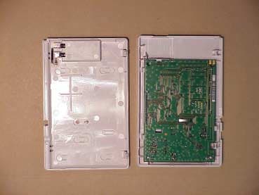
Click to zoom
Application Details
- Equipment Class
- DSC - Part 15 Security/Remote Control Transmitter
- Date of Grant
- Jun 07, 2001
- Application Purpose
- Original Equipment
- Date of Application
- Feb 23, 2001
- Equipment Note
- remote wireless keypad device
- Frequency Range
- 345.00000000 - 345.00000000
- Company
- Ademco Inc.
- Country
- United States
Documents & Files
Document Text
Text extracted from the exhibit documents filed with the FCC. Open a document above to read the original.
Cover Letter(s)
To whom it may concern: Here is the timing diagram that you requested ( correspondence ref #: 18479 ) we ordinarily only send you the duty cycle calculation ( typically our EXHIBIT 3-1 ) Regards, Greg Barbato for Ken Addy
Operational Description
DUTY CYCLE CALCULATION EXHIBIT 3-1 CFS8DL5839US The 5839US uses 4.5 K Baud Phase Encoded (Manchester) data, with a maximum bit cell interval of 223 uSec. The 5839US transmits a 16 bit preamble, ( 15 bits + one sync bit ) and 96 bits of control data. For a total of 112 bits of information. the total message is 25 mSec. long. The message is repeated five (5) times, every 120 mSec. (MIN) Therefore: the message is only sent once every 100 mSec. i.e.; 25 mSec. / 100 mSec. = .25 Further the Manchester has an inherent duty cycle of 50% making the total transmitter duty cycle: .25 X .50 = .125 X 100 = 12.5 % total transmitter on time.
Operational Description
EXHIBIT 1 CFS8DL5839US Functional Description The 5839US fixed transceiver is compatible with Ademco’s wireless 5800 alarm system. It is used in conjunction with portable transmitters (e.g. 5804) or portable transceivers (e.g. 5804BD). This allows remote control of the alarm system and provides remote indication that a control instruction has been enacted. These messages are transmitted at 345Mhz +/-82kHz using on-off keyed AM modulation. The 5839US does not send a regular supervision or check-in message, it transmits no other messages except those which are a confirmation of reception of manually initiated control messages which have been received from portable remote control transmitters and control and alarm messages.
Schematics
2 45 3 1
Test Report
EXHIBIT 5-1 CFS8DL5839US Report of Measurements. Measurements were made at Ademco 's Measurement Facility at 160 Eileen Way , Syosset , NY 11791 , FCC Registration number : 90421. Measurements were made in accordance with the procedures and reporting requirements of ANSI C63.4-1992. The Test Set-Up (C63.4 section 10.1.3) is shown in the attached drawing. The sequence of testing (C63.4 section 10.1.7) for radiated emissions is as follows: A preliminary scan was conducted with the receiver antenna close to the EUT in order to identify the emission characteristics of the EUT (C63.4 section 8.3.1.1). The antenna and EUT were then placed at the proper separation with the EUT positioned on a non-conducting turntable. The EUT was rotated on the turntable to maximize the received signal strength, then the receiver antenna height was varied to further maximize the received reading. Thereafter, the device was again rotated to a peak output position and the antenna height was re-adjusted for maximum received signal. This procedure was re-iterated until there was no further increase in signal level. This procedure was performed with the EUT rotating in three orthogonal planes (C63.4 section 13.1.4.1) to generate a final maximum reading which is recorded on the radiated emissions result sheet. Similar measurements were made on the receiver to ensure compliance as an unintentional radiator. See Exhibit 6 for list of test equipment (C63.4 section 10.1.4). Note, Spectrum Analyzer resolution bandwidths set as follows; (Video Bandwidth set greater than RBW) - For occupied bandwidth measurements, RBW = 100kHz, (This is in accordance with the minimum RBW allowed by C63.4, which requires RBW greater than 5% of the FCC required occupied bandwidth spec of 0.25% of center frequency). - For radiated emissions below 1 GHz, the RBW = 100kHz. Detector function set to peak. - For radiated emissions above 1 GHz, the RBW = 1MHz. Detector function set to peak. OCCUPIED BANDWIDTH is shown on attached plot. RADIATED EMISSIONS are recorded on attached sheet.
Test Report
Frequency (MHz) Antenna Polarity ( V-H ) Meter Reading (dB uV) Cable/Amp Factor ( dB ) Antenna Factor (dB/M) Converted Reading ( uV/M ) Duty Cycle ( % ) Corrected Reading ( uV/M ) Limit @ 3 Meter ( uV/M ) 30 H 12.5 729 345 V 73.33 1.5 15.131,369.0 12.5 3,921.1 7,290 690 V 38.67 2.1 20.61,170.8 12.5 146.4 729 1035 H 23.00 2.6 24.0302.0 12.5 37.8 500 1380 H 39.50 3.0 27.93,311.3 12.5 413.9 500 1725 V 39.67 3.4 30.04,503.0 12.5 562.9 729 2070 H 35.50 3.7 28.02,291.0 12.5 286.4 729 2415 H 23.00 4.0 28.8616.6 12.5 77.0 729 2760 H 24.50 4.3 30.0871.0 12.5 108.9 729 3105 H 24.50 4.5 30.7996.0 12.5 124.5 729 3450 H 23.00 4.8 31.1881.0 12.5 110.1 729 4000 H 12.5 729 NOTES: FEBRUARY, 09, 2001 GREG BARBATO KEN ADDY DATE:____________________ TESTED BY:_________________________APPROVED BY:________________________ ADEMCO 5839US (TRANSMITTER) TEST SAMPLE (model): _______________________________________________________________________________ TEST METHOD: ANSI C63.4-1992 TEST SPECIFICATION: FCC PART 15, SUBPART C. NOTES: 1) Fo= 345 MHZ 2) DETECTOR = PEAK. 3) FREQUENCY RANGE SCANNED TO 4 GHz. (METER READING +CABLE /AMP FACTOR +ANTENNA FACTOR) 4) CONVERTED READING = 10 20 5) CORRECTED READING = CONVERTED READING X DUTY CYCLE 6) SIX HIGHEST EMISSIONS RECORDED. ALARM DEVICE MANUFACTURING COMPANY 165 EILEEN WAY CFS8DL5839US SYOSSET, NY 11791 FCC ID#____________________
Contact Information
Applicant
Christian Fouth(Sr. Wireless Certification Engineer)
Technical Contact
Alarm Device Manufacturing CompanyKen L Addy
[email protected]516-921-6704
A Division of Pittway Corporation · Syosset, New York · United States
Non-Technical Contact
Alarm Device Manufacturing CompanyKen L Addy
[email protected]516-921-6704
Test Firm
AdemcoKenneth Addy
Technical Specifications
| # | Rule Parts | Frequency Range | Power Output | Tolerance |
|---|---|---|---|---|
| 1 | 15C | 345 MHz - 345 MHz | - | Hz |
Other Applications from Ademco Inc.

CFS8DL5800MINIV
Jan 28, 2026Wireless Alarm Transmitter
Equipment Class
DXX - Part 15 Low Power Communication Device Transmitter
CFS8DLWTS800
Jan 12, 2026Wireless Alarm Transmitter
Equipment Class
DTS - Digital Transmission SystemCFS8DLCAMWEWI1
Jul 25, 2024VX5 HD Indoor Camera
Equipment Class
DTS - Digital Transmission System
CFS8DLCAMWEWO1
Sep 17, 2023VX3 HD Outdoor Camera
Equipment Class
NII - Unlicensed National Information Infrastructure TX
CFS8DLLMD500A
Jul 20, 2023Wireless door/window contact
Equipment Class
DTS - Digital Transmission System