CFS8DL5878Wireless Key Transmitter
Ademco Inc.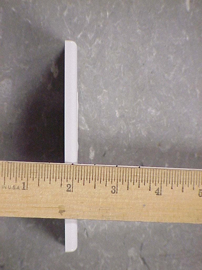
Click to zoom
Application Details
- Equipment Class
- DSC - Part 15 Security/Remote Control Transmitter
- Date of Grant
- May 31, 2006
- Application Purpose
- Original Equipment
- Date of Application
- May 31, 2006
- Equipment Note
- Wireless Key Transmitter
- Frequency Range
- 345.00000000 - 345.00000000
- Company
- Ademco Inc.
- Country
- United States
Documents & Files
Document Text
Text extracted from the exhibit documents filed with the FCC. Open a document above to read the original.
Block Diagram
EXHIBIT 2-2 BLOCK DIAGRAM CFS8DL5878 / 573F-5878 SECTION 2.1033(b) SECTION 2.1033(b) (3) Block Diagram. 5878 Honeywell 5878 Single Chip Transmitter "IC1" (U1) is the Encoder ( 'Micro' ) U2 is the single chip transmitter.
Cover Letter(s)
reply1 RE: Honeywell FCC ID: CFS8DL5878 (FCC & IC Review) After a review of the submitted information, I have a few comments on the above referenced Application. > 1) Operational description cites there are not supervisory transmissions, > but duty cycle information presents information for this. Please correct/clarify as necessary. Tim, The Operational Description is correct. There are NO supervisory transmissions. What "EXHIBIT 3-2" is showing is what a "supervisory transmission" would look like if there was one - this was included for explanation purposes only. Sorry for the confusion. > 2) FCC desires actual test photographs and not simply a test diagram. Please provide test > configuration photographs on the test site if available. Please look at "EXHIBIT 5-2A" for the close-up & testing photos. > 3) Test report uses a 10% duty factor. However the operational description mentions both a 10% and > 14.3% version. Worse case would be utilizing 14.3% duty factor. Please review/correct as necessary. Please look at "EXHIBIT 5-3A" > 4) Please note that given 3) above, it appears that using 10% that points at 2070 MHz may exceed > the limit using 14.3%. Please review. FYI: Tim found a loose cap resoldered EXHIBIT 5-3A is now current. > 5) The users manual appears to be missing information required by 15.21. Please correct. Please look at "EXHIBIT 7A" > For IC > 7) Label does not show that applicant as certified is given on the label. Please review. Please look at "EXHIBIT 8A" > 8) FYI....In the future, please ensure BW for IC is measured using a VBW > 3 * RBW. Additionally, > most are now providing a separate occupied bandwidth plot for IC that appropriately measures > using the spectrum analyzers 99% feature or the methods provided in the attached document. > Please consider this in future applications. Will Impliment. Page 1
ID Label/Location Info
EXHIBIT 8 FCC & IC LABEL INFORMATION CFS8DL5878 / 573F-5878 Engineers drawing of label location & label text. FCC ID: CFS8DL5878 This device complies with Part 15 of the FCC Rules. Operation is subject to the following two conditions: (1) this device may not cause harmful interference, and (2) this device must accept any interference received, including interference that may cause undesired operation. IC: 573F-5878 Honeywell International Inc. MODEL: 5878
Operational Description
EXHIBIT 1-1 CFS8DL5878 / 573F-5878 FUNCTIONAL DESCRIPTION The 5878 is a wall plate type transmitter, used to send arm, disarm, and panic messages to Ademco alarm systems in the same manor as a key-fob. It may also be used to perform auxiliary control of lighting or garage doors, through the system.
Operational Description
EXHIBIT 2-1 CFS8DL5878 / 573F-5878 CIRCUIT DESCRIPTION The RF transmitter portion of the 5878 wall-plate is a single chip (U2) phase locked transmitter, using crystal, XTAL1 as its FDE. L1 & C5 make up the external circuit for the chips internal PA, and C6, L2, C7 provide harmonic suppression, while C8, matchs the printed antenna. Encoder "IC1" (U1) controls all functions of the wall plate transmitter. The 5878 sends no supervision messages.
Operational Description
EXHIBIT 3-1 TIMING / DUTY CYCLE CALCULATION CFS8DL5878 / 573F-5878 Section 15.255(b) Section 15.255(b), when the radiated emission limits are expressed in terms of the average value of the emission, and pulsed operation is employed, the measurement field strength shall be determined by averaging over one complete pulse train, including blanking intervals, as long as the pulse train does not exceed 0.1 seconds. The exact method of calculating the average field strength shall be submitted with any application for certification. Standard 5800 (10%) Duty Cycle Calculation Message protocol, timing and duty cycle calculation: The data output is phase-encoded Manchester that has inherent 50% duty cycle and consists of 64 bits per word sent at a nominal data rate of 3.7 kb/s (3.2kb/s min to 4.2kb/s max). Therefore the duty cycle is calculation is as follows: The word format consists of 64 bits, The duration of each bit is 312.5 uSec max. The duty cycle over a 100 mSec measuring period is calculated as follows: Duty cycle = Actual RF transmission ON time / 100 mSec Actual transmission ON time = 64 bits X 50% X 312.5 uSec = 10 mSec Therefore duty cycle = 10 / 100 mSec = .10 = 10%, and peak to average field strength is 20 db. Total on-air time for a supervision transmission is: 64 X 312.5 uSec + (5 X 150 mSec) = 0.77 seconds The group of six transmissions is repeated twice, with the second group delayed from the first by a max time of 2 seconds. The worst case on-air time is 1.54 + 2 = 3.54 seconds Summary: - Duty cycle = 10% On airtime = 3.54 seconds EXHIBIT 3-1 DUTY CYCLE CALCULATION CFS8DL5878 / 573F-5878 ROLLING CODE ENCRYPTION (14.3%) - HCS 300 ENCODER MESSAGE T E 3+1+10+11+4 = 29 Calculation is basis of worst case data content in order to maximize duty cycle On-time. Message packet is as follows: 2.3mS preamble 1.0ms header 62 bits at data '0' 4 bits at data '1' 3.9mS guard Total Message packet Time ( (23 + 10 + (66X3) )X 0.1 ) + 3.0 = 23.1 + 3.9 = 27.0 mS Total Message packet On Time (23X.1) + ( (66X2) X 0.1 ) = (155 X 0.1) = 15.5 mS Therefore the duty cycle for the peak to average power conversion is: 15.5 Duty Cycle = = 14.3 % (27.0 X 4)
Operational Description
EXHIBIT 3-2 DUTY CYCLE TIMING DIAGRAMS CFS8DL5878 / 73F-5878 Section 15.255(b) Section 15.255(b), The exact method of calculating the average field strength shall be submitted with any application for certification. 5878 ( 10% ) Messages: Rolling code encryption ( 14.3%) with the HCS 300 Encoder:
Test Report
EXHIBIT 5-1 CFS8DL5878 / 573F-5878 Report of Measurements. Measurements were made at Honeywells Measurement Facility at 160 Eileen Way , Syosset , NY 11791 , FCC Registration number : 90421. IC Registration number : 4338 Measurements were made in accordance with the procedures and reporting requirements of ANSI C63.4-2003. The Test Set-Up (C63.4 section 10.1.3) is shown in the attached photograph. The sequence of testing (C63.4 section 10.1.7) for radiated emissions is as follows: A preliminary scan was conducted with the receiver antenna close to the EUT in order to identify the emission characteristics of the EUT (C63.4 section 8.3.1.1). The antenna and EUT were then placed at the proper separation with the EUT positioned on a non-conducting turntable. The EUT was rotated on the turntable to maximize the received signal strength, then the receiver antenna height was varied to further maximize the received reading. Thereafter, the device was again rotated to a peak output position and the antenna height was re-adjusted for maximum received signal. This procedure was re-iterated until there was no further increase in signal level. This procedure was performed with the EUT rotating in three orthogonal planes (C63.4 section 13.1.4.1) to generate a final maximum reading which is recorded on the radiated emissions result sheet. Similar measurements were made on the receiver to ensure compliance as an unintentional radiator. See Exhibit 6 for list of test equipment (C63.4 section 10.1.4). Note, Spectrum Analyzer resolution bandwidths set as follows; Video Bandwidth = 3 X RBW - For radiated emissions below 1 GHz, the RBW = 100kHz. Detector function set to peak. - For radiated emissions above 1 GHz, the RBW = 1MHz. Detector function set to peak. - For occupied bandwidth measurements, RBW = 100kHz, (This is in accordance with the minimum RBW allowed by C63.4, which requires RBW greater than 5% of the FCC required occupied bandwidth spec of 0.25% of center frequency i.e.; 345 MHz X 0.25% = 862,500 KHz X 5% = 43,125 KHz min RBW ). THE TEST SETUP PHOTOS are shown in EXHIBIT 5-2. TX RADIATED EMISSIONS are recorded in EXHIBIT 5-3. TX OCCUPIED BANDWIDTH is shown in EXHIBIT 5-4.
Test Report
HONEYWELL SECURITY & CUSTOM ELECTRONICS 165 EILEEN WA Y SYOSSET, NY 11791EXHIBIT 5-3 FCC ID # CFS8DL5878 Date : 5/30/2006 Tested by :Y. Mohammed Approved by :K.Addy Test Sample (model) : 5878 Test method: ANSI C63.4 - 2003 Test specification: FCC Part 15, Sub-part C Notes: (1) Fo = 345MHz. (2) Detector = Peak (3) Frequency range scanned to 4 GHz. Emissions not reported were more than 20dB below the specified unit. [(Meter reading + Cable/Amp factor + Antenna factor) / 20 )] (4) Conv. Reading = 10 (5) Corr. Reading = Conv. Reading X Duty Cycle (6) Six Highest Emissions Recorded Freq. (MHz) Antenna Polarity (V/H) Meter Reading (dB uV) Cable/Amp Factor (dB) Antenna Factor (dB/m) Conv. Reading (uV/M) Duty Cycle (%) Corr. Reading (uV/M) Limit @ 3M (uV/M) 30 CABLE "A"BICONILOG729 345H74.601.214.7833806.514.3%4834.37292 690H40.001.819.101109.214.3%158.6729 1035H30.002.222.70555.914.3%79.5500 1380H33.002.524.961054.414.3%150.8500 1725H39.002.827.552934.314.3%419.6729 2070H41.003.029.524742.414.3%678.2729 2415H34.003.331.132639.414.3%377.4729 2760 H 32.003.7 31.502290.914.3%327.6500 3105H32.004.131.612429.414.3%347.4729 3450H30.004.432.222142.914.3%306.4729 4000 CABLE "A"BICONILOG HONEYWELL SECURITY & CUSTOM ELECTRONICS 165 EILEEN WA Y SYOSSET, NY 11791EXHIBIT 5-3 FCC ID # CFS8DL5878 Date : 5/30/2006 Tested by :Y. Mohammed Approved by :K.Addy Test Sample (model) : 5878 Test method: ANSI C63.4 - 2003 Test specification: FCC Part 15, Sub-part C Notes: (1) Fo = 345MHz. (2) Detector = Peak (3) Frequency range scanned to 4 GHz. Emissions not reported were more than 20dB below the specified unit. [(Meter reading + Cable/Amp factor + Antenna factor) / 20 )] (4) Conv. Reading = 10 (5) Corr. Reading = Conv. Reading X Duty Cycle (6) Six Highest Emissions Recorded Freq. (MHz) Antenna Polarity (V/H) Meter Reading (dB uV) Cable/Amp Factor (dB) Antenna Factor (dB/m) Conv. Reading (uV/M) Duty Cycle (%) Corr. Reading (uV/M) Limit @ 3M (uV/M) 30 CABLE "A"BICONILOG729 345H74.601.214.7833806.510.0%3380.67292 690H40.001.819.101109.210.0%110.9729 1035H30.002.222.70555.910.0%55.6500 1380H33.002.524.961054.410.0%105.4500 1725H39.002.827.552934.310.0%293.4729 2070H41.003.029.524742.410.0%474.2729 2415H34.003.331.132639.410.0%263.9729 2760 H 32.003.7 31.502290.910.0%229.1500 3105H32.004.131.612429.410.0%242.9729 3450H30.004.432.222142.910.0%214.3729 4000 CABLE "A"BICONILOG
Test Report
5878 OCCUPIED BANDWIDTH RBW = 100 KHz VBW = 100KHz OBW = 623 KHz
Test Report
EXHIBIT 6 TEST EQUIPMENT USED CFS8DL5878 / 573F-5878 Section 15.231 and ANSI C63.4 Section 15.231, per C63.4. This is a list of all test equipment used. Test Equipment list 1. Antenna: BICONOLOG S/N: 00029290 Cal. on: 09/12/05 Cal. due: 09/12/06 2. Spectrum Analyzer H. P. 8563E S/N:3246A00232 Cal. on: 08/20/05 Cal. due: 08/20/06
Contact Information
Applicant
Christian Fouth(Sr. Wireless Certification Engineer)
Technical Contact
Honeywell International Inc.Ken Addy
[email protected]516-921-6704
165 Eileen Way · Syosset, New York · United States
Test Firm
Honeywell International Inc.Kenneth Addy
Technical Specifications
| # | Rule Parts | Frequency Range | Power Output |
|---|---|---|---|
| 1 | 15.231 | 345 MHz - 345 MHz | - |
Other Applications from Ademco Inc.

CFS8DL5800MINIV
Jan 28, 2026Wireless Alarm Transmitter
Equipment Class
DXX - Part 15 Low Power Communication Device Transmitter
CFS8DLWTS800
Jan 12, 2026Wireless Alarm Transmitter
Equipment Class
DTS - Digital Transmission SystemCFS8DLCAMWEWI1
Jul 25, 2024VX5 HD Indoor Camera
Equipment Class
DTS - Digital Transmission System
CFS8DLCAMWEWO1
Sep 17, 2023VX3 HD Outdoor Camera
Equipment Class
NII - Unlicensed National Information Infrastructure TX
CFS8DLLMD500A
Jul 20, 2023Wireless door/window contact
Equipment Class
DTS - Digital Transmission System