CFS8DL5882APSecurity System Device
Ademco Inc.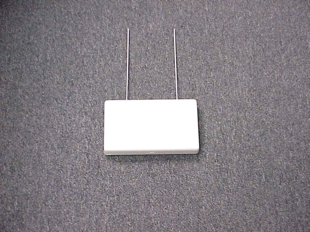
Click to zoom
Application Details
- Equipment Class
- DSR - Part 15 Remote Control/Security Device Transceiver
- Date of Grant
- Dec 11, 2005
- Application Purpose
- Original Equipment
- Date of Application
- Nov 29, 2005
- Equipment Note
- Security System Device
- Frequency Range
- 315.00000000 - 315.00000000
- Company
- Ademco Inc.
- Country
- United States
Documents & Files
Document Text
Text extracted from the exhibit documents filed with the FCC. Open a document above to read the original.
Users Manual
5 GREEN LED: NORMALLY OFFONE SHORT FLASH - RF MESSAGE DECODEDONE LONGER FLASH - COMMAND RECEIVED FROM CONTROLNOTES:WHEN AN ENCRYPTED TRANSMITTER IS SUCCESSFULLY ENROLLED,LED FLASHES A NUMBER OF TIMES THAT IS EQUAL TO THE SPACE AVAILABLE FOR ADDITIONAL ENCRYPTED KEYS.THE GREEN LED IS ALSO USED WHEN CHECKING ENCRYPTED KEY SPACE AVAILABLE AND PERFORMING DELETIONS. SEE ENCRYPTEDKEYS DESCRIPTION FOR DETAILS. NOTE: WHEN CIRCUIT BOARD IS MOUNTED IN CONTROL'S CABINET, GROUNDING LUGS(2) PROVIDED MUST BE INSERTED IN LEFT- HAND TERMINALS OF ANTENNA BLOCKS AND SECURED TO CABINET (SEE RECEIVER'S AND CONTROL'S INSTRUCTIONS).WHEN BOARD IS MOUNTED IN A SEPARATECABINET (COMMERCIAL FIRE APPLICATION),DO NOT USE THE GROUNDING LUGS.TO RELEASE CIRCUIT BOARD, BEND BACKBOTTOM TABS (2). FOR COMMERCIAL FIREAPPLICATION. USE TWO SCREWS(NOT SUPPLIED) WITH INSULATING WASHERSBENEATH THE HEADS. TO MOUNT BOARD INSEPARATE CABINET.(SEE RECEIVER'S INSTRUCTIONS). MOUNTING HOLES CIRCUIT BOARD INTERFERENCE INDICATOR LED PLUG & SOCKET WIRINGOPENING YELLOWREDBLACKGREEN FCC ID CFS8DL5882A P . USE MAX. OF 220 ft. (67m) OF #22 (0.64mm) WIREOR 550 ft. (168m) OF #18 (1mm) WIRE FOR EACH RUN. 20 ft. MAX. IN COMMERCIAL FIRE INSTALLATIONS.(SEE RECEIVER'S INSTRUCTIONS). TO CONTROL'S KEYPADTERMINALS. EACH RECEIVERMUST BE ON INDIVIDUALHOME RUN. THIS DEVICE COMPLIES WITH PART 15 OF FCC RULES.OPERATION IS SUBJECT TO THE FOLLOWING TWOCONDITIONS: (1) THIS DEVICE MAY NOT CAUSE HARMFULINTERFERENCE, AND (2) THIS DEVICE MUST ACCEPT ANYINTERFERENCE RECEIVED, INCLUDING INTERFERENCETHAT MAY CAUSE UNDESIRED OPERATION. DIP SWITCH #5ON: FOR USE IN COMMERCIAL FIRE APPLICATIONS.(SEE THE RECEIVER'S INSTRUCTIONS). OFF: USE IN NON-COMMERCIAL FIRE INSTALLATIONS. SWITCH RECEIVER ADDRESS SETTINGS POSITION (“—” means “OFF”) 01234567 5 (SEE TEXT ABOVE) 4 — ON — ON — ON — ON 3 —— ON ON —— ON ON 2 ———— ON ON ON ON 1 54321 ON OFF MUST BE IN OFF POSITION DETAIL A FRONT AND REAR TAMPER 5881ENHC ONLY SEEDETAIL A 5881EN SERIES 5881ENL 5881ENM 5881ENHC 5881ENH DIP SWITCH: WHITE AREAS = SWITCH HANDLESPOSITION 2-4: DETERMINE RECEIVER'S ADDRESSCONSULT CONTROL'S INSTRUCTIONS FOR ADDRESS TO USE.DIP SWITCH BELOW SHOWN SET FOR ADDRESS "0". BACK OF PC BOARD FRONT OF PC BOARD ANTENNAS INSERT IN RIGHT-HAND TERMINALS DIP SWITCH 5881EN-SOC-V1 Figure 3: Summary of Connections, 5881EN Series RF Receivers 6 FCC ID CFS8DL5882AP FEDERAL COMMUNICATIONS COMMISSION (FCC) STATEMENT This equipment has been tested to FCC requirements and has been found acceptable for use. The FCC requires the following statement for your information: This equipment generates and uses radio frequency energy and if not installed and used properly, that is, in strict accordance with the manufacturer's instructions, may cause interference to radio and television reception. It has been type tested and found to comply with the limits for a Class B computing device in accordance with the specifications in Part 15 of FCC Rules, which are designed to provide reasonable protection against such interference in a residential installation. However, there is no guarantee that interference will not occur in a particular installation. If this equipment does cause interference to radio or television reception, which can be determined by turning the equipment off and on, the user is encouraged to try to correct the interference by one or more of the following measures: • If using an indoor antenna, have a quality outdoor antenna installed. • Reorient the receiving antenna until interference is reduced or eliminated. • Move the radio or television receiver away from the receiver/control. • Move the antenna leads away from any wire runs to the receiver/control. • Plug the receiver/control into a different outlet so that it and the radio or television receiver are on different branch circuits. If necessary, the user should consult the dealer or an experienced radio/television technician for additional suggestions. The user or installer may find the following booklet prepared by the Federal Communications Commission helpful: "Interference Handbook" This booklet is available under Stock No. 004-000-00450-7 from the U.S. Government Printing Office, Washington, DC 20402. The user shall not make any changes or modifications to the equipment unless authorized by the Installation and Setup Guide or User Guide. Unauthorized changes or modifications could void the user's authority to operate the equipment. WARNING THE LIMITATIONS OF THIS WIRELESS ALARM SYSTEM While this System is an advanced wireless security system, it does not offer guaranteed protection against burglary, fire or other emergency. Any alarm system, whether commercial or residential, is subject to compromise or failure to warn for a variety of reasons. For example: • Intruders may gain access through unprotected openings or have the technical sophistication to bypass an alarm sensor or disconnect an alarm warning device. • Intrusion detectors (e.g., passive infrared detectors), smoke detectors, and many other sensing devices will not work without power. Battery-operated devices will not work without batteries, with dead batteries, or if the batteries are not put in properly. Devices powered solely by AC will not work if their AC power supply is cut off for any reason, however briefly. • Signals sent by wireless transmitters may be blocked or reflected by metal before they reach the alarm receiver. Even if the signal path has been recently checked during a weekly test, blockage can occur if a metal object is moved into the path. • A user may not be able to reach a panic or emergency button quickly enough. • While smoke detectors have played a key role in reducing residential fire deaths in the United States, they may not activate or provide early warning for a variety of reasons in as many as 35% of all fires, according to data published by the Federal Emergency Management Agency. Some of the reasons smoke detectors used in conjunction with this System may not work are as f…
Text truncated - open the document above for the full version.
Cover Letter(s)
COVER LETTER Federal Communications Commission Honeywell International Inc. Equipment Approval Services Radio Engineering PO BOX 358315 160 Eileen Way Pittsburgh, PA 15251 5315 Syosset, NY 11791 November, 30, 2005 Subject: Application for Certification of Honeywell’s Security Device type: 5882AP FCC ID: CFS8DL5882AP Dear Sir or Madam: Please find (e-filed) a 731 application form and 159 payment form (via credit card) for submittal of this product. The following exhibits were also uploaded to your site: • functional description • circuit description • block diagram • schematic • external and internal photos • product test report • users manual • label This is for the certification of Honeywell’s 5882AP receiver under FCC rules and regulations Part 15 subpart C. As this is a receiver please note that: 1) there is no EXHIBIT 3-1 or 3-2 (duty cycle / timing calculation) , 2) the emissions report (EXHIBIT 5-3) is for an unintentional radiator, and 3) there is no EXHIBIT 5-4 (occupied bandwidth) report. If you have any questions or require additional information, please contact me at 516-921-6704 ,Ext. 6920 Regards, Greg Barbato for Ken Addy Director Radio Engineering
Cover Letter(s)
Dear Mr. Leimer, You wrote: To: Ken Addy, Honeywell International Inc. From: Andrew Leimer [email protected] FCC Application Processing Branch Re: FCC ID CFS8DL5882AP Applicant: Honeywell International Inc. Correspondence Reference Number: 30129 731 Confirmation Number: EA295981 1) Verify that this device does not have any transmit capability. This is only a receiver. Mr. Leimer, This device is only a receiver and does not have any transmit capability. It is the receiver our system uses to listen for the 315 MHz transmitters. Best Regards, Greg Barbato for Ken Addy (516) 921-6704 Ext 6920
Operational Description
EXHIBIT 1-1 CFS8DL5882AP FUNCTIONAL DESCRIPTION The 5882AP is a 315 MHz version of our 5882-4 receiver;( FCC ID: CFS8DL5882-4) it is identical in function and operation with the exception of the operating frequency which is 315 MHz. to allow reception of our 315 MHz transmitters such as the CFS8DL5816AP, and CFS8DL5804AP, etc.
Operational Description
EXHIBIT 2-1 CFS8DL5882AP CIRCUIT DESCRIPTION The 315 Mhz RF signal enters the receiver at the diversity antennas ANT1 & ANT2. CR1 & CR2 switch ANT1 & ANT2 under the control of MICROPROCESSOR U8. The LNA ( Q3,L10,L5,etc. ) improves the noise figure. RECEIVER CHIP U1 provides all the basic receiver functions. FL1 & FL2 provide IF band pass. The L.O. is made up of Q1, L14, etc., the FREQUENCY DETERMINING ELEMENT is: Y1 ( 50.716666 Mhz ), the 6th. harmonic of Y1 is: 304.3 Mhz this is low side injection for the 315.0 Mhz input. SIGNAL PROCESSING is accomplished via U2 & U3 and their associated components. Y2 ( 10.073 Mhz ) is the source of the microprocessors clock, and is not part of the RF path. Other peripheral components include: VOLTAGE REGULATION / CONTROL: U5, U7, U11, etc.
Test Report
EXHIBIT 5-1 Report of Measurements. CFS8DL5882AP Section 15.231 and ANSI C63.4 Measurements were made at Honeywell's Measurement Facility at 160 Eileen Way, Syosset , NY 11791 , FCC Registration number : 156835. Measurements were made in accordance with the procedures and reporting requirements of ANSI C63.4-1992. The Test Set-Up (C63.4 section 10.1.3) is shown in the attached drawing; EXHIBIT 5-2. The sequence of testing (C63.4 section 10.1.7) for radiated emissions is as follows: A preliminary scan was conducted with the receiver antenna close to the EUT in order to identify the emission characteristics of the EUT (C63.4 section 8.3.1.1). The antenna and EUT were then placed at the proper separation with the EUT positioned on a non-conducting turntable. The EUT was rotated on the turntable to maximize the received signal strength, then the receiver antenna height was varied to further maximize the received reading. Thereafter, the device was again rotated to a peak output position and the antenna height was re-adjusted for maximum received signal. This procedure was re- iterated until there was no further increase in signal level. This procedure was performed with the EUT rotating in three orthogonal planes (C63.4 section 13.1.4.1) to generate a final maximum reading which is recorded on the radiated emissions result sheet. Similar measurements were made on the receiver to ensure compliance as an unintentional radiator. See EXHIBIT 6 for list of test equipment (C63.4 section 10.1.4). Note, Spectrum Analyzer resolution bandwidths set as follows; (Video Bandwidth set greater than RBW) - For occupied bandwidth measurements, RBW = 100kHz, (This is in accordance with the minimum RBW allowed by C63.4, which requires RBW greater than 5% of the FCC required occupied bandwidth spec of 0.25% of center frequency). - For radiated emissions below 1 GHz, the RBW = 100kHz. Detector function set to peak. - For radiated emissions above 1 GHz, the RBW = 1MHz. Detector function set to peak. RADIATED EMISSIONS are recorded in EXHIBIT 5-3 (RX).
Test Report
EXHIBIT 5-5 CFS8DL5882AP Section 15.231 (Periodic operation above 70 MHz.) In addition to the provisions of Section 15.205, the field strength of emissions from intentional radiators operated under this Section shall not exceed the following: Frequency Fundamental Spurious (MHz) (microvolts/meter) (microvolts/meter) 260 - 470 3,750 to 12,500 ** 375 to 1,250 ** NOTE: ** linear interpolations NOTES: (1) The above field strength limits are specified at a distance of 3 meters. The tighter limits apply at the band edges. (2) Intentional radiators operating under the provisions of this Section shall demonstrate compliance with the limits on the field strength of emissions, as shown in the above table, based on the average value of the measured emissions. As an alternative, compliance with the limits in the above table may be based on the use of measurement instrumentation with a CISPR quasi-peak detector. The specific method of measurement employed shall be specified in the application for equipment authorization. If average emission measurements are employed, the provisions in Section 15.35 for averaging pulsed emissions and for limiting peak emissions apply. Further, compliance with the provisions of Section 15.205 shall be demonstrated using the measurement instrumentation specified in that section. (3) The limits on the field strength of the spurious emissions in the above table are based on the fundamental frequency of the intentional radiator. Spurious emissions shall be attenuated to the average (or, alternatively, CISPR quasi-peak) limits shown in this table or to the general limits shown in Section 15.209, whichever limit permits a higher field strength. (4) Fo = 315MHz.LO = 304.3MHz(315-10.7 ) Crystal frequency = 50.71666 (5) Detector = Peak (6) Frequency range scanned to 4 GHz. (Emissions not reported were more than 20dB below the specified limit). [(Meter reading + Cable/Amp factor + Antenna factor) / 20 )] (7) Conv. Reading = 10 (8) Corr. Reading = Conv. Reading X Duty Cycle (9) Date : 5/10/2005 Tested by :Y. Mohammed Approved by : Ken Addy Freq. (MHz) Antenna Polarity (V/H) Meter Reading (dB uV) Cable/Amp Factor (dB) Antenna Factor (dB/M) Conv. Reading (uV/M) Duty Cycle (%) Corr. Reading (uV/M) Limit @ 3M (uV/M) 30 CABLE "A"BICONOLOG604 50.716h24.000.0015.6095.5100.0%95.5100 101.433h24.000.7010.2155.7100.0%55.7150 152.150h24.000.8013.4181.4100.0%81.4150 202.867h24.001.0011.6367.8100.0%67.8150 253.583h24.001.1012.0371.9100.0%71.9200 304.300h24.001.2013.3284.3100.0%84.3200 355.017h24.001.3015.06104.2100.0%104.2200 405.733 h24.00 1.40 16.43123.5100.0%123.5200 456.450h24.001.5016.40124.5100.0%124.5200 507.167h24.001.5516.73130.0100.0%130.0200 557.883h24.001.6017.97150.8100.0%150.8200 608.600h24.001.8018.1156.7100.0%156.7200 4000 CABLE "A"BICONOLOG
Test Report
EXHIBIT 6 TEST EQUIPMENT USED CFS8DL5882AP Section 15.231 and ANSI C63.4 Section 15.231, per C63.4 section 10.1.4. This is a list of all test equipment used. Test Equipment list 1. Antenna: BICONOLOG S/N: 00029290 Cal. on: 09/14/04 Cal. due: 09/14/05 2. Spectrum Analyzer H. P. 8563E S/N:3246A00232 Cal. on: 08/23/04 Cal. due: 08/23/05
Test Setup Photos
EXHIBIT 5-2 PICTURE OF THE TEST SETUP CFS8DL5882AP SECTION 2.1093 (c) SECTION 2.1093 (c) Photo of the test setup shall be provided.
Contact Information
Applicant
Christian Fouth(Sr. Wireless Certification Engineer)
Technical Contact
Honeywell International Inc.Ken L Addy
[email protected]516-921-6704
165 Eileen Way · Syosset, New York · United States
Non-Technical Contact
Honeywell International Inc.Ken L Addy
[email protected]516-921-6704
Test Firm
Honeywell International Inc.Kenneth Addy
Technical Specifications
| # | Rule Parts | Frequency Range | Power Output |
|---|---|---|---|
| 1 | 15B | 315 MHz - 315 MHz | - |
Other Applications from Ademco Inc.

CFS8DL5800MINIV
Jan 28, 2026Wireless Alarm Transmitter
Equipment Class
DXX - Part 15 Low Power Communication Device Transmitter
CFS8DLWTS800
Jan 12, 2026Wireless Alarm Transmitter
Equipment Class
DTS - Digital Transmission SystemCFS8DLCAMWEWI1
Jul 25, 2024VX5 HD Indoor Camera
Equipment Class
DTS - Digital Transmission System
CFS8DLCAMWEWO1
Sep 17, 2023VX3 HD Outdoor Camera
Equipment Class
NII - Unlicensed National Information Infrastructure TX
CFS8DLLMD500A
Jul 20, 2023Wireless door/window contact
Equipment Class
DTS - Digital Transmission System