CFS8DL5897Microwave/PIR Motion Sensor
Ademco Inc.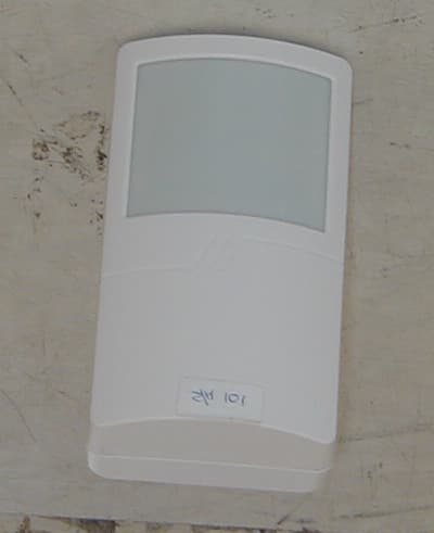
Click to zoom
Application Details
- Equipment Class
- DSC - Part 15 Security/Remote Control Transmitter
- Date of Grant
- Jan 14, 2002
- Application Purpose
- Original Equipment
- Date of Application
- Jan 14, 2002
- Equipment Note
- Microwave/PIR Motion Sensor
- Frequency Range
- 345.00000000 - 345.00000000
- Company
- Ademco Inc.
- Country
- United States
Documents & Files
Document Text
Text extracted from the exhibit documents filed with the FCC. Open a document above to read the original.
Cover Letter(s)
RE: ADEMCO FCC ID: CFS8DL5897 15 th January, 2002 Dear Tim: Your recent review of the submitted information on the above referenced application raised some issues. Here is our response to each of the seven issues raised. 1) Please provide a photograph with the shield removed for the attached file, It does not appear that one was provided with the original files. An additional file (Internal Photo - Shield Removed.JPG) containing the required photograph has been uploaded to the ATCB website. 2) The block diagram provided is an overall system diagram Please provide a block diagram for each transmitter or transceiver as required by 2.1033(b)(5). An additional file (Block Diagram - Revised) containing a more detailed Block Diagram has been uploaded to the ATCB website. 3) The FCC label placement is inconclusive. Does the FCC label go in placement 23, 24, or 25? The FCC label is item 23. 4) Please confirm if the 345 MHz part of the device is a transmitter or transceiver. Most of the support documentation seems to support a transmitter, while the test report mentions transceiver. The 345 MHz part of the device is a transmitter only. 5) The device appears to have a supervisory and alarm condition transmit modes. Please explain how each of these meet the timing requirements of 15.231 (a) (3)-(4)- Also does the alarm condition continue to transmit or does it only transmits for 3.54 seconds of transmission as specified by the theory of operation? The supervisory transmission consists of one word, 64 bits long each bit being 312.5 microseconds long repeated five more times (total of six words transmitted). Time between words is 150 milliseconds (worst case). Total length of time for the transmissions equals 0.77 seconds. The supervisory transmission only occurs once every 60 to 85 minutes. (15.231 a(3)). The alarm transmission is also 64 bits long with the same transmission time as the supervisory but the whole sequence is then repeated two seconds after the first six words. This is the total of 3.54 seconds as stated in the theory of operation. That is all the transmissions that the alarm will put out. It does not continue to transmit alarms. It will continue to transmit supervisory transmissions with the timing as stated above. 6) Also, intentional radiators which are used for security, when activated to signal an alarm during emergencies involving fire, security and safety of life) they may operate during the pendency of the alarm condition. The users manual states that this device may operate and lock into alarm condition if the microwave technology stops sending or receiving. This seems to conflict with the theory of operation (which states alarm conditions are 3.54 seconds of transmission) and also "failure of circuitry' does not meet the intended definition of 15,231 (b) (4). Please explain . If the microwave supervisory circuit indicates the microwave is not working, an alarm is transmitted. Since the microwave circuitry will normally continue to operate for years, a failure indicates something has happened to the unit, such as an intruder blocking or tampering with the sensor. This would be accepted as an alarm and would be checked immediately. To clarify, the alarm condition is a status condition and does not refer to the actual transmission signal. When an alarm condition occurs, the 5897-35 transmits it signals (no longer than 3.54 seconds) to the receiver and alarm control panel /keypad which then registers the alarm status condition, displaying it on the main keypad. The alarm condition remains locked until it is cleared via the keypad. In this sense the system is locked into an alarm condition, although the transmitter has only transmitted its alarm signal once. 7) Does the range adjustment (as given in the users manual) affect the transmitter power? Was transmitter at maximum power during the test? The range adjustment does not affect transmitter power since it is constant. The adjustment only affects the unit’s sensitivity. Hopefully this document and the associated files will adequately address your concerns. Please contact me via doc@elliottlabs if you require any additional information. Regards Mark Briggs Director of Engineering Elliott Labs
External Photos
External Photographs Front and Back Views Side View
Internal Photos
Internal Photographs Front Cover Removed Split Assembly View Rear Cover and Top Side of Top PCB Shield Removed from back PCB, Bottom Side of Top PCB Back PCB, Rear Side, Shield Removed TX Shield Removed From top side of front PCB Bottom View of rear PCB
Test Report
File: R44968 Page 1 of 14 Electromagnetic Emissions Test Report and Application for Grant of Equipment Authorization pursuant to FCC Part 15 Subpart C Specifications and Industry Canada RSS 210 Issue 4 for a 345 MHz AlarmTransceiver on the Intellisense (aka Ademco) Model: 5897-35 FCC ID: CFS8DL5897 GRANTEE: Intellisense (aka Ademco) 625 Coolidge Drive Folsom, CA 95630 TEST SITE: Elliott Laboratories, Inc. 684 W. Maude Avenue Sunnyvale, CA 94086 REPORT DATE: October 9, 2001 FINAL TEST DATE: September 25, 2001 AUTHORIZED SIGNATORY: ______________________________ Mark Briggs Director of Engineering This report shall not be reproduced, except in its entirety, without the written approval of Elliott Laboratories, Inc. Elliott Laboratories, Inc. -- EMC Department Test Report Report Date: October 9, 2001 File: R44968 Page 2 of 14 Pages DECLARATIONS OF COMPLIANCE Equipment Name and Model: 5897-35 Manufacturer: Intellisense (aka Ademco) 625 Coolidge Drive Folsom, CA 95630 Tested to applicable standards: RSS-210, Issue 4, December 2000 (Low Power License-Exempt Radiocommunication Devices) FCC Part 15 Subpart C (15.231) Measurement Facility Description Filed With Department of Industry: Departmental Acknowledgement Number: IC2845 SV2 Dated August 8, 2001 I declare that the testing was performed or supervised by me; that the test measurements were made in accordance with the above mentioned departmental standards (through the use of ANSI C63.4 as detailed in section 5.3 of RSS-210, Issue 4); and that the equipment performed in accordance with the data submitted in this report. Signature ______________________________ Name Mark Briggs Title Director of Engineering Company Elliott Laboratories Inc. Address 684 W. Maude Ave Sunnyvale, CA 94086 USA Date: October 9, 2001 Maintenance of compliance with the above standards is the responsibility of the manufacturer. Any modification of the product, which may result in increased emissions should be checked to ensure compliance has been maintained (i.e., printed circuit board layout changes, different line filter, different power supply, harnessing or I/O cable changes, etc.). Elliott Laboratories, Inc. -- EMC Department Test Report Report Date: October 9, 2001 File: R44968 Page 3 of 14 Pages TABLE OF CONTENTS COVER PAGE........................... ................................................... ................1 DECLARATIONS OF COMPLIANCE......................................................................................................................................2 TABLE OF CONTENTS...............................................................................................................................................................3 SCOPE.............................................................................................................................................................................................4 OBJECTIVE...................................................................................................................................................................................4 SUMMARY OF RESULTS...........................................................................................................................................................5 MEASUREMENT UNCERTAINTIES....................................................................................................................................5 EQUIPMENT UNDER TEST (EUT) DETAILS..........................................................................................................................6 GENERAL...................................................................................................................................................................................6 ENCLOSURE..............................................................................................................................................................................6 MODIFICATIONS....................................................................................................................................................................6 SUPPORT EQUIPMENT..........................................................................................................................................................6 TEST SITE......................................................................................................................................................................................7 GENERAL INFORMATION....................................................................................................................................................7 CONDUCTED EMISSIONS CONSIDERATIONS................................................................................................................7 RADIATED EMISSIONS CONSIDERATIONS....................................................................................................................7 MEASUREMENT INSTRUMENTATION..................................................................................................................................8 RECEIVER SYSTEM.................................................................................................................................................................8 INSTRUMENT CONTROL COMPUTER..............................................................................................................................8 LINE IMPEDANCE STABILIZATION NETWORK (LISN)...............................................................................................8 FILTERS/ATTENUATORS.....................................................................................................................................................9 ANTENNAS..............................................................................................................................................................................9 ANTENNA MAST AND EQUIPM…
Text truncated - open the document above for the full version.
Test Setup Photos
Elliott Laboratories, Inc. -- EMC Department Test Report Report Date: October 9, 2001 File: R44968 Page 1of 3 Test Configuration Photographs 2 Pages Elliott Laboratories, Inc. -- EMC Department Test Report Report Date: October 9, 2001 File: R44968 Page 2 of 3 Radiated Emission Photos #1 Elliott Laboratories, Inc. -- EMC Department Test Report Report Date: October 9, 2001 File: R44968 Page 3 of 3 Radiated Emissions Photo #2
Contact Information
Applicant
Christian Fouth(Sr. Wireless Certification Engineer)
Technical Contact
IntellisenseW. David Mahan
[email protected]530-353-5375
574 Diamond Meadows · Folsom, California · United States
Non-Technical Contact
Elliott Laboratories, Inc.David Guidotti
[email protected]408-245-7800
Test Firm
Elliott Laboratories LLCDavid Bare
Technical Specifications
| # | Rule Parts | Frequency Range | Power Output |
|---|---|---|---|
| 1 | 15.231 | 345 MHz - 345 MHz | - |
Other Applications from Ademco Inc.

CFS8DL5800MINIV
Jan 28, 2026Wireless Alarm Transmitter
Equipment Class
DXX - Part 15 Low Power Communication Device Transmitter
CFS8DLWTS800
Jan 12, 2026Wireless Alarm Transmitter
Equipment Class
DTS - Digital Transmission SystemCFS8DLCAMWEWI1
Jul 25, 2024VX5 HD Indoor Camera
Equipment Class
DTS - Digital Transmission System
CFS8DLCAMWEWO1
Sep 17, 2023VX3 HD Outdoor Camera
Equipment Class
NII - Unlicensed National Information Infrastructure TX
CFS8DLLMD500A
Jul 20, 2023Wireless door/window contact
Equipment Class
DTS - Digital Transmission System