CFS8DL6160VPADTRemote Touchpad with Prox Reader
Ademco Inc.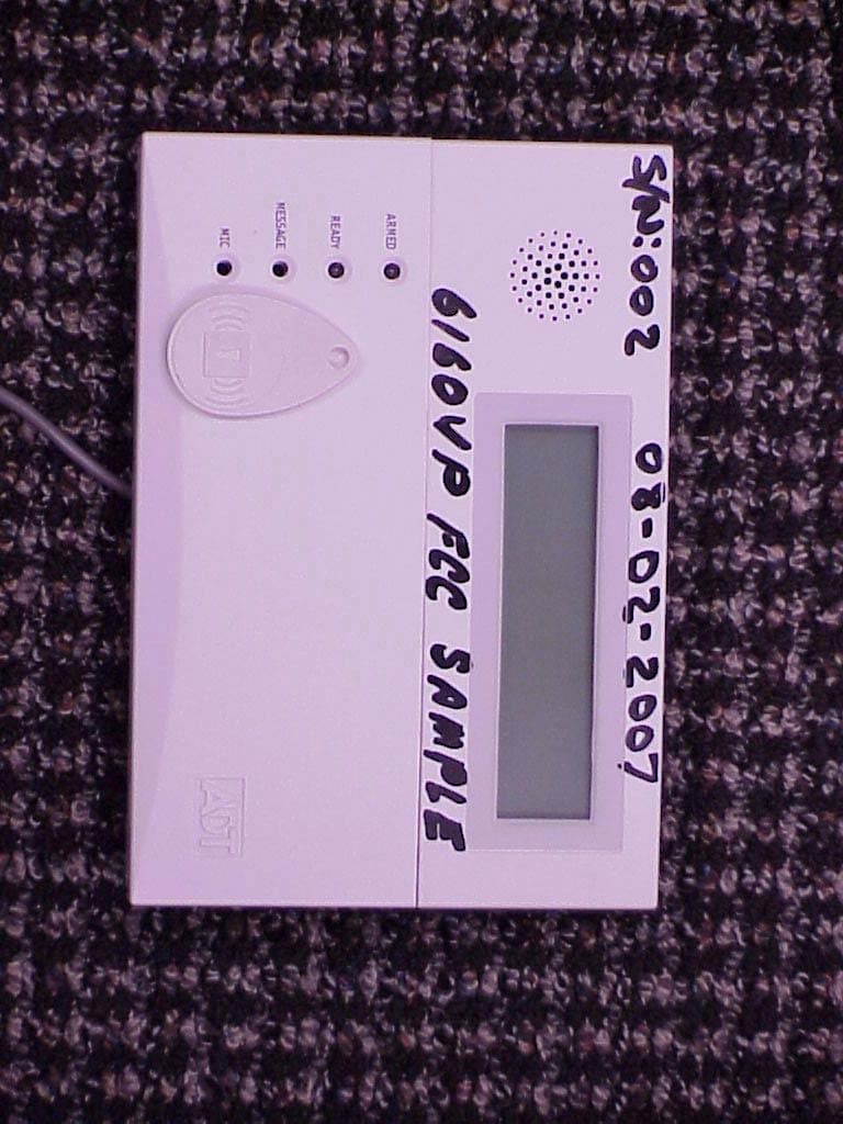
Click to zoom
Application Details
- Equipment Class
- DXX - Part 15 Low Power Communication Device Transmitter
- Date of Grant
- Aug 31, 2007
- Application Purpose
- Original Equipment
- Date of Application
- Aug 30, 2007
- Equipment Note
- Remote Touchpad with Prox Reader
- Frequency Range
- 13.56000000 - 13.56000000
- Company
- Ademco Inc.
- Country
- United States
Documents & Files
Document Text
Text extracted from the exhibit documents filed with the FCC. Open a document above to read the original.
Users Manual
PREK14804 6/07 Rev. A 6160VPADT 6160VPADT6160VPADT 6160VPADT Remote Touchpad with Prox Reader INSTALLATION and SETUP GUIDE GENERAL INFORMATION The 6160VPADT is an addressable remote Touchpad designed for use with ADT control panels. This Touchpad provides the following features: • Backlit Display • Programmable Function Keys • Built-in Sounder • Arm/Disarm via Prox Tag • Voice Chime • Voice Status • Message Center Notes: • When used with the Safewatch Pro/Security Manager 3000 control panels, address 16 must be assigned to the first Touchpad. Additional Touchpads must be assigned to addresses 17 – 23. Refer to Setting The Touchpad Options. • Touchpad keys are continuously backlit for convenience. • Permanent display backlighting is an option on some controls (refer to the control panel’s instructions for details). • Voice Chime should only be enabled when used with control panels that support the "chime by zone" mode (e.g., SAFEWATCH PRO/SECURITY MANAGER 3000). This mode must be enabled at the control panel. Refer to the control panel's installation and setup guide for information on how to program the chime mode. • Use only zone descriptors supported by this Touchpad. If using zone descriptors not supported by this Touchpad, you must turn voice status and voice chime off. Table 1 is a list of applicable zone descriptors and index entries. Refer to the control panel’s installation and setup guide for information about how to program zone descriptors. TOUCHPAD DISPLAYS AND LEDS The Touchpad provides a two-line alphanumeric display and custom zone descriptors. The following table identifies the Touchpad’s LEDs and associated functions: LED Function ARMED Lights red when the system is armed in any mode. READY Lights green when the system is "ready" to be armed. MESSAGE Flashes red when message waiting or lights (steady) when in record mode. PROGRAMMABLE FUNCTION KEYS The Touchpad's programmable function keys [A, B, C] are normally used for Touchpad panic functions, but they can be programmed for other special functions instead. If they are programmed for other special functions, the associated Touchpad key pairs still provide the respective panic alarm (if programmed). Refer to the control panel’s Installation & Setup Guide for details. Function Keys Equivalent Key Pairs A [1] and [*] B [*] and [#] C [3] and [#] D NONE • Function keys must be held down for at least 2 seconds to activate the programmed function. • If functions other than panics are assigned to the programmable function keys, programmed panics must be initiated by pressing the programmed key pair. FUNCTION KEY LABELS A set of adhesive-backed labels with some typical function symbols (i.e., fire, police, personal emergency, etc.) is provided. These labels can be placed on or next to the keys to identify each key's function for the end user (as determined by the capability and programming of the control panel; refer to the installation and setup guide for the control panel). 6160vADT-50-001-V0 MOUNTING RELEASE SNAPS (Remove case back by pushing up the 2 "snaps" along the keypad's bottom edge and pulling the case apart.) SIDE VIEW 1 2 3 4 5 6 7 8 9 0 # STAY BYPASS CHIME INSTANT AWAY CODE TEST OFF READY ARMED READY MIC MESSAGE RECORD VOLUME PLAY STATUS FUNCTIONVOICE A B C D WIRING AND INSTALLATION Touchpads can be surface mounted using drywall anchors or to a single- or double-gang electrical box. 1. Remove the case back by pushing in the two "snaps" along the Touchpad’s bottom edge and pulling the case apart. See diagram above. 2. Route wiring from the control panel through the opening in the case back. 3. Mount the case back to a wall or electrical box. Do not connect the ECP Data In or Data Out until directed to do so. If the Prox Reader detects the presence of ECP Data In and Out connections during address programming mode, it will exit to “normal” mode. The touchpad addresses being used for the touchpad and the Prox Reader must be enrolled in the control panel. - 2 - 4. Wire directly from the Touchpad’s terminal block to the terminal block on the control panel. (Refer to Wiring Table). Connect only the red and black Aux. Power connections at the control panel. Wiring Table Touchpad Control Panel Wire Color G Data In Green – – Aux Pwr (GND) Black + + Aux. Pwr (POS) Red Y Data Out Yellow 5. Re-attach the Touchpad to the case back. 6. Remove clear protective film from LCD display. SETTING THE TOUCHPAD OPTIONS The procedures that follow are used to set the Touchpad address, voice chime mode, and additional voice Touchpad mode. Setting the Touchpad Address When used with the Safewatch Pro/Security Manager 3000 control panels, address 16 must be assigned to the first Touchpad. Additional Touchpads must be set at 17 - 23 and must be enabled additionally in control programming (fields *190 - *196). The Touchpad may be set for address 00-30 or for non- addressable mode (31). The default Touchpad address is 31. For valid address settings for your Touchpad, refer to the control panel's Installation & Setup Guide. Notes: • If unable to enter the address mode, power down, power up, and try again. • If 10 seconds pass with no key entry, the Touchpad automatically exits the address mode. You must power down, power up, and start the address mode again. • The Touchpad will not enter the address mode if the control panel is in programming mode. 1. Apply power to the Touchpad. 2. Within 60 seconds of applying power to the Touchpad, press and hold down the [1] and [3] keys at the same time for 3 seconds. The current Touchpad address will be displayed. 3. Press "00". The current address is cleared. 4. Enter desired two-digit Touchpad address. 5. Press [✱] to accept the displayed address and enter the Voice Chime Mode. "VOICE CHIME" is displayed along with the selected mode "1" or "0". Setting The Voice Chime Mode Setting Voice Chime mode off does not effect the voice status or alarm annunciation. 1. Press [1] to set the Voice Chime mode on or pr…
Text truncated - open the document above for the full version.
Cover Letter(s)
EXHIBIT 1 CFS8DL6160VPADT / 573F-6160VPADT 6160VP FUNCTIONAL DESCRIPTION The 6160VPADT consists of a standard Honeywell / Ademco 6160V keypad and prox card reader board in the same plastic. It outputs the proprietary Honeywell / Ademco ECP data format to a Honeywell / Ademco alarm system control panel. This allows the 6160VPADT Keypad to arm / disarm the alarm panel conventionaly (with keystrokes) or with a 'prox card'.
ID Label/Location Info
EXHIBIT 8 LABEL INFORMATION CFS8DL6160VPADT / 573F-6160VPADT SECTION 2.1033 (c) and Part 15.21 SECTION 2.1033 (c) Label and label location - A photo showing the identification label clearly (you must be able to see the name and FCC ID number), and the location on the device. In lieu of a photo for this, you may submit a engineer’s drawing. Part 15.21 & RSS 210 Statement - for all intentional and unintentional radiators is also printed on the label. All devices shall bear the following statement in a conspicuous location on the device: “ This device complies with Part 15 of the FCC Rules and RSS 210 of Industry Canada . Operation is subject to the following two conditions: (1) this device may not cause harmful interference, and (2) this device must accept any interference received, including interference that may cause undesired operation. “ The Label shall also display the IC ID and a IC Model Number.
Internal Photos
EXHIBIT 4-3 PICTURES OF PCB IN PLASTIC CFS8DL6160VPADT / 573F-6160VPADT PAGE 1 OF 2 PAGE 2 OF 2
Internal Photos
EXHIBIT 4-4 PHOTOGRAPHS OF THE PCB’S CFS8DL6160VPADT / 573F-6160VPADT PAGE 1 OF 3 TOP OF THE PROX BOARD: BOTTOM OF THE PROX BOARD: . PAGE 2 OF 3 TOP OF THE KEYPAD BOARD: BOTTOM OF THE KEYPAD BOARD: PAGE 3 OF 3 TOP OF THE DISPLAY MODULE PCB: BOTTOM OF THE DISPLAY MODULE PCB:
Operational Description
EXHIBIT 2-1 CIRCUIT DESCRIPTION CFS8DL6160VPADT / 573F-6160VPADT 6160VPADT The 6160VPADT keypad contains several functions, such as keypad, panel interface, and LCD display, please refer to the Block Diagram ( EXHIBIT 2-2 ), and the Schematic ( EXHIBIT 2-3 ). The MICROPROCESSOR U3 of the main board controls all functions between the DISPLAY MODULE, KEYPAD KEYS, ALARM CONTROL PANEL. The 13.56 MHz card reader circuit board is a stand alown Prox card reader that outputs Honeywell / Ademco ECP proprietary data format directly to the ECP lines. The card reader is programmed to look like another keypad in the alarm panel system. In the presence of a valid prox card the card reader toggles the ARM / DISARM commands to the panel via the ECP Lines. The card reader functions as follows: Microprocessor U3 of the prox card controls al l card reader functions. YL1 is the system clock and the FDE for 13.56 MHz field. Q3 functions as a PA stage an d excites the antenna: ANT1 CR7, CR8 & Q2 function as a detector to demodulate the backscatter signal from the RFID Card. U6 acts as a level shifter for the demodulated signal so it can be processed by microprocessor U3. U 5 conditions the microprocessor data in and data out data lines to be compatible with the ECP line levels. The 6160VP meets all the requirements of a “Class B digital device” as well.
Operational Description
EXHIBIT 3-1 TIMING CALCULATION CFS8DL6160VPADT / 573F-6160VPADT A standard command message consists of the following: 1 mSec of CW followed by: 5 Bytes of ASK MANCHESTER READER DATA The reader data is sent at 423 KBS so therefore (1/423,000) X 5 X 8 = 9.45nSec Since the data is Manchester the transmitter is only on for 50% of the time so the TX ON TIME is: 4.725nSec This is followerd by another 1 mSec of CW and then another 4.17 mSec of CW durring which time the TAG Backscatters it's data back to the reader. This is a total of: 1mSec + 9.45nSec + 1mSec + 4.17mSec = 6.17001 mSec. A propriety command message consists of the following: 1 mSec of CW followed by: 1 Byte of 423 KBS (1/423,000) X 5 = 1.89nSec Since the data is Manchester the transmitter is only on for 50% of the time so the TX ON TIME is: 0.945nSec. This is followerd by 3.0mSec of CW and then another 1.74mSec of CW durring which time the TAG Backscatters it's data back to the reader. The reader then processes the information and sends another 5 Byte message to the TAG so... (1/423,000) X 5 X 8 = 9.45nSec Since the data is Manchester the transmitter is only on for 50% of the time so the TX ON TIME is: 4.725nSec This is followerd by 3.0mSec of CW and then another 3.47mSec of CW durring which time the TAG Backscatters it's data back to the reader. This is a total of: 1mSec + 0.945nSec + 3.0mSec + 1.74mSec + 4.725nSec + 3.0mSec +3.47mSec = 12.21001mSec
Operational Description
EXHIBIT 3-2 PROX CARD READER TRANSMISSION CFS8DL6160VPADT / 573F-6160VP ADT
Test Report
EXHIBIT 5-1 CFS8DL6160VPADT / 573F-6160VPADT Report of Measurements. Measurements for Conducted Emissions and Fundamental Radiator were made in accordance with the procedures and reporting requirements at: Honeywell’s QA Measurement Facility and Honeywell's OATS ( FCC No: 152762 & IC No:573F-1 ) both of which are located at: 2 Corporate Center Drive, Melville, NY 11747. Measurements for the Intentional and Unintentional Radiator (30 MHz through 1GHz portions) were made in accordance with the procedures and reporting requirements by: Underwriters Laboratories Inc. ('UL') 1285 Walt Whitman Road, Melville, NY 11747. REPORT OF MEASUREMENTS ( This EXHIBIT ) EXHIBIT 5-1 PICTURES OF THE TEST SET UP are found in EXHIBIT 5-2 RADIATED EMISSIONS are recorded in EXHIBIT 5-3 BANDWIDTH MASK is recorded in EXHIBIT 5-4 UNINTENTIONAL RADIATOR is recorded in EXHIBIT 5-5 CONDUCTED EMISSIONS are recorded in EXHIBIT 5-6 TEST EQUIPMENT USED is recorded in EXHIBIT 6
Test Report
EXHIBIT 5-3 INTENTIONAL RADIATOR CFS8DL6160VPADT / 573F-6160VPADT 47 CFR §15.209 Radiated Emission Limits; General Requirements. (a) Except as provided elsewhere in this subpart, the emissions from an intentional radiator shall not exceed the field strength levels specified in the following table: --------------------------------------------------------------------- Measurement Frequency (MHz) Field strength distance (microvolts/meter) (meters) -------------------------------------------------------------------- 0.009-0.490................. 2400/F(kHz) 300 0.490-1.705................. 24000/F(kHz) 30 1.705-30.0.................. 30 30 30-88....................... 100** 3 88-216...................... 150** 3 216-960..................... 200** 3 Above 960................... 500 3 --------------------------------------------------------------- Honeywell International,Inc. 6160 VPADT X Axis Keypad with Prox Reader intentional radiated Tested By: MA Limit: FCC Part 15 Subpart C 15.209 Horizontal 30 - 200MHz ------------------------------------------------------- Test Meter Gain/Loss Transducer Level dB No. Frequency Reading Factor Factor [uVolts/ [MHz] [dB(uV)] [dB] [dB] meter] Limit 4 773.1821 10.44 pk 1.4 21.5 33.34 46 Azimuth:299 Height:200 Horz Margin [dB] -12.66 5 820.6805 8.88 pk 1.6 22.4 32.88 46 Azimuth:299 Height:101 Horz Margin [dB] -13.12 Vertical 30 - 200MHz --------------------------------------------------------- 1 78.7658 30.06 pk -.1 7.1 37.06 40 Azimuth:183 Height:101 Vert Margin [dB] -2.94 2 63.002 22.53 pk -.2 6.0 28.33 40 Azimuth:293 Height:101 Vert Margin [dB] -11.67 3 54.2695 20.52 pk -.1 8.1 28.52 40 Azimuth:74 Height:101 Vert Margin [dB] -11.48 6 819.6131 7.93 pk 1.5 23.1 32.53 46 Azimuth:340 Height:200 Vert Margin [dB] -13.47 NOTE: "+" - Indicates an emission level in excess of the applicable limit (s). pk - Peak detector, qp - Quasi-Peak detector, av - Average detector, avlg - denotes average log detection, ave - denotes average detection, tm - Trace Math Result Page 1 EXHIBIT 5-3 ( CONT.) FUNDAMENTAL CFS8DL6160VPADT / 573F-6160VPADT FCC Part 15.225 Operation within the band 13.110-14.010 MHz. IC RSS 210 A2.6 Operation within the band 13.110-14.010 MH z NOTE: RSS 210.A2.6 and Part 15.225(a) are now harmonized: "The field strength of any emission shall " The field strength of any emission shall not exceed the following limits:" not exceed the following limits: " 15.848 millivolts/meter at 30 m < THIS IS THE SAME VALUE > 15,848 microvolts/meter at 30 m In accordance with 15.31, a correction of 40 db per decade of distance must be applied to the 15.225(a) readings for use on a 3 Meter Site: Correction Factor = 40 log (distance 1/ distance 2) = 40 log (30/3) = 40 dB Correction Factor = 10^(40 dB/20) = 100 X 3 Meter limit = 15,848 microvolts/meter X 100 = 1,584,800. uV/M = 1,584.8 mV/M The center of the UUT & sense loop antenna must remain at a constant 1 meter height during the test. Transmit Frequency:13.5603 MHz2ed Harmonic Frequency:27.1206 MHz CABLE "A"& "B", Cable/Amp Factor (dB):1.2dbCABLE "A"& "B", Cable/Amp Factor (dB):1.3db Antenna Factor (dB):36.15Antenna Factor (dB):26.00 WORST READINGS: Unit Position:OBLQUnit Position:OBLQ Loop Position:0 degLoop Position:0 DEG Reading (mV/M): 1.7Reading (dB uV):38 LIMIT:1,584.80LIMIT:40 [(Meter reading + Cable/Amp factor + Antenna factor) / 20 )] Conv. Reading = 10 ObservedUnitLoopDBuV:db:db:mV/M:mV/M: Freq:Position:Position:S/A Reading:Cable Loss:AF:FS:LIMIT: 13.5603 MHzHORS0 DEG20.491.236.150.81,584.8 13.5603 MHzVERT0 DEG26.291.236.151.51,584.8 13.5603 MHzOBLQ0 DEG27.391.236.151.71,584.8 13.5603 MHzHORS90 DEG21.191.236.150.81,584.8 13.5603 MHzVERT90 DEG24.591.236.151.31,584.8 13.5603 MHzOBLQ90 DEG22.891.236.151.01,584.8 13.5603 MHzHORS45 DEG20.611.236.150.81,584.8 13.5603 MHzVERT45 DEG22.591.236.151.01,584.8 13.5603 MHzOBLQ30 DEG24.991.236.151.31,584.8
Test Report
EXHIBIT 5-5 UNINTENTIONAL RADIATOR CFS8DL6160VPADT / 573F-6160VPADT 47 CFR §15.109 Radiated Emission Limits. (a) The field strength of radiated emissions from unintentional radiators at a distance of 3 meters shall not exceed the following values: ---------------------------------------------------------------------------- Field Strength Frequency of emission (MHz) (uV/Meter) --------------------------------------------------------------------------- 30-88....................................................... 100 88-216..................................................... 150 216-960................................................... 200 Above 960............................................... 500 --------------------------------------------------------------------------- (c) In the emission tables above, the tighter limit applies at the band edges. Sections 15.33 and 15.35 which specify the frequency range over which radiated emissions are to be measured and the detector functions and other measurement standards apply. Honeywell International,Inc. 6160 VPADT X Axis Keypad with Prox Reader Tested By: MA Limit: FCC Part 15 Class B Horizontal 30 - 200MHz ------------------------------------------------------- No. Frequency Reading Factor Factor dB[uVolts/meter] [MHz] [dB(uV)] [dB] [dB] 5 189.9066 19.05 pk .2 15.5 34.75 43.5 Azimuth:15 Height:101 Horz Margin [dB] -8.75 6 76.2975 18.66 pk .1 15.1 33.86 43.5 Azimuth:344 Height:399 Horz Margin [dB] -9.64 Vertical 30 - 200MHz --------------------------------------------------------- 1 78.7658 30.46 pk -.1 7.1 37.46 40 Azimuth:329 Height:101 Vert Margin [dB] -2.54 2 63.0020 24.84 pk -.2 6.0 30.64 40 Azimuth:219 Height:101 Vert Margin [dB] -9.36 3 67.7652 23.19 pk -.1 5.5 28.59 40 Azimuth:37 Height:101 Vert Margin [dB] -11.41 4 162.8019 16.16 pk .1 15.9 32.16 43.5 Azimuth:329 Height:101 Vert Margin [dB] -11.34 1 78.7500 31.36 qp -.1 7.1 38.36 40 Azimuth: 249 Height:109 Vert Margin [dB]: -1.64 NOTE: "+" - Indicates an emission level in excess of the applicable limit (s). pk - Peak detector, qp - Quasi-Peak detector, av - Average detector,avlg - denotes average log detection, ave - denotes average detection, tm - Trace Math Result
Test Report
EXHIBIT 5-6 Conducted Limits CFS8DL6160VPADT / 573F-6160VPADT 15.207 Conducted Limits. (a)... for an intentional radiator that is designed to be connected to the public utility (AC) power line, the radio frequency voltage that is conducted back onto the AC power line on any frequency or frequencies, within the band 150 kHz to 30 MHz, shall not exceed the limits in the following table, as measured using a 50 μH/50 ohms line impedance stabilization network (LISN). Compliance with the provisions of this paragraph shall be based on the measurement of the radio frequency voltage between each power line and ground at the power terminal. The lower limit applies at the boundary between the frequency ranges. (c) Measurements to demonstrate compliance with the conducted limits are not required for devices which only employ battery power for operation and which do not operate from the AC power lines or contain provisions for operation while connected to the AC power lines. Devices that include, or make provisions for, the use of battery chargers which permit operating while charging, AC adapters or battery eliminators or that connect to the AC power lines indirectly, obtaining their power through another device which is connected to the AC power lines, shall be tested to demonstrate compliance with the conducted limits. ---------------------Conducted limit (dBμV) ---------------------------- Frequency of emission (MHz) Quasi-peak Average 0.15-0.5................................................. 66 to 56*.......... 56 to 46* 0.5-5........................................................... 56..................... 46 5-30............................................................ 60..................... 50 -------------------------------------------------------------------------------- • Decreases with the logarithm of the frequency. • PICTURE OF THE TEST SETUP: TEST RESULTS: Honeywell Conducted Emissions - 150 kHz - 30 MHz Line 1 100.0K1.0M10.0M100.0M Frequency 0 10.0 20.0 30.0 40.0 50.0 60.0 70.0 80.0 90.0 100.0 Amplitude (dBμV) Equipment ID: 6160VPADT10:33:13 AM, Tuesday, August 07, 2007 C:\tile\Honeywell\PRE6160VPADT.TIL Operator: shao FCC B AVG FCC B QP Line 1 quasi-peak average CONTINUED ON PAGE 2 TEST RESULTS CONT. Honeywell Conducted Emissions - 150 kHz - 30 MHz Line 2 100.0K1.0M10.0M100.0M Frequency -10.0 0 10.0 20.0 30.0 40.0 50.0 60.0 70.0 80.0 Amplitude (dBμV) Equipment ID: 6160VPADT10:31:29 AM, Tuesday, August 07, 2007 C:\tile\Honeywell\PRE6160VPADT.TIL Operator: shao FCC B AVG FCC B QP Line 2 quasi peak average Honeywell Security QP measurements on highest points QP Table Operator: shao Equipment ID: 6160VPADT C:\tile\Honeywell\PRE6160VPADT.TIL 10:33:13 AM, Tuesday, August 07, 2007 Frequency CISPR B L1 QP margin L2 QP margin CISPR B L1 AVG margin L2 AVG margin MHz QP lim (dBμV) L1(±dB) (dBμV) L2(±dB) AVG lim (dBμV) L1(±dB) (dBμV) L2(±dB) 148914 NAN 52.310 NAN NAN NAN NAN 32.730 NAN NAN NAN 150000 66.000 NAN NAN NAN NAN 56.000 NAN NAN NAN NAN 150457 65.987 NAN NAN 52.890 13.097 55.975 NAN NAN 32.100 23.875 271841 62.519 NAN NAN 47.880 14.639 51.062 NAN NAN 17.420 33.642 276385 62.389 NAN NAN 47.430 14.959 50.924 NAN NAN 16.320 34.604 276728 62.379 NAN NAN 47.280 15.099 50.914 NAN NAN 16.300 34.614 278145 62.339 NAN NAN 47.420 14.919 50.871 NAN NAN 16.290 34.581 279298 62.306 NAN NAN 47.070 15.236 50.837 NAN NAN 16.310 34.527 280679 62.266 NAN NAN 46.320 15.946 50.796 NAN NAN 16.180 34.616 281264 62.250 NAN NAN 46.910 15.340 50.778 NAN NAN 16.243 34.535 282736 62.208 NAN NAN 46.590 15.618 50.735 NAN NAN 16.260 34.475 283629 62.182 NAN NAN 46.500 15.682 50.709 NAN NAN 15.370 35.339 500000 56.000 NAN NAN NAN NAN 46.000 NAN NAN NAN NAN 5e+006 56.000 NAN NAN NAN NAN 46.000 NAN NAN NAN NAN 5e+006 56.000 NAN NAN NAN NAN 46.000 NAN NAN NAN NAN 1.3554e+007 60.000 50.890 9.110 NAN NAN 50.000 29.643 20.357 NAN NAN 3e+007 60.000 NAN NAN NAN NAN 50.000 NAN NAN NAN NAN 6160VP S/N: 002 6160VP & 6160VPADT CFS8DL6160VPADT & IC: 573F-6160VPADT
Test Report
EXHIBIT 6 TEST EQUIPMENT USED CFS8DL6160VPADT / 573F-6160VPADT Section 15.231 and ANSI C63.4 Section 15.231 This is a list of all test equipment used. Test Equipment list for Honeywell OATS: Equipment Mfg Model Cal Date Cal Due Loop Antenna Electro-Metrics ALR-25M 08/03/07 08/03/08 Spectrum Analyzer TEKTRONIX 2784 10/16/06 10/16/07 If you need any additional information from Honeywell please contact: Greg Barbato RF Engineer (Acting for Ken Addy) Phone (Direct): (516) 577-5863 Email: [email protected] Test Equipment list for Honeywell Conducted Emissions: Equipment Mfg Model Cal Date Cal Due Spectrum Analyzer Agilent HP8593E 2/16/07 2/16/08 Surge Suppressor Agilent HP11947A 5/02/07 5/02/08 LISN Com-Power LI-115 2/13/07 2/13/08 If you need any additional information from Honeywell please contact: Greg Barbato RF Engineer (Acting for Ken Addy) Phone (Direct): (516) 577-5863 Email: [email protected] Test Equipment list for Underwriters Laboratories Inc.: Equipment Mfg Model Cal Date Cal Due EMI Receiver Rohde &Schwarz ESIB26 11/14/06 11/14/07 Biconical Antenna Schaffner VBA6106A 2/28/07 2/28/08 Log Periodic Antenna Schaffner UPA6109 2/26/07 2/26/08 If you need any additional information from UL please contact: Michael Antola Project Engineer Underwriters Laboratories International EMC and NEBS Services Phone (Direct): (631) 546-3053 Email: [email protected]
Test Report
EXHIBIT 5-4 BANDWIDTH MASK CFS8DL6160VPADT / 573F-6160VPADT BW Mask of the fundamental shall be within 14 KHz of the center frequency. The Initial Resolution bandwidth <1% of the frequency used within the band: 13.410 – 13.553MHz The 99% point will be represented by the 20 db down points between a 1 MHz Resolution Bandwidth and the minimum allowable resolution bandwidth which is 1KHz.
Test Setup Photos
EXHIBIT 5-2 PICTURES OF THE TEST SITE CFS8DL6160VPADT / 573F-6160VPADT CONDUCTED EMISSIONS AT HONEYWELL’S QA MEASUREMENT FACILITY AT 2 CORPORATE CENTER DRIVE, MELVILLE, NY 11747.: INTENTIONAL RADIATOR ( 13.56 MHz FUNDAMENTAL ) AT HONEYWELL’S OATS MEASUREMENT FACILITY AT 2 CORPORATE CENTER DRIVE, MELVILLE, NY 11747.: LOOP PARALLEL UUT HORIZONTAL UUT VERTICAL UUT OBLIQUE LOOP AT 90 DEGREES UUT HORIZONTAL UUT VERTICAL UUT OBLIQUE LOOP BETWEEN 0 AND 90 DEGREES UUT HORIZONTAL UUT VERTICAL UUT OBLIQUE UNINTENTIONAL AND INTENTIONAL RADIATOR ( 30 MHz TO 1 GHz PORTIONS ) AT UL’S 10 METER CHAMBER SITE:
Contact Information
Applicant
Christian Fouth(Sr. Wireless Certification Engineer)
Test Firm
Honeywell International Inc.Mark Schmidt
Technical Specifications
| # | Rule Parts | Frequency Range | Power Output |
|---|---|---|---|
| 1 | 15C | 13.56 MHz - 13.56 MHz | - |
Other Applications from Ademco Inc.

CFS8DL5800MINIV
Jan 28, 2026Wireless Alarm Transmitter
Equipment Class
DXX - Part 15 Low Power Communication Device Transmitter
CFS8DLWTS800
Jan 12, 2026Wireless Alarm Transmitter
Equipment Class
DTS - Digital Transmission SystemCFS8DLCAMWEWI1
Jul 25, 2024VX5 HD Indoor Camera
Equipment Class
DTS - Digital Transmission System
CFS8DLCAMWEWO1
Sep 17, 2023VX3 HD Outdoor Camera
Equipment Class
NII - Unlicensed National Information Infrastructure TX
CFS8DLLMD500A
Jul 20, 2023Wireless door/window contact
Equipment Class
DTS - Digital Transmission System