CFS8DL6162RFKeypad Transceiver
Ademco Inc.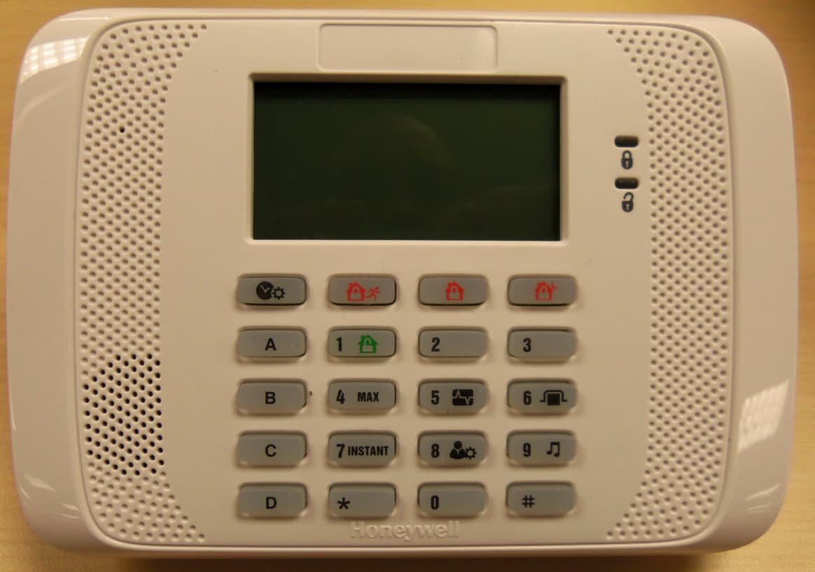
Click to zoom
Application Details
- Equipment Class
- DSR - Part 15 Remote Control/Security Device Transceiver
- Date of Grant
- May 07, 2013
- Application Purpose
- Original Equipment
- Date of Application
- May 07, 2013
- Equipment Note
- Keypad Transceiver
- Frequency Range
- 344.94000000 - 344.94000000
- Company
- Ademco Inc.
- Country
- United States
Documents & Files
Document Text
Text extracted from the exhibit documents filed with the FCC. Open a document above to read the original.
Users Manual
ADEMCO 6162RF Keypad / Transceiver – Installation and Setup Guide Alphanumeric Addressable Keypad/Transceivers for use with Honeywell Control Panels; incorporates functions of a High RF Receiver and a 5800 Transmitter module. = READY to Arm = NOT READY to Arm = System ARMED = System NOT ARMED Arming Keys 6162: 4-Line Alpha Display Custom Zone Designators 6162rf-KEYPAD-LBLD-V0-032713 Programmable Function Keys Sounder Wall Surface Control Panel Terminal Strip AU X DATA IN DATA OUT AUX 2 1 Y G To Control Panel Terminal Strip Optional Front Cover Securing Screw (Required in European Installations) Install Four (4) Mounting Screws Control Panel 1. OPEN Keypad Front Cover 2. WIRE 3. MOUNT • Connect only one wire per terminal. • For Daisy-Chain Configurations, use wire splicing so only one wire is connected to each terminal. • Mount on drywall, or in a single or double-gang electrical box. 6162RF-installation-3-21-13 Black (Gnd) Red (+12vdc) Green (Data To Control) Yellow (Data From Control) To activate Function keys, press and hold key for at least 2 seconds; key pairs are activated immediately. Table 1 – Programmable Function Keys A or and B or and C or and D Note: See the control's instructions for details on programming the Function keys for panic alarms or other special functions (i.e., macros). • Supports wireless key transmitters (e.g., 5834-4) and bi-directional transmitters (e.g.; 5804BD, 5828/5828V). • Supports wireless keys with high- security (encryption) capability (e.g.; 5834-4). • Provides a nominal range of 200 feet for RF transmitters (some transmitters have a shorter range). • Supports RF jam detection. Table 3 – Icon Descriptions ICON DESCRIPTION TEST SYSTEM BYPASS ZONES ASSIGN CODES CHIME MODE ARM MAXIMUM ARM INSTANT ARM AWAY ARM NIGHT STAY DISARM ARM STAY SETTINGS Table 2 – Settings Key Settings KeyResult Press Displays Settings Menu*: 1 Set Time/Date 2 View Event Log 3 Reboot Keypad 4 Set User Code** * Follow instructions in the User Guide for these options; selecting option 3 reboots the 6162 keypad. ** Set User Code option available only with the following Control Panels: VISTA-10P Rev 4.16, VISTA-15P Rev 9.16, VISTA- 20P Rev 9.16 and VISTA-21iP Rev 3.16. - 2 - APPLICATION GUIDELINES FOR THE 6162RF Table 4 – Application Guidelines If... And... Then... This is the only transceiver on the system, You want to use both the receiver and transmitter function on a single-partition system, • Set the keypad to a device address assigned to the desired partition.* • Enable the receiver. • Program a system House ID in the control panel (this will enable the transmitter function).** • Set the wireless devices that will communicate with this 6162RF to the same system House ID. There is another receiver or transceiver on the system, You want to use only the transmitter function on a second partition, • Set the keypad to a device address assigned to the desired partition.* • Disable the receiver. • Program a DIFFERENT House ID in the 6162RF than is programmed in the control panel.*/ ** • Set the wireless devices that will communicate with this 6162RF to the same House ID as the 6162RF. You want to use only the transmitter function on a single- partition system, • Set the keypad to a device address assigned to the Partition 1. • Disable the receiver. • Program a House ID in the 6162RF that matches the system House ID programmed in the control panel.* • Set the wireless devices that will communicate with this 6162RF to the same House ID. Notes: * On VISTA-40 panels and above, wireless keypads (e.g., 5828) can only be used on a single partition. This partition is programmed in field 1*48, and must match the partition assigned to the 6162RF. Wireless keys can be used on more than one partition, using a House ID programmed in the 6162RF and the devices. In this case, the wireless keys must be assigned to the same partition as the 6162RF. ** On VISTA-20P panels, the 6162RF will use the House ID programmed in the panel for the partition to which it is assigned. Wireless keypads can only be used on Partition 1. 4. PROGRAM Refer to the following procedure to program the 6162RF: Table 5 – 6162RF Programming STEP DESCRIPTION DISPLAY CHOICES 1. Enter Programming Mode: Within 60 seconds of power up, press and hold down the and keys at the same time for 3 seconds. 2. Keypad Address. The keypad address appears (Default = 16). Enter a two-digit keypad address. Press the key to continue. Notes: – Refer to the control panel’s installation instructions for the acceptable keypad addresses. CON ADDR = 16 00-31 3. Receiver Enable. Enter [1] to enable, or [0] to disable the receiver. Press to continue. RECEIVER ON [0= OFF] 1 = ON 0 = OFF 4. Receiver Address. If the receiver is enabled, enter the two-digit receiver address. (00-30). Note: Refer to the control panel’s installation instructions for the acceptable receiver addresses. Press to continue. REC ADDR = 00 00-30 5. User Code. Enter a valid four-digit user code to enable single button arming keys. The user code must be programmed in the control. Press to continue. USER CODE : **** 0000-9999 - 3 - Table 5 – 6162RF Programming (continued) STEP DESCRIPTIONDISPLAY CHOICES 6. House ID. This prompt will only appear if the receiver is disabled. If the receiver is enabled the 6162RF will use the House ID programmed in the panel. Refer to Application Guidelines section when selecting a House ID. To program a House ID: Enter 01-31 To disable the transmitter: Enter 00 Note: Each device that will receive status from the 6162RF must be set to the same House ID as the 6162RF (refer to Application Guidelines section). Press to continue. HOUSE ID = XX 01-31 00 = Disable Transmitter 7. Enable High Security Mode. Enter [1] to select High Security Mode. Note: If the High Security mode is enabled, the 6162RF will only recognize encrypted devices. If the High Security mode is disabled, the 6162RF will process commands from both encrypted and non-encrypted devices. Press to …
Text truncated - open the document above for the full version.
External Photos
EXHIBIT 4-1 CFS8DL6162RF / 573F-6162RF PHOTOGRAPHS OF DEVICE
ID Label/Location Info
EXHIBIT 8 CFS8DL6162RF / 573F‐6162RF DEVICE LABEL
Internal Photos
EXHIBIT 4-2 CFS8DL6162RF / 573F-6162RF INTERNAL PHOTOGRAPHS OF DEVICE PCB IN PLASTIC TOP OF PCB BOTTOM OF PCB
Test Report
EXHIBIT 5-1 CFS8DL6162RF / 573F-6162RF Report of Measurements . Measurements for the Intentional Radiator,and OBW were made in accordance with the procedures and reporting requirements at: Honeywell's OATS ( FCC No: 152762 & IC No:573F-1 ) which is located at: 2 Corporate Center Drive, Melville, NY 11747. Measurements were made in accordance with the procedure and reporting requirements of ANSI C63.4-2003. The Test Set-Up (C63.4 section 10.1.3) is shown in EXHIBIT 5-2; "Test Setup Photos". The sequence of testing (C63.4 section 10.1.7) for radiated emissions is as follows: A preliminary scan was conducted with the receiver antenna close to the EUT in order to identify the emission characteristics of the EUT (C63.4 section 8.3.1.1). The antenna and EUT were then placed at the proper separation ( 3 Meters) with the EUT positioned at 80 cm on a non-conducting turntable. The EUT was rotated on the turntable to maximize the received signal strength, then the receiver antenna height was varied between one (1) and four (4) Meters to further maximize the received reading. Thereafter, the device was again rotated to a peak output position and the antenna height wa s re-adjusted for maximum received signal. This procedure was re-iterated until there was no further increase in signal level. This procedure was performed with the EUT rotating in three orthogonal planes (C63.4 section 13.1.4.1) to generate a final maximum reading which is recorded on the radiated emissions result sheet. Similar measurements were made on the receiver to ensure compliance as an unintentional radiator. Note, The Spectrum Analyzer resolution bandwidths set as follows; (Video Bandwidth is always set 3X greater than RBW) For occupied bandwidth measurements, RBW = 30KHz and VBW = 100KHz. For radiated emissions below 1 GHz, the RBW = 100kHz. Detector function set to peak. For radiated emissions above 1 GHz, the RBW = 1MHz. Detector function set to peak. TRANSMITTER RADIATED EMISSIONS are recorded in "EXHIBIT 5-3". OCCUPIED BANDWIDTH is recorded in "EXHIBIT 5-4". TEST EQUIPMENT ( per C63.4 section 10.1.4) is recorded in "EXHIBIT 6".
Test Report
EXHIBIT 5-3 CFS8DL6162RF / 573F-6162RF HONEYWELL SECURITY & CUSTOM ELECTRONICS REV 08-21-2012-L 2 Corporate Center Drive Melville, NY 11747 EXHIBIT 5- 3 FCC ID:CFS8DL6162RF Date : 30-Jan 2013 Tested by: Greg Barbato Approved by: S. A. Test Sample (model): 6162RF Test method: ANSI C63.4 - 2003 Test specification: FCC Part 15, Sub-part C and RSS 210 , Issue 8 Notes: (1) Fo: 344.94 PRESCAN: (2) Detector = Peak SENSE / UUT: EL (cm): AZ (deg): Meter Reading (dB uV): (3) Frequency range scanned to 4 GHz. V/V 152.5 0.0 74.90 ( Emissions not reported were more than 20dB below the specified unit ). H/V 237.4 0.0 75.30 [(Meter reading + Cable/Amp factor + Antenna factor) / 20 )] V/H 100.0 81.0 78.49 (4) Conv. Reading = 10 H/H 100.0 81.0 81.68 (5) Corr. Reading = Conv. Reading X Duty Cycle V/O 138.6 179.0 79.43 (6) Six Highest Emissions Recorded H/O 243.0 179.4 79.47 Freq. (MHz): Sense Antenna Polarity (V/H): THE ORENTATION OF THE UUT (V,H,O,): Meter Reading (dB uV): Cable/Amp Factor (dB): Antenna Factor (dB/m): Conv. Reading (uV/M): Duty Cycle (%): Corr. Reading (uV/M): Limit @ 3M (uV/M): 344.94 H H 74.90 2.5 15.91 46,291.4 15.0% 6943.7 7,289 689.88 H H 32.56 3.7 21.12 741.3 15.0% 111.2 729 1034.82 H H 20.39 4.7 24.65 306.9 15.0% 46.0 500 1379.76 H H 23.98 5.6 27.53 717.8 15.0% 107.7 500 1724.70 H H 20.45 6.3 30.10 692.6 15.0% 103.9 729 2069.64 H H 21.74 7.3 31.04 1,003.5 15.0% 150.5 729 2414.58 H H 21.21 8.1 31.71 1,119.4 15.0% 167.9 729 2759.52 H H 22.67 8.6 32.29 1,508.3 15.0% 226.3 500 3104.46 H H 20.44 9.1 32.81 1,312.2 15.0% 196.8 729 3449.40 H H 21.78 10.0 34.46 2,044.1 15.0% 306.6 729 4000 LAST CAL 10 JUL 12 CABLE D LAST CAL 27-JUN-12 BICONILOG S/N:00020971
Test Report
EXHIBIT 5-4 CFS8DL6162RF / 573F-6162RF OCCUPIED BANDWIDTH (174.4 KHz)
Test Report
EXHIBIT 6 TEST EQUIPMENT USED Part 15.231, ANSI C63.4 , RSS 210 This is a list of all test equipment used. Test Equipment list for Honeywell OATS & Conducted Line: Equipment Mfg Model Cal Date Cal Due Spectrum Analyzer Rohde & Schwarz FSEA20 10/15/12 10/15/13 Antenna ‘B iconilog’ ETS Lindgren 3149 08/ 25/12 08/25/13 NOTE: THIS ANTENNA WAS CALIBRATED DOWN TO 26 MHz. PER OUR REQUEST. Surge Suppressor Agilent (HP) HP11947A 05/09/12 05/09/13 LISN Com -Power LI-115 10/19/12 10/19/13 PLEASE SEE PAGE 2-5 FOR TEST EQUIPMENT TRACEABILITY If you need any additional information from Honeywell please contact: Greg Barbato RF Engineer (Acting for Ken Eskildsen) Phone (Direct): (516) 577-5863 Email: [email protected] :!',,,,,,,.,rt,,,,,,t,,,,,,t,tt,,t,';t,,tt'.'.,,,.,.t;.1 .,,:,,,,tt,,,, Issue Date: 10/15!2A12 P.erfarmed,fui GENERAL CALIRRANON. INC. 2 MARS COURT BOONTON,NJ O7OO5 EquipmurttrU&datian;,. ..;,':, 1,,1,,,.,,..r1r,,1r,1'r Job No.: 018674 Manufacturer: R&S Description: Department: Temp./RH: Cal. Interval: Cal Date: General Calibration, Inc. 2 Mars Court, Boonton, New Jersey 07005 Phone (973) 299-2950 Fax (973) 299-0595 MR-22292 MR59O 00t464 SPECTRUM ANALYZER ALARMNET 22.0 C I 51.0o/o 12 MONTHS 10t15t2012 L*n':"AfgaHbil.'h 0f1:1i'',,,'1,,,,,:,,,,,, HONEYWELL SECURTry (001464) 2 CORPORATE CENTER DRIVE MELVILLE,NY I1747 hd.4i.',,,-O ti"..,.,t'.t,tt' Asset Tag No.: Model Number: Serial Number: Inspected By: Job Title: Calibration Result: Cal. Due Date: . .. :.tL::-::..:.. ..., s294448 10503 FSEA20 oB:riss MRI METROLOGIST PASSED t0t15t2013 Procedure#GCP;,, RSFSEA20 Calibration Notes: Condition: Found In Tolerance and Left In Tolerance Standards Used To Cailbrste nquipmentt, ,,.i . . , , Company LD. Description GENERAL CALIBRATION 1031 SYNTHESIZED SWEEPER, 26GHZ GENERAL CALIBRATION 1124 FUNCTION GENERATOR GENERAL CALIBRATION 2OO MEASURING RECEIVER GENERAL CALIBRATION 332 FREQUENCY COUNTER GENERAL CALIBRATION 403 ATTENUATOR GENERAL CALIBRATION 432 CALIBRATION KIT TYPE N 5O-OHMS GENERAL CALIBRATION 434 POWER SPLITTER GENERAL CALIBT{ATION 51I DIGITAL MULTIMETER GHNERAL CALIBRATION 518 POWER SENSOR GENERAL CALIBRATION 588 ATTENUAI-OR Seiial N,umber 30504021 8l 2847 1.11791 3+38A05277 ccN200l 001 26 219-05771 254t400233 11124 2201 404803 us37292728 2522440468 Qal; Due Date 04/12t2013 0513112013 08/08/20 l 3 05/21/2013 08/15/2013 t0/29/2012 t0/11/20t3 0410412013 06t2212013 07 t1812013 fhis is to certify that General Calibration, lnc. is A2LA accreoited and that its calibration system is in compliance with ISO/IECl7025-2O05,ANSI NCSL2540-1, ANSI NCSL Z540-3.andISo9001:2008.TheteSt|imitSstatedintherepurtcorrespondtotheManufacturercalibrationandpublishedspecications Ca|ibrationofstandards;re1.erencestandardsandintermediatcstandardsinthiscalibratronhavebeencheckedandcalibrated traceabletotheNationalinstituteofStandardsandTechnolo1..y,AnyaccreditedcalibrationunderourA2LAscopeofaccredit the calibration certificate. tfthe certitlcate includes any unacoredited items cahbrated, they are clearly marked as unaccredited calibration. Rcst Uncertainties represent expanded uncertainties expressed at approximately the 95% confidence level using a coverage factor ofk:2. The results documented in this certificate relate only to the item(s) calibrated or tested. Approved By ,ril'.;..v;'.-...,.,y'; .,* .. /y'1.:/,-a..- ..r- /. . - General Calibration, Inc. - Q. A. Manager Pagelofl l ilil rilli itltlil # gt lFcnE6flf6l '"J:TilT"',ii8;:;l SNffS.LINDCREIU- Operating Range: 80 MHz - 6 GHz Instrument Type: Biconilog (Type 5) Date Code: Alternate lD: 11242 Customer: HONEYWELL (NY) 26 - 1000 MHz, +/-0.9 dB; 1000 - 2000 MHz, +f 0.8 dB: 2000 - 6000 MHz. +t-1 .2 dB 26 - 1000 MHz, +/-0.9 dB; 1000 - 2000 MHz, +/-0.8 dB; 2000 - 6000 MHz. +/-1 .3 dB 26 - '1 000 MHz, +f 1 .0 dB; 1 000 - 2000 MHz, +l-1 .4 dB:2000 - 6000 MHz, +/-2.3 dB Condition of Instrument Upon Receipt: In Tolerance to Internal Qualitv Standards On Release: In Tolerance to Internal Qualitv Standards Cert l.D.: 93421 An ESGO Technologies Company 1301 Arrow Point Drive Cedar Park, Texas 78613 (512) 531-6498 Certificate of Calibration Conformance Page I of S The instrument identified below has been individually calibrated in compliance with the following standard(s): SAE, ARP-958 - 2003, Electromagnetic Interference Measurement Antennas; Standard Calibration Method, Society of Automotive Engineers, Aerospace Recommended Practice. Fixed height, three antenna rotation, 1 meter separation. 3 meter: seoaration performed per Annex C. Vertical calibration performed per above listed methodology. Environment: Laboratory MTE is maintained in a temperature controlled environmentwith ambientconditions from 18 to 28 C, relative humidity less than 90%. The instrument under test has been calibrated on an open air test site (OATS) with environment temperature conditions rangtng from 0 to 40 C which has no known influences on measurement quality. Manufacturer: Model Number: Serial Number/ lD: Tracking Number: Date Completed: Test Type: Calibration Uncertainty: k=2, (95o/o Confidence Level) ETS-Lindgren 3149. 00045682 s 000026017 25-Sep-1 2 3 meter, Horizontal and Vertical 01m 03m 10m Test Remarks: Calibration Traceability: All Measuring and Test Equipment (M/TE) identified below are traceable to the Sl units through the National Institute for Standards and Technology (NIST) or other recognized National Metrology Institute. Calibration Laboratory and Quality System controls are compliant with ISO/lEC 17025-2005 and ANSI/NCSL 2540-1-1994. Standards and Equipment Used: Make / Model / Name / S/N / Recall Date Agilent N5230C PNA-L NeVWrk Anatyzer MY49002145 13-Jut-13 This document provides traceability of measurements to recognized national standards using conirolled processes at the ETS-Lindgren Calibratron Laboratory. Uncertainties listed are derived from the methods described by NIST Tech Note '1297. This certificate and report may not be reproduced, except in full, without the wri…
Text truncated - open the document above for the full version.
Test Setup Photos
EXHIBIT 5-2 CFS8DL6162RF / 573F-6162RF TEST SETUP PICTURES SENSE: HORZ UUT: HORZ SENSE: HORZ UUT: VERT SENSE: HORZ UUT: OBLQ SENSE: VERT UUT: HORZ SENSE: VERT UUT: VERT SENSE: VERT UUT: OBLQ HONEYWELL’S OATS MEASUREMENT FACILITY AT: 2 CORPORATE CENTER DRIVE MELVILLE, NY 11747 EXHIBIT 5-2 (CONT.) CFS8DL6162RF / 573F-6162RF CONDUCTED
Contact Information
Applicant
Christian Fouth(Sr. Wireless Certification Engineer)
Technical Contact
Honeywell International Inc.Kenneth Eskildsen 2 Corporate Center Drive
[email protected]5165775878
Melville, New York · United States
Test Firm
Honeywell International Inc.Mark Schmidt
Technical Specifications
| # | Rule Parts | Frequency Range | Power Output |
|---|---|---|---|
| 1 | 15.231 | 344.94 MHz - 344.94 MHz | - |
Other Applications from Ademco Inc.

CFS8DL5800MINIV
Jan 28, 2026Wireless Alarm Transmitter
Equipment Class
DXX - Part 15 Low Power Communication Device Transmitter
CFS8DLWTS800
Jan 12, 2026Wireless Alarm Transmitter
Equipment Class
DTS - Digital Transmission SystemCFS8DLCAMWEWI1
Jul 25, 2024VX5 HD Indoor Camera
Equipment Class
DTS - Digital Transmission System
CFS8DLCAMWEWO1
Sep 17, 2023VX3 HD Outdoor Camera
Equipment Class
NII - Unlicensed National Information Infrastructure TX
CFS8DLLMD500A
Jul 20, 2023Wireless door/window contact
Equipment Class
DTS - Digital Transmission System