CFS8DLLXL1000Remote alarm system accessory
Ademco Inc.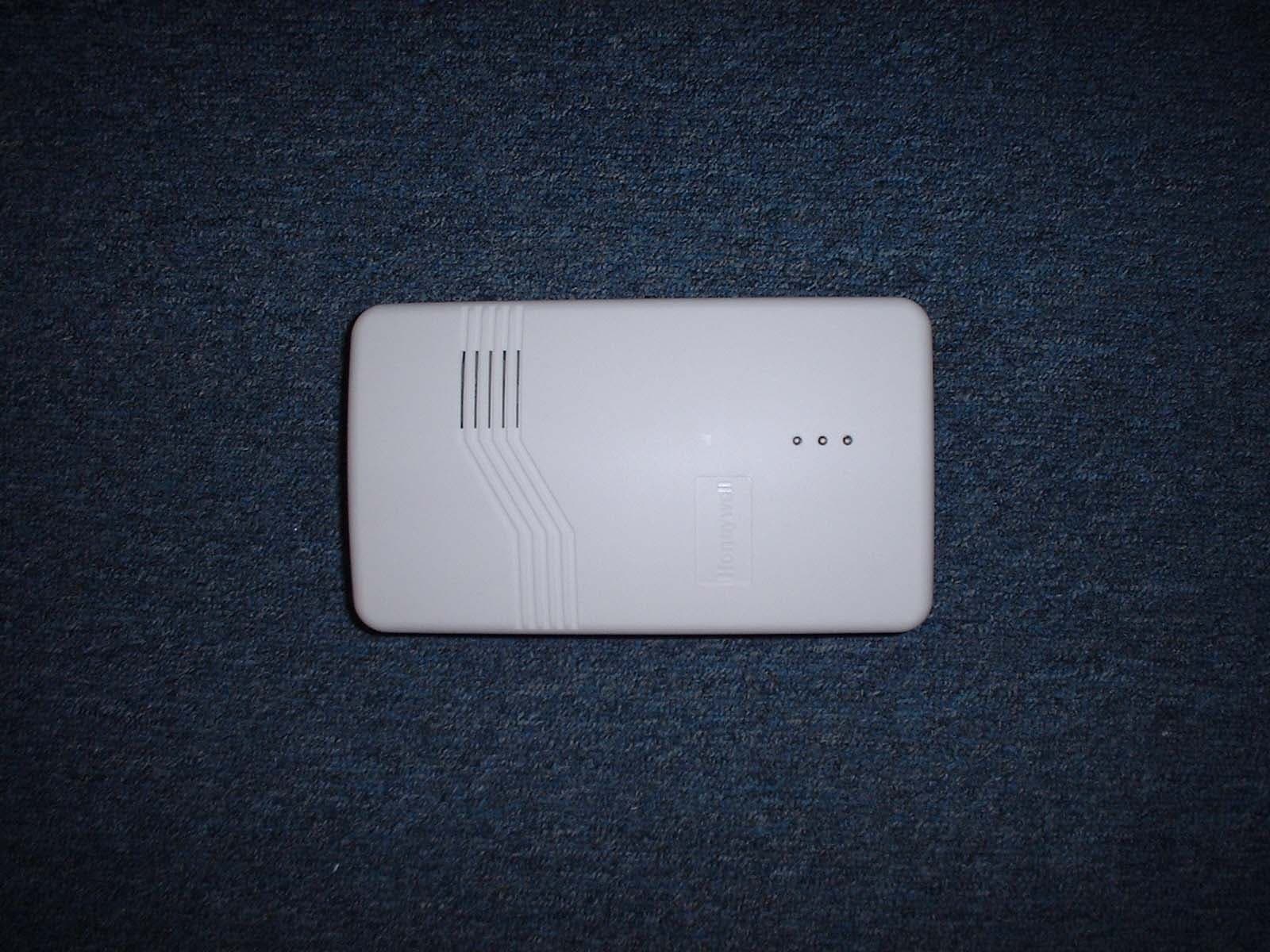
Click to zoom
Application Details
- Equipment Class
- DSR - Part 15 Remote Control/Security Device Transceiver
- Date of Grant
- Jan 05, 2005
- Application Purpose
- Original Equipment
- Date of Application
- Oct 19, 2004
- Equipment Note
- Remote alarm system accessory
- Frequency Range
- 345.00000000 - 345.00000000
- Company
- Ademco Inc.
- Country
- United States
Documents & Files
Document Text
Text extracted from the exhibit documents filed with the FCC. Open a document above to read the original.
Users Manual
ADEMCO LYNX XL SERIES ADEMCO LYNX XL SERIESADEMCO LYNX XL SERIES ADEMCO LYNX XL SERIES Security System Security SystemSecurity System Security System XL XLXL XL- -- -1000 10001000 1000 Installation and Setup Guide Installation and Setup GuideInstallation and Setup Guide Installation and Setup Guide BETA DRAFT COPY 03/19/04 K9349 3/04 Regulatory Agency Statements UL NOTICE: This is a "Grade A" residential system. FCC ID: CFSK3852 (LRR) CFS8DLLXL1000 (SRR) ACTA Product Label: AC3AL00BLXL1000 (Telephone) CANADA: 573F-182327A (LRR) CANADA: 573F-LXL1000R (SRR) CANADA: 573FXL1000T (Telephone) FCC STATEMENT THIS DEVICE COMPLIES WITH PART 15 OF FCC RULES. OPERATION IS SUBJECT TO THE FOLLOWING TWO CONDITIONS: (1) THIS DEVICE MAY NOT CAUSE HARMFUL INTERFERENCE, AND (2) THIS DEVICE MUST ACCEPT ANY INTERFERENCE RECEIVED, INCLUDING INTERFERENCE THAT MAY CAUSE UNDESIRED OPERATION. Federal Communications Commission (FCC) Part 15 Statement This equipment has been tested to FCC requirements and has been found acceptable for use. The FCC requires the following statement for your information: This equipment generates and uses radio frequency energy and if not installed and used properly, that is, in strict accordance with the manufacturer's instructions, may cause interference to radio and television reception. It has been type tested and found to comply with the limits for a Class B computing device in accordance with the specifications in Part 15 of FCC Rules, which are designed to provide reasonable protection against such interference in a residential installation. However, there is no guarantee that interference will not occur in a particular installation. If this equipment does cause interference to radio or television reception, which can be determined by turning the equipment off and on, the user is encouraged to try to correct the interference by one or more of the following measures: • If using an indoor antenna, have a quality outdoor antenna installed. • Reorient the receiving antenna until interference is reduced or eliminated. • Move the radio or television receiver away from the receiver/control. • Move the antenna leads away from any wire runs to the receiver/control. • Plug the receiver/control into a different outlet so that it and the radio or television receiver are on different branch circuits. If necessary, the user should consult the dealer or an experienced radio/television technician for additional suggestions. The user or installer may find the following booklet prepared by the Federal Communications Commission helpful: "Interference Handbook." This booklet is available from the U.S. Government Printing Office, Washington, DC 20402. The user shall not make any changes or modifications to the equipment unless authorized by the Installation Instructions or User's Manual. Unauthorized changes or modifications could void the user's authority to operate the equipment. Federal Communications Commission (FCC) Part 68 This equipment complies with Part 68 of the FCC rules. On the front cover of this equipment is a label that contains the FCC registration number and Ringer Equivalence Number (REN). You must provide this information to the telephone company when requested. This equipment uses the following USOC jack: RJ31X This equipment may not be used on telephone-company-provided coin service. Connection to party lines is subject to state tariffs. This equipment is hearing-aid compatible. Industry Canada NOTICE: The Industry Canada Label identifies certified equipment. This certification means that the equipment meets telecommunications network protective, operational and safety requirements as prescribed in the appropriate Terminal Equipment Technical Requirements document(s). The Department does not guarantee the equipment will operate to the user’s satisfaction. Before installing this equipment, users should ensure that it is permissible to be connected to the facilities of the local telecommunications company. The equipment must also be installed using an acceptable method of connection. The customer should be aware that compliance with the above conditions may not prevent degradation of service in some situations. Repairs to certified equipment should be coordinated by a representative designated by the supplier. Any repairs or alterations made by the user to this equipment, or equipment malfunctions, may give the telecommunications company to request the user to disconnect the equipment. Users should ensure for their own protection that the electrical ground connections of the power utility, telephone lines and internal metallic water pipe system, if present, are connected together, This precaution may be particularly important in rural areas. Caution: Users should not attempt to make such connections themselves but should contact appropriate electric inspection authority, or electrician, as appropriate. Ringer Equivalence Number Notice: The Ringer Equivalence Number (REN) assigned to each terminal device provides an indication of the maximum number of terminals allowed to be connected to a telephone interface. The termination on an interface may consist of any combination of devices subject only to the requirement that the sum of the Ringer Equivalence Numbers of all the devices does not exceed 5.
Cover Letter(s)
Dear Mr. Leimer, In regards to our application: Correspondence Reference Number: 28123 731 Confirmation Number: EA701849 Re: FCC ID CFS8DLLXL1000 Applicant: Honeywell International Inc. You wrote: To: [email protected] Subject: Limits The Test Report contains data for 15.231(a) limits and 15.231.(e) limits. The line item in the application is for 15.231(e). Why do you have data for both limits? Is this a 15.231(a) or 15.231(e) device? You cannot have both. Please explain. Sir, it sounds like we accidentally 'double-clicked' on " 15.231(e) " during the submission. All of our Part 15 devices that operate at 345 MHz. Operate under 15.231.a. Sorry for the confusion. Best Regards, Greg Barbato for Ken Addy
Cover Letter(s)
To: Linda Elliott Subject: RE: CFS8DLLXL1000 / EA701849 Importance: High OK, Here is the new label with the required wording. Regards, Greg Barbato 516-921-6704 Ext. 6920 MODEL: LXL1000 FCC ID: CFS8DLLXL1000 This device complies with Part 15 of the FCC Rules. Operation is subject to the following two conditions: (1) this device may not cause harmful interference, and (2) this device must accept any interference received, including interference that may cause undesired operation. Contains Transmitter Module FCC ID: CFSK3852 . ACTA Part 68 Reg. No. US: AC3AL00BLXL100 0 INDUSTRY CANADA: CANADA: 573F-LXL1000R CANADA: 573F-LXL1000R CANADA: 573F-182327A
ID Label/Location Info
Honeywell International Inc. ADEMCO Model: LXL1000 FCC ID: CFS8DLLXL1000, CFSK3852, AC3AL00BLXL1000 FCC PART 15 STATEMENT THIS DEVICE COMPLIES WITH PART 15 OF FCC RULES. OPERATION IS SUBJECT TO THE FOLLOWING TWO CONDITIONS: (1) THIS DEVICE MAY NOT CAUSE HARMFUL INTERFERENCE, AND (2) THIS DEVICE MUST ACCEPT ANY INTERFERENCE RECEIVED, INCLUDING INTERFERENCE THAT MAY CAUSE UNDESIRED OPERATION. Industry Canada: CANADA: 573F-LXL1000R, CANADA: 573F-182327A, CANADA: 573F-LXL1000T
ID Label/Location Info
MODEL: LXL1000 FCC ID: CFS8DLLXL1000 This device complies with Part 15 of the FCC Rules. Operation is subject to the following two conditions: (1) this device may not cause harmful interference, and (2) this device must accept any interference received, including interference that may cause undesired operation. Contains Transmitter Module FCC ID: CFSK3852 . ACTA Part 68 Reg. No. US: AC3AL00BLXL100 0 INDUSTRY CANADA: CANADA: 573F-LXL1000R CANADA: 573F-LXL1000R CANADA: 573F-182327A
Operational Description
EXHIBIT 1-1 CFS8DLLXL1000 FUNCTIONAL DESCRIPTION LXL1000 and LXL1010 The LXL family of alarm controls are a complete alarm control system. The LXL contains a fixed transceiver for the purpose of receiving alarm signals from remote door / window sensors such as the 5816; and arm /disarm commands from Key-fob 5804BD type devices, and or fixed wireless keypads, such as the 5839. It can also control wireless relay and wireless siren type devices as required. All messages are transmitted at 345MHz +/-82kHz using on-off keyed AM modulation. The LXL does not send regular supervision or check-in messages. It sends transmit alarm messages, control messages initiated at the keypad and messages which are a confirmation of reception of manually initiated control messages received from portable remote control transmitter. The LXL family also performs remote station alarm reporting, via a Telco modem (FCC ID: AC3AL00BLXL1000), and a control channel cellular transceiver module (FCC ID: CFSK3852) LXL model LXL1010 does not incorporate a cellular transceiver, and uses the Telco modem only.
Operational Description
EXHIBIT 2-1 CFS8DLLXL1000 Part 15 Alarm Transceiver Circuit Description RECEIVER: Incoming signals are picked up by diversity antennas: ANT3 and ANT4. ANT3 is matched by network: L11, C45, L9, C39, L8, C59, C46, L3, AND C57. ANT4 is matched by network: L12, C47, L13, C50, C55, C54, L1, AND C51. The ANT3 and ANT4 are switched by SW400 and SW403, Saw Filter FL403 provides image rejection. SW401 is the: transmit / receive switch. A single chip receiver U11 provides all the required receiver functions of: LNA, Phase locked LO, IF Stages, and Detector. Crystal YL4 is the LO’s FDE. ( 20.89375 MHz X 16 = 334.3 MHz low side injection) And Ceramic filter FL1 provides the IF Band pass. Base-band is conditioned by Op Amps; U22 and U13 before being processed by the microprocessor U15. TRANSMITTER: The Transmitter is under the control of microprocessor U15. A Single chip transmitter U12, provides all the required transmitter functions of: PLL, DRIVER, MODULATOR, and PA. TRANSMITTER U12’s FDE is Y402, The PA output is matched to 50 ohms by: L2, C171, C407, L408, and C410. R400, R426, R61, R401 and Q1 provide the required power reduction for longer duty cycle messages the transmit / receive switch SW401, feeds antenna switches SW400 and SW403, and matching network: L11, C45, L9, C39, L8, C59, C46, L3, AND C57 feeds ANT3 while matching network: L12, C47, L13, C50, C55, C54, L1, AND C51 feeds ANT4.
Operational Description
EXHIBIT 3CFS8DLLXL1000 Message protocol, timing and duty cycle calculation. SHORT MESSAGE PER 15.231 a) The data output is phase encoded Manchester which has inherent 50% duty cycle. The transmitted data rate is 4 kBs +/-0.05%, i.e. each bit is 250uS duration typical and 251.25uS max. The worst case data format consists of 120 bits, The duration of each word is 30. mSec max. Each word is transmitted 5 times at each transmission event, the words are separated (start to start) by 105mSec max.. Total max transmission time at each transmission = 452.655mSec. The duty cycle over a 100mSec measuring period is as follows: Duty Cycle = Actual RF transmission ON time / 100mSec (interval) Actual transmission ON time = 120 bits X 50% X 251.25uSec = 15.0mSec Therefore Duty cycle = 15.0 / 100 mSec = .15 = 15.0% LONG MESSAGE PER 15.231 e) The data output is phase encoded Manchester which has inherent 50% duty cycle. The transmitted data rate is 10kBs +/-0.05%, i.e. each bit is 100uS duration typical and 100.05uS max. The worst case data format consists of 440 bits, The duration of each word is 44.02 mSec max. Each word is transmitted 5 times at each transmission event, the words are separated (start to start) by 105mSec. Total max transmission time at each transmission = 464.02mSec. The transmitter is inhibited from further transmission of the long message for 15 seconds after each transmission (i.e. >30 times the transmission duration per 15.231 e)). The duty cycle over a 100mSec measuring period is calculated as follows: Duty Cycle = Actual RF transmission ON time / 100mSec (interval) Actual transmission ON time = 440 bits X 50% X 100.05uSec = = 22.011mSec Therefore Duty cycle = 22.011 / 100 mSec = .22011 = 22.01%
Schematics
SMR TPS76433 U16 N42-S764-3V3
Test Report
EXHIBIT 5 CFS8DLLXL1000 Report of Measurements. Measurements were made in accordance with the procedures and reporting requirements of ANSI C63.4-1992. The Test Set-Up (C63.4 section 10.1.3) is shown in the attached drawing. The sequence of testing (C63.4 section 10.1.7) for radiated emissions is as follows: A preliminary scan was conducted with the receiver antenna close to the EUT in order to identify the emission characteristics of the EUT (C63.4 section 8.3.1.1). The antenna and EUT were then placed at the proper separation with the EUT positioned on a non-conducting turntable. The EUT was rotated on the turntable to maximize the received signal strength, then the receiver antenna height was varied to further maximize the received reading. Thereafter, the device was again rotated to a peak output position and the antenna height was re- adjusted for maximum received signal. This procedure was re- iterated until there was no further increase in signal level. This procedure was performed with the EUT rotating in three orthogonal planes (C63.4 section 13.1.4.1) to generate a final maximum reading which is recorded on the radiated emissions result sheet. Similar measurements were made on the receiver to ensure compliance as an unintentional radiator. The results of the receiver emission measurements are in the Ademco Radio Engineering FCC file at the address above. See Exhibit 6 for list of test equipment (C63.4 section 10.1.4). Note, Spectrum Analyzer resolution bandwidths set as follows; (Video Bandwidth set greater than RBW) - For occupied bandwidth measurements, RBW = 100kHz, (This is in accordance with the minimum RBW allowed by C63.4, which requires RBW greater than 5% of the FCC required occupied bandwidth spec of 0.25% of center frequency). - For radiated emissions below 1 GHz, the RBW = 100kHz. Detector function set to peak. - For radiated emissions above 1 GHz, the RBW = 1MHz. Detector function set to peak. OCCUPIED BANDWIDTH is shown on attached plot. RADIATED EMISSIONS are recorded on attached sheet.
Test Report
ALARM DEVICE MANUFACTURING COMPANY 165 EILEEN WA Y SYOSSET, NY 11791EXHIBIT 5-3 FCC ID # CFS8DLLXL1000 Date : _10/16/2004______ Tested by : _G.Barbato___ Approved by : __K.Addy__________ Test Sample (model) : ______LXL1000_____NOTE: HIGH POWER____________________ Test method: ANSI C63.4 - 1992 Test specification: FCC Part 15, Sub-part C Notes: (1) Fo = 345MHz. (2) Detector = Peak (3) Frequency range scanned to 4 GHz. Emissions not reported were more than 20dB below the specified unit. [(Meter reading + Cable/Amp factor + Antenna factor) / 20 )] (4) Conv. Reading = 10 (5) Corr. Reading = Conv. Reading X Duty Cycle (6) Six Highest Emissions Recorded Freq. (MHz) Antenna Polarity (V/H) Meter Reading (dB uV) Cable/Amp Factor (dB) Antenna Factor (dB/M) Conv. Reading (uV/M) Duty Cycle (%) Corr. Reading (uV/M) Limit @ 3M (uV/M) 30 CABLE "A"BICONOLOG729 345h74.501.314.7833806.515.0%5071.07292 690h15.691.719.1066.815.0%10.0729 1035h23.152.322.70255.615.0%38.3500 1380h20.893.025.10281.515.0%42.2500 1725h20.003.327.55348.715.0%52.3729 2070h18.693.829.42394.015.0%59.1729 2415h17.894.131.85492.015.0%73.8729 2760 h 17.554.1 32.20492.615.0%73.9729 3105h19.175.731.75677.615.0%101.6729 3450h20.176.232.28856.115.0%128.4729 4000 CABLE "A"BICONOLOG
Test Report
ALARM DEVICE MANUFACTURING COMPANY 165 EILEEN WA Y SYOSSET, NY 11791EXHIBIT 5-3 FCC ID # CFS8DLLXL1000 Date : _10/16/2004______ Tested by : _G.Barbato___ Approved by : __K.Addy__________ Test Sample (model) : ______LXL1000__NOTE: LOW PWR________________________ Test method: ANSI C63.4 - 1992 Test specification: FCC Part 15, Sub-part C Notes: (1) Fo = 345MHz. (2) Detector = Peak (3) Frequency range scanned to 4 GHz. Emissions not reported were more than 20dB below the specified unit. [(Meter reading + Cable/Amp factor + Antenna factor) / 20 )] (4) Conv. Reading = 10 (5) Corr. Reading = Conv. Reading X Duty Cycle (6) Six Highest Emissions Recorded Freq. (MHz) Antenna Polarity (V/H) Meter Reading (dB uV) Cable/Amp Factor (dB) Antenna Factor (dB/M) Conv. Reading (uV/M) Duty Cycle (%) Corr. Reading (uV/M) Limit @ 3M (uV/M) 30 CABLE "A"BICONOLOG729 345h73.591.314.7830443.922.0%6697.77292 690h23.001.719.10154.922.0%34.1729 1035h17.172.322.70128.422.0%28.2500 1380h18.223.025.10207.022.0%45.5500 1725h20.173.327.55355.622.0%78.2729 2070h18.673.829.42393.122.0%86.5729 2415h19.174.131.85570.222.0%125.4729 2760 h 18.874.1 32.20573.522.0%126.2729 3105h19.225.731.75681.622.0%149.9729 3450h19.226.232.28767.422.0%168.8729 4000 CABLE "A"BICONOLOG
Test Report
EXHIBIT 6 CFS8DLLXL1000 Test Equipment list 1. Antenna: BICONOLOG S/N: 00029290 Cal. on: 09/14/04 Cal. due: 09/14/05 2. Spectrum Analyzer H. P. 8563E S/N:3246A00232 Cal. on: 08/23/04 Cal. due: 08/23/05
Contact Information
Applicant
Christian Fouth(Sr. Wireless Certification Engineer)
Technical Contact
Honeywell International Inc.Ken L Addy
[email protected]516-921-6704
165 Eileen Way · Syosset, New York · United States
Non-Technical Contact
Honeywell International Inc.Ken L Addy
[email protected]516-921-6704
Test Firm
Honeywell International Inc.Kenneth Addy
Technical Specifications
| # | Rule Parts | Frequency Range | Power Output |
|---|---|---|---|
| 1 | 15.231(e) | 345 MHz - 345 MHz | - |
Other Applications from Ademco Inc.

CFS8DL5800MINIV
Jan 28, 2026Wireless Alarm Transmitter
Equipment Class
DXX - Part 15 Low Power Communication Device Transmitter
CFS8DLWTS800
Jan 12, 2026Wireless Alarm Transmitter
Equipment Class
DTS - Digital Transmission SystemCFS8DLCAMWEWI1
Jul 25, 2024VX5 HD Indoor Camera
Equipment Class
DTS - Digital Transmission System
CFS8DLCAMWEWO1
Sep 17, 2023VX3 HD Outdoor Camera
Equipment Class
NII - Unlicensed National Information Infrastructure TX
CFS8DLLMD500A
Jul 20, 2023Wireless door/window contact
Equipment Class
DTS - Digital Transmission System