CFS8DLLYNXTOUCH1Wireless Control / Communicator
Ademco Inc.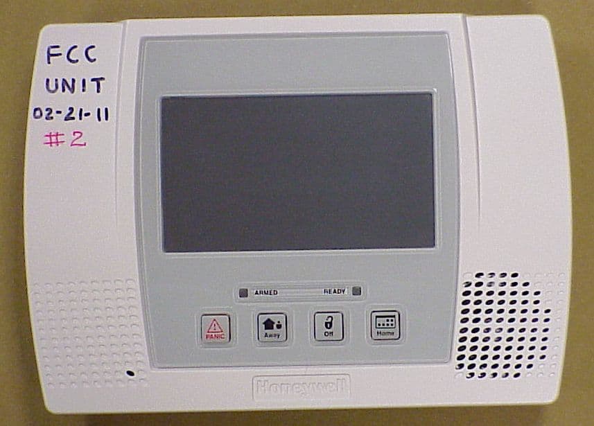
Click to zoom
Application Details
- Equipment Class
- DSR - Part 15 Remote Control/Security Device Transceiver
- Date of Grant
- Mar 14, 2011
- Application Purpose
- Original Equipment
- Date of Application
- Mar 10, 2011
- Equipment Note
- Wireless Control / Communicator
- Frequency Range
- 344.94000000 - 344.94000000
- Company
- Ademco Inc.
- Country
- United States
Documents & Files
Document Text
Text extracted from the exhibit documents filed with the FCC. Open a document above to read the original.
Users Manual
LYNX Touch Series Security Systems Installation and Setup Guide ARMEDREADY 800-06834 1/11 Rev. A LYNX Touch Installation and Setup Guide - 2 - RECOMMENDATIONS FOR PROPER PROTECTION The Following Recommendations for the Location of Fire and Burglary Detection Devices Help Provide Proper Coverage for the Protected Premises. Recommendations for Smoke and Heat Detectors With regard to the number and placement of smoke/heat detectors, we subscribe to the recommendations contained in the National Fire Protection Association's (NFPA) Standard #72 noted below. • Early warning fire detection is best achieved by the installation of fire detection equipment in all rooms and areas of the household as follows: For minimum protection a smoke detector should be installed outside of each separate sleeping area, and on each additional floor of a multi-floor family living unit, including basements. The installation of smoke detectors in kitchens, attics (finished or unfinished), or in garages is not normally recommended. • For additional protection the NFPA recommends that you install heat or smoke detectors in the living room, dining room, bedroom(s), kitchen, hallway(s), attic, furnace room, utility and storage rooms, basements and attached garages. In addition, we recommend the following: • Install a smoke detector inside every bedroom where a smoker sleeps. • Install a smoke detector inside every bedroom where someone sleeps with the door partly or completely closed. Smoke could be blocked by the closed door. Also, an alarm in the hallway outside may not wake up the sleeper if the door is closed. • Install a smoke detector inside bedrooms where electrical appliances (such as portable heaters, air conditioners or humidifiers) are used. • Install a smoke detector at both ends of a hallway if the hallway is more than 40 feet (12 meters) long. • Install smoke detectors in any room where an alarm control is located, or in any room where alarm control connections to an AC source or phone lines are made. If detectors are not so located, a fire within the room could prevent the control from reporting a fire or an intrusion. THIS CONTROL COMPLIES WITH NFPA REQUIREMENTS FOR TEMPORAL PULSE SOUNDING OF FIRE NOTIFICATION APPLIANCES. DINING KITCHEN BEDROOM BEDROOM BEDROOM BEDROOM LIVING ROOM BEDROOM BDRM DINING LIVING ROOM TV ROOM KITCHEN BEDROOM BEDROOM TO BR LVNG RM BASEMENT KTCHN . CLOSED DOOR GARAGE Smoke Detectors for Minimum Protection Smoke Detectors for Additional Protection Heat-Activated Detectors BDRM floor_plan-001-V1 Recommendations For Proper Intrusion Protection • For proper intrusion coverage, sensors should be located at every possible point of entry to a home or premises. This would include any skylights that may be present, and the upper windows in a multi-level building. • In addition, we recommend that radio backup be used in a security system. This will ensure that alarm signals can be sent to the alarm monitoring station in the event that the telephone lines are out of order (alarm signals are normally sent over the phone lines, if connected to an alarm monitoring station). LYNX Touch Installation and Setup Guide -3- Table of Contents System Features.....................................................................................................................................................5 Mounting the Control...........................................................................................................................................6 Wall Mounting ....................................................................................................................................................6 Desktop Mounting ..............................................................................................................................................6 Wiring Overview .................................................................................................................................................6 Wiring Connections...............................................................................................................................................7 AC Power and Backup Battery..........................................................................................................................9 Installing/Configuring Communications Modules......................................................................................10 General ..............................................................................................................................................................10 Connecting and Configuring Communications Modules ...............................................................................10 Installing Wireless Zones...................................................................................................................................12 General Information .........................................................................................................................................12 5800 Series Transmitter Loop Numbers.........................................................................................................12 Mechanics of Programming..............................................................................................................................15 Navigating Menus ............................................................................................................................................15 General Programming Information.................................................................................................................16 Programming ....................................................................................................................................................17 Loading Factory Defaults.................................................................................................................................17 Exitin…
Text truncated - open the document above for the full version.
Users Manual
LYNX Touch Security System User Guide ARMEDREADY Zones Arm Away Ready To Arm Arm Stay MoreDelay Phone 10:18 AM June 8, 2010 Message System 800-06894 1/11 Rev. A – 2 – Your Honeywell security system is designed for use with devices manufactured or approved by Honeywell for use with your security system. Your Honeywell security system is not designed for use with any device that may be attached to your security system's control or other communicating bus if Honeywell has not approved such device for use with your security system. Use of any such unauthorized device may cause damage or compromise the performance of your security system and affect the validity of your Honeywell limited warranty. When you purchase devices that have been manufactured or approved by Honeywell, you acquire the assurance that these devices have been thoroughly tested to ensure optimum performance when used with your Honeywell security system. – 3 – TABLE OF CONTENTS TABLE OF CONTENTSTABLE OF CONTENTS TABLE OF CONTENTS SYSTEM OVERVIEW..................................................................................................................................5 Features ...................................................................................................................................................5 General Operation...................................................................................................................................6 Quick View of System Functions ............................................................................................................9 About the Touchscreen Control ............................................................................................................10 Touchscreen Control Definitions ..........................................................................................................11 About the Display and Indicators.........................................................................................................13 Navigating Menus .................................................................................................................................15 SECURING THE PREMISES..................................................................................................................17 System Status........................................................................................................................................17 Arming the System................................................................................................................................18 Entry/Exit Delays..................................................................................................................................23 Disarming the System...........................................................................................................................25 Bypassing Protection Zones ..................................................................................................................27 Panic Keys .............................................................................................................................................29 Chime Mode...........................................................................................................................................31 Voice Mode.............................................................................................................................................32 USER FUNCTIONS...................................................................................................................................33 User Access ............................................................................................................................................33 View Events ...........................................................................................................................................37 Message Recording and Playback.........................................................................................................39 System Adjustment ...............................................................................................................................41 Clock/Calendar ......................................................................................................................................42 Scheduling User Interface ....................................................................................................................45 Reminders..............................................................................................................................................48 Speaker Phone Feature.........................................................................................................................51 Remote Phone Control Feature ............................................................................................................53 Remote Services ....................................................................................................................................55 FIRE/CO ALARM SYSTEM......................................................................................................................56 General Information..............................................................................................................................56 National Fire Protection Association’s Smoke Detector Recommendations.......................................57 Emergency Evacuation .........................................................................................................................58 SYSTEM FUNCTIONS..............................................................................................................................59 Testing the System................................................................................................................................59 Maintaining Your …
Text truncated - open the document above for the full version.
External Photos
EXHIBIT 4-1 CFS8DLLYNXTOUCH1 / 573F- LYNXTOUCH1 EXTERNAL PICTURES TOP PLASTIC: BOTTOM PLASTIC:
ID Label/Location Info
EXHIBIT 8 CFS8DLLYNXTOUCH1 / 573F-LYNXTOUCH1 LABELS ACTUAL LOCATION OF LABEL ON BACK PLASTIC; BASIC CONFIGURATION - NO GSM OPTION: THIS IS WHAT THE MAIN LABEL LOOKS LIKE IN THE GSM CONFIGURATION WITH THE AUXILIARY LABEL ADDED: EXHIBIT 8 CFS8DLLYNXTOUCH1 / 573F-LYNXTOUCH1 ENGINEERS DRAWINGS OF THE MAIN & AUXILIARY LABELS THIS IS THE MAIN LABEL: THIS IS THE AUXILIARY LABEL: THIS IS THE AUXILIARY LABEL PLACED OVER THE MAIN LABEL:
Internal Photos
EXHIBIT 4-2 CFS8DLLYNXTOUCH1 / 573F-LYNXTOUCH1 INTERNAL PHOTOS PCB IN PLASTIC: PCB REMOVED FROM PLASTIC: TOP OF PCB: BOTTOM OF PCB: EXHIBIT 4-2 (CONT.) CFS8DLLYNXTOUCH1 / 573F-LYNXTOUCH1 LYNX TOUCH CONFIGURATIONS: 1. BASIC LYNX TOUCH: ....USED FOR TELCO LINE COMMUNICATION TO CENTRAL STATION 2. LYNX TOUCH WITH GSM: ....USED FOR GSM COMMUNICATION TO CENTRAL STATION 3. LYNX TOUCH WITH INTERNET CONNECTION: ....USED FOR INTERNET COMMUNICATION TO CENTRAL STATION.
Internal Photos
EXHIBIT 4-2A LABELS ON THE CINTERION MODULE CFS8DLLYNXTOUCH1 / 573F-LYNXTOUCH1 THE CINTERION MODULE IS LABELED FROM THE MANUFACTURER WITH THE MODULE FCC & IC ID’S: THE MODULE AND ITS ANTENNA ARE MOUNTED ON A DAUGHTER BOARD: THE DAUGHTER BOARD IS MOUNTED ON A PLASTIC CARRIER: WHEN THE PRODUCT IS OPEN THIS IS WHAT YOU WILL SEE: THE DAUGHTER BOARD WITH THE GSM MODULE MOUNTED ON THE RIGHT SIDE OF THE INSIDE REAR PLASTIC.
Test Report
HONEYWELL SECURITY & CUSTOM ELECTRONICSREV L JULY 10 2 Corporate Center Drive Melville, NY 11747EXHIBIT 5-3FCC ID:CFS8DLLYNXTOUCH1 Date : 02/23/2011 Tested by : G. BARBATO Approved by : K. Eskildsen Test Sample (model) : 344.94 MHz L5000/LYNX TOUCH Test method: ANSI C63.4 - 2004 Test specification: FCC Part 15, Sub-part C and RSS 210 , Issue 7 Notes: (1) Fo = 345MHz. (2) Detector = Peak (3) Frequency range scanned to 4 GHz. Emissions not reported were more than 20dB below the specified unit. [(Meter reading + Cable/Amp factor + Antenna factor) / 20 )] (4) Conv. Reading = 10 (5) Corr. Reading = Conv. Reading X Duty Cycle (6) Six Highest Emissions Recorded Freq. (MHz) Antenna Polarity (V/H) Meter Reading (dB uV) Cable/Amp Factor (dB) Antenna Factor (dB/m) Conv. Reading (uV/M) Duty Cycle (%) Corr. Reading (uV/M) Limit @ 3M (uV/M) 30 LAST CAL 05 FEB 11 CABLE C LAST CAL 28 APR 10 BICONILOG S/N:00029390 729 344.94v76.442.314.40 45394.2 15.22% 6910.6 7292 689.88v22.753.220.00198.4 15.22% 30.2729 1034.82v22.884.424.30379.3 15.22% 57.7500 1379.76v22.554.928.40620.2 15.22% 94.4500 1724.70v22.755.529.30754.2 15.22% 114.8729 2069.64v23.336.431.101100.3 15.22% 167.5729 2414.58v22.736.932.501277.9 15.22% 194.5729 2759.52 v 23.067.4 32.501406.0 15.22% 214.0500 3104.46v22.497.932.601410.9 15.22% 214.7729 3449.40v21.579.234.501834.4 15.22% 279.2729 4000 LAST CAL 05 FEB 11 CABLE C LAST CAL 28 APR 10 BICONILOG S/N:00029390
Test Report
EXHIBIT 5.4 CFS8DLLYNXTOUCH1 / 573F-LYNXTOUCH1 OCCUPIED BANDWIDTH RBW = 30 KHz VBW = 100KHz OBW = 202.4 KHz (OBW limit = 862.35KHz @344.940 MHz)
Test Report
EXHIBIT 5-5 CFS8DLLYNXTOUCH1 / 573F-LYNXTOUCH1 Class B Radiated Emissions Honeywell - 3 m chamber Radiated Emissions 30 - 1000 MHz Operator: greg C:\Tile4\Greg_B\02-23-2011-TOUCH-3.TIL 05:05:39 PM, Wednesday, February 23, 2011 Top Horizontal LIMIT Vert Peak Quasi Peak Margin Frequency FCC_B (dBμV/m) (dBμV/m) (dB) 30.0 MHz 40 NAN NAN NAN 88.0 MHz 40 NAN NAN NAN 88.0 MHz 43.52 NAN NAN NAN 216.0 MHz 43.52 NAN NAN NAN 216.0 MHz 46.02 NAN NAN NAN 960.0 MHz 46.02 NAN NAN NAN 960.0 MHz 53.98 NAN NAN NAN 5.0 GHz 53.98 NAN NAN NAN Top Vertical LIMIT Vert Peak Quasi Peak Margin Frequency FCC_B (dBμV/m) (dBμV/m) (dB) 30.0 MHz 40 NAN NAN NAN 35.241 MHz 40 32.723 28.403 -11.597 88.0 MHz 40 NAN NAN NAN 88.0 MHz 43.52 NAN NAN NAN 142.49 MHz 43.52 31.491 30.481 -13.039 216.0 MHz 43.52 NAN NAN NAN 216.0 MHz 46.02 NAN NAN NAN 960.0 MHz 46.02 NAN NAN NAN 960.0 MHz 53.98 NAN NAN NAN 5.0 GHz 53.98 NAN NAN NAN
Test Report
EXHIBIT 5-6 CFS8DLLYNXTOUCH1 / 573F-LYNXTOUCH1 Line Conducted Emissions NOTE: THERE IS NO DATA TABLE SINCE ALL EMISSIONS GREATER THAN 20 DB BELOW THE LIMIT WILL RETURN 'NULL' DATA
Test Report
EXHIBIT 6 TEST EQUIPMENT USED CFS8DLLYNXTOUCH1 / 573F-LYNXTOUCH1 Part 15.231, ANSI C63.4 , RSS 210 This is a list of all test equipment used. Test Equipment list for Honeywell OATS & Conducted Line: Equipment Mfg Model Cal Date Cal Due Spectrum Analyzer Rohde & Schwarz FSEA20 10/19/10 10/19/11 Antenna (‘Biconilog’ ) ETS (EMCO)Lindgren 3149 0 4/28/10 04/28/11 Surge Suppressor Agilent HP11947A 05/12/10 05/12/11 LISN Com-Power LI-115 10/21/10 10/21/11 PLEASE SEE PAGE 2-5 FOR TEST EQUIPMENT TRACEABILITY If you need any additional information from Honeywell please contact: Greg Barbato RF Engineer (Acting for Ken Eskildsen) Phone (Direct): (516) 577-5863 Email: [email protected]
Test Setup Photos
EXHIBIT 5-2 CFS8DLLYNXTOUCH1 / 573F-LYNXTOUCH1 PICTURES OF THE LYNX TOUCH UNDER TEST SENSE ANT HORZ, UUT HORZ. SENSE ANT HORZ, UUT VERT. SENSE ANT HORZ, UUT OBLQ. SENSE ANT VERT, UUT HORZ. SENSE ANT VERT, UUT VERT. SENSE ANT VERT, UUT OBLQ. PICTURE OF THE SITE AT: 2 CORPORATE CENTER DRIVE MELVILLE, NY 11747
Test Setup Photos
EXHIBIT 5-2-A CFS8DLLYNXTOUCH1 / 573F-LYNXTOUCH1 PICTURE OF LINE CONDUCTED EMISSIONS TEST
Contact Information
Applicant
Christian Fouth(Sr. Wireless Certification Engineer)
Technical Contact
Honeywell International Inc.Kenneth Eskildsen
[email protected]516 577 5878
2 Corporate Center Drive · Melville · United States
Test Firm
Honeywell International Inc.Mark Schmidt
Technical Specifications
| # | Rule Parts | Frequency Range | Power Output |
|---|---|---|---|
| 1 | 15.231 | 344.94 MHz - 344.94 MHz | - |
Other Applications from Ademco Inc.

CFS8DL5800MINIV
Jan 28, 2026Wireless Alarm Transmitter
Equipment Class
DXX - Part 15 Low Power Communication Device Transmitter
CFS8DLWTS800
Jan 12, 2026Wireless Alarm Transmitter
Equipment Class
DTS - Digital Transmission SystemCFS8DLCAMWEWI1
Jul 25, 2024VX5 HD Indoor Camera
Equipment Class
DTS - Digital Transmission System
CFS8DLCAMWEWO1
Sep 17, 2023VX3 HD Outdoor Camera
Equipment Class
NII - Unlicensed National Information Infrastructure TX
CFS8DLLMD500A
Jul 20, 2023Wireless door/window contact
Equipment Class
DTS - Digital Transmission System