CFS8DLLYNXTOUCH3Wireless Control / Communicator
Ademco Inc.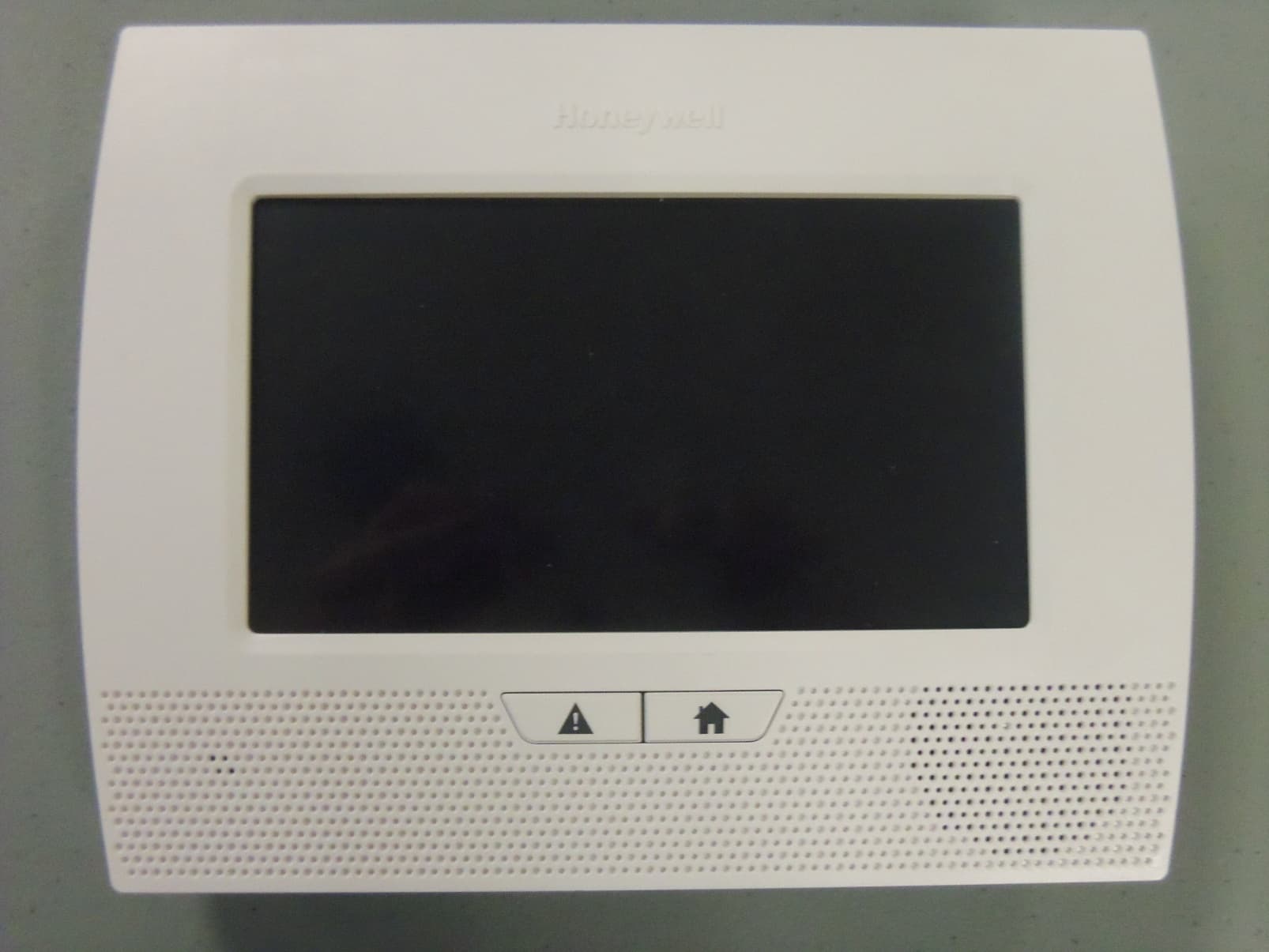
Click to zoom
Application Details
- Equipment Class
- DSR - Part 15 Remote Control/Security Device Transceiver
- Date of Grant
- May 06, 2014
- Application Purpose
- Original Equipment
- Date of Application
- May 06, 2014
- Equipment Note
- Wireless Control / Communicator
- Frequency Range
- 344.94000000 - 344.94000000
- Company
- Ademco Inc.
- Country
- United States
Documents & Files
Document Text
Text extracted from the exhibit documents filed with the FCC. Open a document above to read the original.
Users Manual
IMPORTANT INFORMATION IMPORTANT! PROPER INTRUSION PROTECTION For proper intrusion coverage, sensors should be located at every possible point of entry to a home or commercial premises. This would include any skylights that may be present, and the upper windows in a multi-level building. In addition, we recommend that radio backup be used in a security system so that alarm signals can still be sent to the Central Monitoring Station in the event that the telephone lines are out of order (alarm signals are normally sent over the phone lines). EARLY WARNING FIRE DETECTION Early warning fire detection is important in a home. Smoke and heat detectors have played a key role in reducing fire deaths in the U nited States. With regard to the number and placement of smoke/heat detectors, we subscribe to the recommendations contained in the National Fire Protection Association's National Fire Alarm Code (NFPA 72). These recommendations can be found later in this document. National Fire Protection Association Recommendations on Smoke Detectors With regard to the number and placement of smoke/heat detectors, we subscribe to the recommendations contained in the National Fire Protection Association's National Fire Alarm Code (NFPA 72). Early warning fire detection is best achieved by the installation of fire detection equipment in all rooms and areas of the household as follows: A smoke detector installed outside of each separate sleeping area, in the immediate vicinity of the bedrooms and on each additional story of the family living unit, including basements and excluding crawl spaces and unfinished attics. In addition, the NFPA recommends that you install heat or smoke detectors in the living room, dining room, bedroom(s), kitchen, hallway(s), attic, furnace room, utility and storage rooms, basements and attached garages. DINING KITCHEN BEDROOM BEDROOM BEDROOM BEDROOM LIVING ROOM BEDROOM BDRM DINING LIVING ROOM TV ROOM KITCHEN BEDROOM BEDROOM TO BR LVNG RM BASEMENT KTCHN . CLOSED DOOR GARAGE Smoke Detectors for Minimum Protection Smoke Detectors for Additional Protection Heat-Activated Detectors BDRM floor_plan-001-V1 Emergency Evacuation • FRONT • BACK • BA TH BEDR OOM KITCHEN BACK DOOR 1 FLOOR ST BEDR OOM 2 FLOOR ND BA TH BEDR OOM PORCH CLOSET BEDR OOM BEDR OOM Establish and regularly practice a plan of escape in the event of fire. The following steps are recommended by the National Fire Protection Association: 1.Position your detector or your interior and/or exterior sounders so that they can be heard by all occupants. 2.Determine two means of escape from each room. One path of escape should lead to the door that permits normal exit from the building. The other may be a window, should your path be impassable. Station an escape ladder at such windows if there is a long drop to the ground. 3. Sketch a floor plan of the building. Show windows, doors, stairs and rooftops that can be used to escape. Indicate escape routes for each room. Keep these routes free from obstruction and post copies of the escape routes in every room. 4.Assure that all bedroom doors are shut while you are asleep. This will prevent deadly smoke from entering while you escape. 5.Try the door. If the door is hot, check your alternate escape route. If the door is cool, open it cautiously. Be prepared to slam the door if smoke or heat rushes in. 6.When smoke is present, crawl on the ground. Do not walk upright, since smoke rises and may overcome you. Clearer air is near the floor. 7.Escape quickly; don't panic. 8.Establish a common meeting place outdoors, away from your house, where e veryone can meet and then take steps to contact the authorities and account for those missing. Choose someone to assure that nobody returns to the house — many die going back EXHIBIT 7A CFS8DLLYNXTOUCH3 / 573F-LYNXTOUCH3 – 2 – SYSTEM COMPATIBILITY NOTICE Your Honeywell security system is designed for use with devices manufactured or approved by Honeywell for use with your security system. Your Honeywell security system is not designed for use with any device that may be attached to your security system's keypad or other communicating bus if Honeywell has not approved such device for use with your security system. Use of any such unauthorized device may cause damage or compromise the performance of your security system and affect the validity of your Honeywell limited warranty. When you purchase devices that have been manufactured or approved by Honeywell, you acquire the assurance that these devices have been thoroughly tested to ensure optimum performance when used with your Honeywell security system. WARNING! THE LIMITATIONS OF THIS ALARM SYSTEM While this system is an advanced design security system, it does not offer guaranteed protection against burglary or other emergency. Any alarm system, whether commercial or residential, is subject to compromise or failure to warn for a variety of reasons. For example: • Intruders may gain access through unprotected openings or have the technical sophistication to bypass an alarm sensor or disconnect an alarm warning device. • Intrusion detectors (e.g. passive infrared detectors), smoke detectors, and many other sensing devices will not work without power. Battery operated devices will not work without batteries, with dead batteries, or if the batteries are not put in properly. Devices powered solely by AC will not work if their AC power supply is cut off for any reason, however briefly. • Signals sent by wireless transmitters may be blocked or reflected by metal before they reach the alarm receiver. Even if the signal path has been recently checked during a weekly test, blockage can occur if a metal object is moved into the path. • A user may not be able to reach a panic or emergency button quickly enough. • While smoke detectors have played a key role in reducing residential fire deaths in the United States, they may not activate or provide early warning for a variety of reasons in as many as 35% of all fi…
Text truncated - open the document above for the full version.
External Photos
EXHIBIT 4-1A CFS8DLLYNXTOUCH3 / 573F- LYNXTOUCH3 LYNXTOUCH3 EXTERNAL PHOTOS PLASTIC CASE FRONT: Page 1 of 3 EXHIBIT 4-1A CFS8DLLYNXTOUCH3 / 573F- LYNXTOUCH3 LYNXTOUCH3 EXTERNAL PHOTOS CONT. PLASTIC CASE BACK. Page 2 of 3 EXHIBIT 4-1A CFS8DLLYNXTOUCH3 / 573F- LYNXTOUCH3 LYNXTOUCH3 EXTERNAL PHOTOS CONT. CLOSER VIEW OF APPLIED FCC LABELS Page 3 of 3
ID Label/Location Info
EXHIBIT 8A CFS8DLLYNXTOUCH3 / 573F- LYNXTOUCH3 LABEL INFORMATION EXACT LOCATION OF THE LABEL: CASE BACK ENGINEER'S DRAWING OF THE LABEL: : PAGE 1 OF 1
Internal Photos
EXHIBIT 4-2A CFS8DLLYNXTOUCH3 / 573F-LYNXTOUCH3 LYNXTOUCH3 INTERNAL PHOTOS CASE OPEN NOTES: 1: GSM Module not installed. 2: WiFi Module not installed. 3: Z-Wave Module not installed. Page 1 of 6 EXHIBIT 4-2A CFS8DLLYNXTOUCH3 / 573F-LYNXTOUCH3 LYNXTOUCH3 INTERNAL PHOTOS CONT. CASE OPEN NOTES: Main Security PCB Assembly un-mounted Page 2 of 6 EXHIBIT 4-2A CFS8DLLYNXTOUCH3 / 573F-LYNXTOUCH3 LYNXTOUCH3 INTERNAL PHOTOS CONT. INTERIOR PLASTIC INSERT, LCD, & PCA NOTES: 1: Main Security PCB Assembly removed from case 2: This is a back view of the display. Page 3 of 6 EXHIBIT 4-2A CFS8DLLYNXTOUCH3 / 573F-LYNXTOUCH3 LYNXTOUCH3 INTERNAL PHOTOS CONT. PCA BOTTOM SIDE NOTES: 1: Main Security PCB Assembly removed from case (Bottom side view, from display side). Page 4 of 6 EXHIBIT 4-2A CFS8DLLYNXTOUCH3 / 573F-LYNXTOUCH3 LYNXTOUCH3 INTERNAL PHOTOS CONT. PCA TOP SIDE NOTES: 1: Main Security PCB Assembly removed from case ( Closer view of top side ). Page 5 of 6 EXHIBIT 4-2A CFS8DLLYNXTOUCH3 / 573F-LYNXTOUCH3 LYNXTOUCH3 INTERNAL PHOTOS CONT. KEYPAD PCA PLASTIC INSERT, LCD NOTES: 1: Main Security PCB Assembly removed from case ( Closer view of top side ). Keypad & LED PCB Assembly/ Main Security Assembly/ Display Mounting bracket Display, rear view Page 6 of 6
Test Report
EXHIBIT 5-1A CFS8DLLYNXTOUCH3 / 573F-LYNXTOUCH3 REPORT OF MEASUREMENTS Measurements for the Intentional Radiator, and OBW were made in accordance with the procedures and reporting requirements at: Honeywell's OATS ( FCC No: 152762 & IC No:573F-1 which is located at: 2 Corporate Center Drive, Melville, NY 11747 Measurements were made in accordance with the procedure and reporting requirements of ANSI C63.4-2003. The Test Set-Up (C63.4 section 10.1.3) is shown in EXHIBIT 5-2: "Test Setup Photos". The sequence of testing (C63.4 section 10.1.7) for radiated emissions is as follows: A preliminary scan was conducted with the receiver antenna close to the EUT in order to identify the emission characteristics of the EUT (C63.4 section 8.3.1.1). The antenna and EUT were then placed at the proper separation (3 Meters) with the EUT positioned at 80 cm on a non- conducting turntable. The EUT was rotated on the turntable to maximize the received signal strength, and then the receiver antenna height was varied between one (1) and four (4) Meters to further maximize the received reading. Thereafter, the device was again rotated to a peak output position and the antenna height was re-adjusted for maximum received signal. This procedure was re-iterated until there was no further increase in signal level. This procedure was performed with the EUT rotating in three orthogonal planes (C63.4 section 13.1.4.1) to generate a final maximum reading which is recorded on the radiated emissions result sheet. Similar measurements were made on the receiver to ensure compliance as an unintentional radiator. Note: The Spectrum Analyzer resolution bandwidths were set as follows: (Video Bandwidth is always set 3X greater than RBW) For Short Range Radio occupied bandwidth measurements, RBW = 30 kHz and VBW = 100 kHz. For radiated emissions below 1 GHz, the RBW = 100 kHz. Detector function set to peak. For radiated emissions above 1 GHz, the RBW = 1 MHz. Detector function set to peak. TRANSMITTER RADIATED EMISSIONS are recorded in "EXHIBIT 5-3". OCCUPIED BANDWIDTH is recorded in "EXHIBIT 5-4". TEST EQUIPMENT (per C634. section 10.1.4) is recorded in "EXHIBIT 6". PAGE 1 OF 1
Test Report
EXHIBIT 5-3A CFS8DLLYNXTOUCH3 / 573F-LYNXTOUCH3 SHORT RANGE RADIO RADIATED EMISSIONS NOTE: THE SHORT RANGE RADIO WAS OPERATED IN "DIVERSITY MODE" FOR THIS TEST, AND THE SPECTRUM ANALYZER WAS SET TO MAX HOLD. THUS THIS DATA INDICATES THE WORST CASE FOR BOTH ANTENNAS. HONEYWELL SECURITY & CUSTOM ELECTRONICS REV 07/23/2013-O 2 Corporate Center Drive Melville, NY 11747 EXHIBIT 5-3 FCC ID: CFS8DL L7000 Date : 24-Feb 2014 Tested by: BARTOLOTTI Approved by: K. Eskildsen Test Sample (model): L7000 Test method: ANSI C63.4 - 2003 Test specification: FCC Part 15, Sub-part C and RSS 210 , Issue 8 Notes: (1) Fo: 344.94 PRESCAN: (2) Detector = Peak SENSE / UUT: EL cm): AZ (deg): Meter Reading (dB uV): (3) Frequency range scanned to 4 GHz. V/V 120.0 262.0 72.08 ( Emissions not reported were more than 20dB below the specified unit ). H/V 185.0 0.0 68.87 [(Meter reading + Cable/Amp factor + Antenna factor) / 20 )] V/H 0.0 267.0 62.50 (4) Conv. Reading = 10 H/H 220.0 30.0 72.96 (5) Corr. Reading = Conv. Reading X Duty Cycle V/O 132.0 66.0 74.96 (6) Six Highest Emissions Recorded H/O 0.0 0.0 66.34 Freq. (MHz): Sense Antenna Polarity (V/H): THE ORENTATION OF THE UUT (V,H,O,): Meter Reading (dB uV): Cable/Amp Factor (dB): Antenna Factor (dB/m): Conv. Reading (uV/M): Duty Cycle (%): Corr. Reading (uV/M): Limit @ 3M (uV/M): 344.94 V O 74.96 2.5 14.90 41,495.4 16.0% 6639.3 7,289 689.88 H H 43.75 3.7 19.20 2,155.3 16.0% 344.8 729 1034.82 V H 30.61 4.7 24.80 1,012.7 16.0% 162.0 500 1379.76 H H 35.14 5.6 24.90 1,916.5 16.0% 306.6 500 1724.70 H H 35.81 6.3 27.70 3,079.6 16.0% 492.7 729 2069.64 V O 33.77 7.3 30.70 3,854.8 16.0% 616.8 729 2414.58 V H 32.60 8.1 31.80 4,197.6 16.0% 671.6 729 2759.52 H H 28.87 8.6 31.40 2,779.7 16.0% 444.8 500 3104.46 H H 30.84 9.1 31.50 3,736.8 16.0% 597.9 729 3449.40 V O 28.76 10.0 33.90 4,280.6 16.0% 684.9 729 4000 LAST CAL 15 MAR 13 CABLE D LAST CAL 08-JULY-13 BICONILOG S/N:00029390 LYNXTOUCH3 LYNXTOUCH3 Page 1 of 1
Test Report
EXHIBIT 5-4A CFS8DLLYNXTOUCH3/ 573F-LYNXTOUCH3 OCCUPIED BANDWIDTH OCCPUIED BANDWIDTH: 187.5 kHz PAGE 1 OF 1
Test Report
EXHIBIT 5-5A CFS8DLLYNXTOUCH3 / 573F-LYNXTOUCH3 LYNXTOUCH3 - CLASS B RADIATED EMISSIONS The LYNXTOUCH3 contains a receiver (unintentional radiator). A check for radiated emissions is done to verify the level of radiation is insignificant. Page 1 of 3 EXHIBIT 5-5A CFS8DLLYNXTOUCH3 / 573F-LYNXTOUCH3 LYNXTOUCH3 - CLASS B RADIATED EMISSIONS CONT. HORIZONTAL DATA Page 2 of 3 EXHIBIT 5-5A CFS8DLLYNXTOUCH3 / 573F-LYNXTOUCH3 LYNXTOUCH3 - CLASS B RADIATED EMISSIONS CONT. VERTICAL DATA Page 3 of 3
Test Report
EXHIBIT 5-6A CFS8DLLYNXTOUCH3 / 573F-LYNXTOUCH3 CLASS B CONDUCTED EMISSIONS NOTE 1: THERE IS NO DATA TABLE SINCE DATA IS SUFFICIENTLY IN SPEC THAT PROGRAM RETURNS NULL VALUES. NOTE 2 : THERE IS NO AVERAGE DATA PRESENTED BECAUSE THE PEAK SCAN RETURNED NULL DATA. LINE 1 (PHASE): Page 1 of 2 EXHIBIT 5-6A CFS8DLLYNXTOUCH3 / 573F-LYNXTOUCH3 CLASS B CONDUCTED EMISSIONS CONT. LINE 2 (NEUTRAL): Page 2 of 2
Test Report
EXHIBIT 6A CFS8DLLYNXTOUCH3 / 573F-LYNXTOUCH3 LYNXTOUCH3 TEST EQUIPMENT USED Part 15.231, ANSI C63.4, RSS 210 This is a list of all test equipment used. Note: Calibration Certificates are on following pages. Test Equipment list for Honeywell OATS & Conducted Line EQUIPMENT: MANUFACTURER: MODEL: CAL DATE: CAL DUE DATE: Spectrum Analyzer Rohde & Schwarz FSEA20 10/14/2013 10/14/2014 Antenna ('Biconilog') ETS (EMCO)Lindgren 3149 / SN: 00045682 07/08/2013 07/08/2014 LISN COM-POWER LI-115 10/17/2013 10/17/2014 If you need any additional information from Honeywell, please contact: Andrew Roussin, Engineer (Acting for Mark Schmidt) Phone (Direct): 516-577-5935 Email: [email protected] Page 1 of 1
Test Setup Photos
EXHIBIT 5-2A CFS8DL LYNXTOUCH3 / 573F- LYNXTOUCH3 PICTURES OF TEST SETUP & TEST SITE Section 2.1093(c) Photo of the test setup shall be provided. PICTURES OF THE TEST SETUP SENSE HORZ, UUT HORZ SENSE HORZ, UUT VERT SENSE HORZ, UUT OBQ SENSE VERT, UUT HORZ SENSE VERT, UUT VERT SENSE VERT, UUT OBQ PAGE 1 OF 3 EXHIBIT 5-2A CFS8DL LYNXTOUCH3 / 573F- LYNXTOUCH3 PICTURES OF TEST SETUP & TEST SITE RADIATED EMISSIONS TEST SETUP RADIATED EMISSIONS TEST SETUP HONEYWELL’S 3 METER OATS AT: 2 Corporate Center Drive,Melville, NY 11747 PAGE 2 OF 3 EXHIBIT 5-2A CFS8DL LYNXTOUCH3 / 573F- LYNXTOUCH3 PICTURES OF TEST SETUP & TEST SITE CONDUCTED EMISSIONS TEST SETUP PAGE 3 OF 3
Contact Information
Applicant
Christian Fouth(Sr. Wireless Certification Engineer)
Technical Contact
Honeywell International Inc.Stanley Albrechtsen
[email protected]516 577 5860
2 Corporate Center Drive · Melville, New York · United States
Non-Technical Contact
Honeywell International Inc.Mark Schmidt
[email protected]5166775939
Test Firm
Honeywell International Inc.Mark Schmidt
Technical Specifications
| # | Rule Parts | Frequency Range | Power Output |
|---|---|---|---|
| 1 | 15.231 | 344.94 MHz - 344.94 MHz | - |
Other Applications from Ademco Inc.

CFS8DL5800MINIV
Jan 28, 2026Wireless Alarm Transmitter
Equipment Class
DXX - Part 15 Low Power Communication Device Transmitter
CFS8DLWTS800
Jan 12, 2026Wireless Alarm Transmitter
Equipment Class
DTS - Digital Transmission SystemCFS8DLCAMWEWI1
Jul 25, 2024VX5 HD Indoor Camera
Equipment Class
DTS - Digital Transmission System
CFS8DLCAMWEWO1
Sep 17, 2023VX3 HD Outdoor Camera
Equipment Class
NII - Unlicensed National Information Infrastructure TX
CFS8DLLMD500A
Jul 20, 2023Wireless door/window contact
Equipment Class
DTS - Digital Transmission System