CFS8DLPROINDMVIndoor Motion Viewer
Ademco Inc.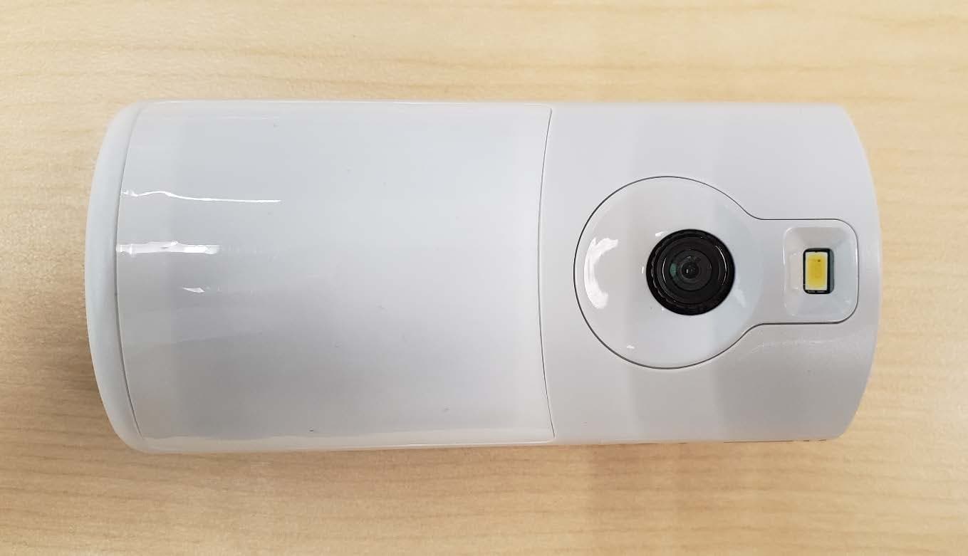
Click to zoom
Application Details
- Equipment Class
- DSS - Part 15 Spread Spectrum Transmitter
- Date of Grant
- Feb 23, 2020
- Application Purpose
- Original Equipment
- Date of Application
- Jan 28, 2020
- Equipment Note
- Indoor Motion Viewer
- Frequency Range
- 904.50000000 - 926.10000000
- Company
- Ademco Inc.
- Country
- United States
Documents & Files
Document Text
Text extracted from the exhibit documents filed with the FCC. Open a document above to read the original.
Users Manual
PROINDMV Indoor Motion Viewer Installation and Setup Guide General Information The PROINDMV is a battery powered, wireless indoor motion detector with a built-in video camera designed for use with Honeywell Home Security Systems. The detector is powered by 3 CR123A Lithium batteries that provide up to 4 years of battery life. NOTE: Installation shall be done in accordance with the National Electrical Code, NFPA 70. Features • No wiring or remote power required. Fully portable battery powered camera allows for flexibility in selecting locations • Provides video stream and live video viewing functionality • Spread Spectrum, Interactive, AES Encrypted Wireless technology provides optimum signal integrity and security • CMOS camera sensor with a wide angle 90° lens • Night vision with one white LED • Fresnel lens motion detection: 39.37ft (12m) 90° detection pattern • Camera sends color video Installation Guidelines Programming and RF testing should be done while the device is in its intended mounting location to ensure good communication between the control panel and the device. Mounting Considerations • Use proper tools and hardware. • Mount indoors in a temperature-controlled environment. • Mount camera 7.5ft (2.3m) above the floor. • Do not aim detector at windows, especially those that let in direct sunlight, or at heat sources such as fireplaces, radiators and heating vents. • The detector should be installed opposed to an access mount or asset you need to protect. • Do not aim detector at moving objects such as fans. • Do not paint or cover the detection or camera lens. Mounting (Open/Close) the PROINDMV 1. Separate the rear case/wall mount from the PROINDMV by pressing the latch on the bottom of the case and rotating out. 2. Secure the rear case/wall mount in the desired location with the two provided screws (See Mounting Options section below). NOTE: MUST be mounted on a stud, solid wall, or with a robust wall anchor. 3. Slide the PROINDMV onto the rear case/wall mount bracket. Mounting Options NOTE: Before mounting permanently, conduct a Sensor Walk Test (see the controller’s instructions) to verify adequate signal strength and adjust the device location and orientation as necessary. The PROINDMV can be mounted on the wall or in corners: • [A] = Wall Mounting Holes • [B] = Corner Mounting Holes • The rear tamper plate MUST be mounted to a stud, sold wood, or with a robust wall anchor. NOTE: Do not aim detector at windows, especially those that let in direct sunlight, or at heat sources such as fireplaces, radiators and heating vents. Detection Patterns Enrolling the Detector 1. Use AlarmNet 360 to program (www.alarmnet360.com) 2. When prompted, insert the batteries or, if powered, open and close again. 3. LED flashes rapidly at power up. After enrolling, verify adequate signal strength by conducting a sensor test (see the controller’s instructions) with the device in its intended mounting location. Adjust the device location and orientation as necessary. Walk Testing After power up and enrollment, activate the Walk Test Mode with the controller. Walk Test mode is entered/exited through “Tools” menu of the control panel. Select the Test mode to make the PROINDMV enter Walk Test. NOTE: The system must be disarmed. The system can only be armed after exiting the Walk Test mode. Replacing the Batteries Use only Resideo 300-09028, DURACELL DL123A or PANASONIC CR-123A, CR-123APA/B, CR123PE/BA batteries. BATTERY CAUTION: Risk of fire, explosion and burns. Do not recharge, disassemble, heat above 212° F (100° C) or incinerate. Dispose of used batteries properly. Keep away from children. Specifications Electrical Battery .............................................................................................................................................................................................................................. Three (3) 3V Lithium batteries Battery Part Number............................................................................................ Resideo 300-09028, DURACELL DL123A; PANASONIC CR-123A, CR-123APA/B, CR-123PA/BA Nominal voltage .......................................................................................................................................................................................................................................................... 3 V Low battery threshold .............................................................................................................................................................................................................................................. 2.7 V Estimated battery life .................................................................................................................................................................................................................................. Up to 4 years Current consumption ...................................................................................................................................................................................... Standby (1h average) 85 μA/Max 350 mA Radio Properties Wiselink® technology Radio type .................................................................................................................................................................................................................. Spread spectrum RF bidirectional Operating frequency .............................................................................................................................................................................................................. 915 MHz (USA & Canada) Transmission security ............................................................................................................................................................................................................. AES algorythm encryption Supervision ..................…
Text truncated - open the document above for the full version.
Cover Letter(s)
2 Corporate Center Drive Melville, NY 11747 516-577-2000 Request for Confidentiality Date: 12/06/2019 Subject: Confidentiality Request for: CFS8DLPROINDMV Pursuant to FCC 47 CFR 0.457(d) and 0.459 and IC RSP-100, Section 9.4, the applicant requests that a part of the subject FCC application be held confidential. Type of Confidentiality Requested Exhibit Short Term Permanent Block Diagrams Short Term External Photos Short Term Permanent* 1 Internal Photos Short Term Permanent Circuit Description/Theory of Operation Short Term Permanent Parts List & Placement/BOM Short Term Permanent Tune-Up Procedure Short Term Permanent Schematics Short Term Test Setup Photos Short Term Permanent* 3 User’s Manual Ademco Inc. has spent substantial effort in developing this product and it is one of the first of its kind in industry. Having the subject information easily available to "competition" would negate the advantage they have achieved by developing this product. Not protecting the details of the design will result in financial hardship. Permanent Confidentiality: The applicant requests the exhibits listed above as permanently confidential be permanently withheld from public review due to materials that contain trade secrets and proprietary information not customarily released to the public. Short-Term Confidentiality: The applicant requests the exhibits selected above as short term confidential be withheld from public view for a period of 180 2 days from the date of the Grant of Equipment Authorization and prior to marketing. This is to avoid premature release of sensitive information prior to marketing or release of the product to the public. Applicant is also aware that they are responsible to notify ACB in the event information regarding the product or the product is made available to the public. ACB will then release the documents listed above for public disclosure pursuant to FCC Public Notice DA 04-1705. NOTE for Industry Canada Applications: IC currently only distinguishes Permanent Confidentiality exhibits as shown above. Short Term confidentiality is not considered applicable to IC applications. Sincerely, By: ___ _/ Hardware Engineer__ __Michael Antola___________ (Signature/Title 3 ) (Print name) 1 - The asterisked items (*) require further information to be provided to ACB before permanent confidentiality will be extended to these exhibits. Please refer to FCC KDB 726920 and the specific Document link for D01 found at: https://apps.fcc.gov/oetcf/kdb/forms/FTSSearchResultPage.cfm?switch=P&id=41731 and review section II, 3) regarding specific information that must accompany these requests. 2 - Please refer to http://acbcert.com/documents/misc-docs/Memo-Short-Term-Vs-Standard-Confidentiality.pdf for complete details. 3 - Must be signed by applicant contact given for applicant on the FCC site, or by the authorized agent if an appropriate authorized agent letter has been provided. Letters should be placed on appropriate letterhead.
Cover Letter(s)
2 Corporate Center Drive Melville, NY 11747 516-577-2000 CFS8DLPROINDMV FCC COVER LETTER Date: 12/06/2019 To Whom It May Concern: This letter is to inform you of our request for a new certification for our transceiver known as CFS8DLPROINDMV. The transceiver will operate under Part 15.247. Regards, X Michael Antola
External Photos
EXHIBIT 4-1 External Photos CFS8DLPROINDMV / 573F-PROINDMV Page 1 of 6 PROINDMV EXTERNAL PHOTOS CASE EXTERIOR FRONT EXHIBIT 4-1 External Photos CFS8DLPROINDMV / 573F-PROINDMV Page 2 of 6 REAR EXHIBIT 4-1 External Photos CFS8DLPROINDMV / 573F-PROINDMV Page 3 of 6 LEFT SIDE EXHIBIT 4-1 External Photos CFS8DLPROINDMV / 573F-PROINDMV Page 4 of 6 RIGHT SIDE EXHIBIT 4-1 External Photos CFS8DLPROINDMV / 573F-PROINDMV Page 5 of 6 TOP EXHIBIT 4-1 External Photos CFS8DLPROINDMV / 573F-PROINDMV Page 6 of 6 BOTTOM
ID Label/Location Info
EXHIBIT 8 Label Information CFS8DLPROINDMV / 573F-PROINDMV Page 1 of 2 LABEL INFORMATION EXACT LOCATION OF THE LABEL Label is located on the inside cover of the device in the location shown below: FCC/IC ID’s Location EXHIBIT 8 Label Information CFS8DLPROINDMV / 573F-PROINDMV Page 2 of 2 LABEL
Internal Photos
EXHIBIT 4-2 Internal Photos CFS8DLPROINDMV / 573F-PROINDMV Page 1 of 7 PROINDMV INTERNAL PHOTOS CASE INTERIOR REAR W/ COVER REMOVED, BATTERY COMPARTMENT EXHIBIT 4-2 Internal Photos CFS8DLPROINDMV / 573F-PROINDMV Page 2 of 7 CASE INTERIOR W/ COVER REMOVED, SIDE VIEW EXHIBIT 4-2 Internal Photos CFS8DLPROINDMV / 573F-PROINDMV Page 3 of 7 CASE INTERIOR W/ COVER REMOVED, SIDE VIEW EXHIBIT 4-2 Internal Photos CFS8DLPROINDMV / 573F-PROINDMV Page 4 of 7 CASE INTERIOR FRONT W/ PCB INSTALLED EXHIBIT 4-2 Internal Photos CFS8DLPROINDMV / 573F-PROINDMV Page 5 of 7 CASE INTERIOR W/ PCB INSTALLED, COVER REMOVED EXHIBIT 4-2 Internal Photos CFS8DLPROINDMV / 573F-PROINDMV Page 6 of 7 MAIN PCB - TOP ANTENNA EXHIBIT 4-2 Internal Photos CFS8DLPROINDMV / 573F-PROINDMV Page 7 of 7 MAIN PCB - BOTTOM
RF Exposure Info
EXHIBIT 5-2CFS8DLPROINDMV / 573F-PROINDMV MPE CALCULATIONS - FCC 1.0 APPLICANT: DATE:12/6/2019 NAME OF APPLICANT:Ademco Inc. FCC ID:CFS8DLPROINDMV 2.0 FCC RULES CONCERNING MAXIMUM PERMISSIBLE RF EXPOSURE: BAND 900MHz BAND:CH No:FREQ(Mhz)TRP dbm MAX COND. PWR (dBm) ANTENNA GAIN(db): DUTY FACTOR (dB)MAX AVG EIRP (mW)FRISS mW/CM 2 :EXP LIMIT mW/CM 2 : % OF LIMIT: 900MHzN/A904.5N/A19.542.20.00149.2790.02969820.6034.9251 4.9251 4.0 RESULTS: TEST RESULT: PASS § CFR 47 1.1310 Radiofrequency radiation exposure limits. The criteria listed in table 1 shall be used to evaluate the environmental impact of human exposure to radiofrequency (RF) radiation as specified in § 1.1307(b), except in the case of portable devices which shall be evaluated according to the provisions of § 2.1093 of this chapter. Further information on evaluating compliance with these limits can be found in the FCC’s OST/OET Bulletin Number 65, ‘‘Evaluating Compliance with FCC-Specified Guidelines for Human Exposure to Radiofrequency Radiation.’’ NOTE TO INTRODUCTORY PARAGRAPH: These limits are generally based on recommended exposure guidelines published by the National Council on Radiation Protection and Measurements (NCRP) in ‘‘Biological Effects and Exposure Criteria for Radiofrequency Electromagnetic Fields,’’ NCRP Report No. 86, Sections 17.4.1, 17.4.1.1, 17.4.2 and 17.4.3. Copyright NCRP, 1986, Bethesda, Maryland 20814. In the frequency range from 100 MHz to 1500 MHz, exposure limits for field strength and power density are also generally based on guidelines recommended by the American National Standards Institute (ANSI) in Section 4.1 of ‘‘IEEE Standard for Safety Levels with Respect to Human Exposure to Radio Frequency Electromagnetic Fields, 3 kHz to 300 GHz,’’ ANSI/IEEE C95.1–1992, Copyright 1992 by the Institute of Electrical and Electronics Engineers. FCC GENERAL POPULATION / UNCONTROLED EXPOSURE LIMITS: FOR 300 MHz to 1,500 MHz use F / 1500 mW/cm 2 ; FOR 1,500 to 100,000 MHz use 1 mW/cm 2 EQUATIONS: MAX AVG EIRP (mW) = 10 {(MAX COND PWR. + ANT GAIN + DUTY FACTOR)/10)} THE FRIIS TRANSMISSION EQUATION = EIRP X DUTY CYCLE / ( 4 X PI X 20 CM 2 ) FCC ID 3.0 UUT POWER OUTPUT / ANTENNA GAIN / SEPARATION DISTANCE The maximum output power from Exhibit 5-1 is measured as 19.54 dBm. The max antenna gain is 2.2 dBi Assumed separation distance is 20cm 3.1 MPE CALCULATIONS: CALCULATIONS: BANDS AND FCC IDs In the configuration tested the EUT complied with the standards specified above. MAXIMUM MPE OF THE RF6 MODULE AS % OF LIMIT IS: CFS8DLPROINDMV EXHIBIT 5-2CFS8DLPROINDMV / 573F-PROINDMV MPE CALCULATIONS - IC 1.0 APPLICANT: DATE:12/6/2019 NAME OF APPLICANT:Ademco Inc. IC NUMBER:573F-PROINDMV 2.0 IC RULES CONCERNING MAXIMUM PERMISSIBLE RF EXPOSURE: BAND 900MHz BAND:CH No:FREQ(Mhz)TRP dbm MAX COND. PWR (dBm) ANTENNA GAIN(db): DUTY FACTOR (dB)MAX AVG EIRP (mW)FRISS mW/CM 2 :EXP LIMIT mW/CM 2 : % OF LIMIT: 900MHzN/A904.5N/A19.542.20.00149.2790.02969820.27310.8723 10.8723 4.0 RESULTS: TEST RESULT: PASS RSS-102 § 2.5.2 Exemption Limits for Routine Evaluation - RF Exposure Evaluation. RF exposure evaluation is required if the separation distance between the user and/or bystander and the device’s radiating element is greater than 20 cm, except when the device operates as follows: • at or above 300 MHz and below 6 GHz and the source-based, time-averaged maximum e.i.r.p. of the device is equal to or less than 1.31 x 10 -2 ƒ 0.6834 W (adjusted for tune-up tolerance), where ƒ is in MHz; In these cases, the information contained in the RF exposure technical brief may be limited to information that demonstrates how the e.i.r.p. was derived. 3.0 UUT POWER OUTPUT AND ANTENNA GAIN The maximum output from Exhibit 5-1 is measured as 19.54 dBm. The max antenna gain is 2.2 dBi The max time-averaged EIRP per 2.0 above is 1.31 x 10 -2 x 904.5 0.6834 (W) = 1.373W = 1373 mW. The power density at 20cm corresponding to 1373 mW EIRP is N/(4 x π x d 2 ) or 1373/(4*π*20 2 ) = 0.273 mW/cm 2 3.1 MPE CALCULATIONS: IC GENERAL POPULATION / UNCONTROLED EXPOSURE LIMITS: FROM 300 MHz to 6 GHz use (1.31 x 10 -2 ) x f 0.6834 for max EIRP(W) EQUATIONS: MAX AVG EIRP (mW) = 10 {(MAX COND PWR. + ANT GAIN + DUTY FACTOR)/10)} THE FRIIS TRANSMISSION EQUATION = EIRP X DUTY CYCLE / ( 4 X PI X 20 cm 2 ) MAXIMUM MPE OF THE RF6 MODULE AS % OF LIMIT IS: In the configuration tested the EUT complied with the standards specified above. CALCULATIONS: BANDS AND IC NUMBERS IC NUMBER: 573F-PROINDMV
Test Report
849 NW STATE ROAD 45 PHONE: 352.472.5500 NEWBERRY, FL 32669 USA EMAIL: [email protected] WEB: HTTP://WWW.TIMCOENGR.COM An IIA Company FCC PART 15.247 & IC RSS-247 900MHz FHSS Test Report APPLICANT ADEMCO INC. ADDRESS 2 CORPORATE CENTER DRIVE SUITE 1009040, MELVILLE NY 11747 FCC ID CFS8DLPROINDMV IC 573F-PROINDMV MODEL NUMBER PROINDMV PRODUCT DESCRIPTION INDOOR MOTION VIEWER DATE SAMPLE RECEIVED 8/1/2019 FINAL TEST DATE 8/22/2019 TESTED BY Tim Royer TEST RESULTS ☒ PASS ☐ FAIL Report Number Report Version Description Issue Date 2068UT19_TestReport_ Rev1 Initial Issue 11/12/2019 THE ATTACHED REPORT SHALL NOT BE REPRODUCED EXCEPT IN FULL WITHOUT THE WRITTEN APPROVAL OF TIMCO ENGINEERING, INC. TABLE OF CONTENTS GENERAL REMARKS ........................................................................................................ 3 GENERAL INFORMATION ................................................................................................ 4 EUT INFORMATION .............................................................................................................. 4 PERIPHERALS USED IN TESTING ............................................................................................... 4 RESULTS SUMMARY ........................................................................................................ 5 FREQUENCY RANGE(S) OF EUT ................................................................................................ 5 OCCUPIED BANDWIDTH ................................................................................................. 6 TEST DATA: 20 DB OCCUPIED BANDWIDTH MEASUREMENT TABLE .................................................... 6 RESULTS: PASS ................................................................................................................ 6 TEST DATA: 99% OCCUPIED BANDWIDTH MEASUREMENT TABLE ...................................................... 6 TEST DATA: 20 DB OBW LOW END OF BAND PLOT ..................................................................... 7 TEST DATA: 20 DB OBW MIDDLE OF BAND PLOT ....................................................................... 8 TEST DATA: 20 DB OBW HIGH END OF BAND PLOT ..................................................................... 9 TEST DATA: 99% OBW LOW END OF BAND PLOT ..................................................................... 10 TEST DATA: 99% OBW MIDDLE OF BAND PLOT ....................................................................... 11 TEST DATA: 99% OBW HIGH END OF BAND PLOT .................................................................... 12 FHSS REQUIREMENTS ...................................................................................................13 TEST DATA: FHSS CHANNEL SEPARATION MEASUREMENT TABLE .................................................... 14 TEST DATA: NUMBER OF HOPPING CHANNELS MEASUREMENT TABLE ................................................ 14 TEST DATA: HOPPING CHANNEL OCCUPANCY TIME MEASUREMENT TABLE .......................................... 14 TEST DATA: CHANNEL SEPARATION PLOT ............................................................................... 15 TEST DATA: NUMBER OF HOPPING CHANNELS PLOT ................................................................... 17 TEST DATA: CHANNEL OCCUPANCY TIME PLOT ......................................................................... 18 PEAK POWER OUTPUT ...................................................................................................19 TEST DATA: PEAK POWER OUTPUT MEASUREMENT TABLE ............................................................. 20 TEST DATA: LOW END OF BAND PEAK CONDUCTED POWER PLOT .................................................... 21 TEST DATA: MIDDLE OF BAND PEAK CONDUCTED POWER PLOT ...................................................... 22 TEST DATA: HIGH END OF BAND PEAK CONDUCTED POWER PLOT ................................................... 23 BANDEDGE ....................................................................................................................24 TEST DATA: BANDEDGE MEASUREMENT TABLE .......................................................................... 25 TEST DATA: LOW END OF BAND LOWER BAND EDGE PLOT............................................................ 25 TEST DATA: HOPPING LOWER BAND EDGE PLOT ....................................................................... 26 TEST DATA: HIGH END OF BAND UPPER BAND EDGE PLOT ........................................................... 27 TEST DATA: HOPPING UPPER BAND EDGE PLOT ........................................................................ 28 RADIATED SPURIOUS EMISSIONS ................................................................................29 AC POWER LINE CONDUCTED EMISSIONS .....................................................................38 EMC EQUIPMENT LIST ...................................................................................................39 STATE OF THE MEASUREMENT UNCERTAINTY ...............................................................40 Applicant: ADEMCO INC. FCC ID: CFS8DLPROINDMV IC: 573F-PROINDMV Report: 2068UT19TestReport_Rev1 Page 3 of 39 GENERAL REMARKS Summary The device under test does: ☒ Fulfill the general approval requirements as identified in this test report and was selected by the customer. ☐ Not fulfill the general approval requirements as identified in this test report Attestations This equipment has been tested in accordance with the standards identified in this test report. To the best of my knowledge and belief, these tests were performed using the measurement procedures described in this report. All instrumentation and accessories used to test products for compliance to the indicated standards are calibrated regularly in accordance with ISO 17025 requirements. I attest that the necessary measurements were made at: Timco Engineering Inc. 849 NW State Road 45 Newberry, FL 32669 Designation #: US1070 …
Text truncated - open the document above for the full version.
Test Setup Photos
EXHIBIT 6 Test Setup Photos CFS8DLPROINDMV / 573F-PROINDMV Page 1 of 1 PROINDMV TEST SETUP PHOTOS
Contact Information
Applicant
Christian Fouth(Sr. Wireless Certification Engineer)
Technical Contact
Non-Technical Contact
Ademco IncMichael Antola
[email protected]5165775820
Test Firm
Timco Engineering, Inc.Bruno Clavier
Technical Specifications
| # | Rule Parts | Frequency Range | Power Output |
|---|---|---|---|
| 1 | 15C | 904.5 MHz - 926.1 MHz | 90.00 mW |
Other Applications from Ademco Inc.

CFS8DL5800MINIV
Jan 28, 2026Wireless Alarm Transmitter
Equipment Class
DXX - Part 15 Low Power Communication Device Transmitter
CFS8DLWTS800
Jan 12, 2026Wireless Alarm Transmitter
Equipment Class
DTS - Digital Transmission SystemCFS8DLCAMWEWI1
Jul 25, 2024VX5 HD Indoor Camera
Equipment Class
DTS - Digital Transmission System
CFS8DLCAMWEWO1
Sep 17, 2023VX3 HD Outdoor Camera
Equipment Class
NII - Unlicensed National Information Infrastructure TX
CFS8DLLMD500A
Jul 20, 2023Wireless door/window contact
Equipment Class
DTS - Digital Transmission System