CFS8DLTSSCBASESecurity Base Control Unit
Ademco Inc.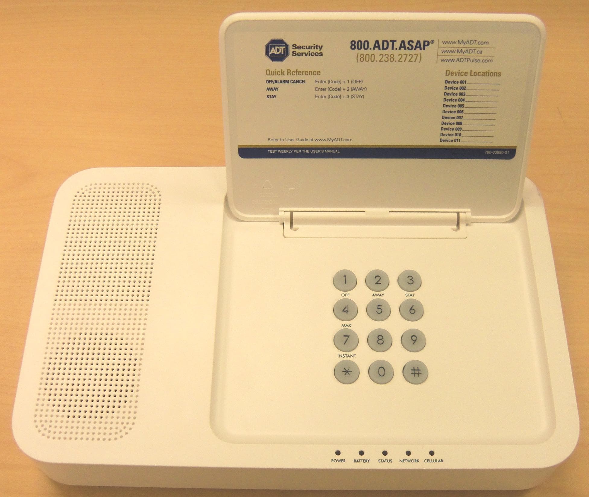
Click to zoom
Application Details
- Equipment Class
- DSC - Part 15 Security/Remote Control Transmitter
- Date of Grant
- Apr 12, 2014
- Application Purpose
- Original Equipment
- Date of Application
- Apr 10, 2014
- Equipment Note
- Security Base Control Unit
- Frequency Range
- 344.94000000 - 344.94000000
- Company
- Ademco Inc.
- Country
- United States
Documents & Files
Document Text
Text extracted from the exhibit documents filed with the FCC. Open a document above to read the original.
Users Manual
TSSBU111011U Base Control Unit and TSSKP112011U Wireless Bidirectional Alpha Keypad User Guide BASE FEATURES Display The TSSBU111011U (Base) i s a w i r el ess Con t r ol U n i t t h at al l ow s y ou t o p er f or m sy st em ar m i n g an d d i sar m i n g f u n ct i on s, as w el l as t o m on i t or t h e st at u s of y ou r secu r i t y sy st em . TSSBU111 011U w/Protective Door Removed LEDs LED Off Red Amber Green Flashing Green Flashing Amber Flashing Red Alternating Flashing POWER No AC AC BATTERY (see note 1) Low Battery/ Missing Battery Charging Battery - Normal In Programming - Red STATUS Not Ready Armed System Trouble Ready Device Trouble – Can Arm Device Trouble – Cannot Arm Alarm/Alarm Memory In Programming - Off NETWORK (see note 2) Not Confi gured No Ethernet Link Link but Not Connected to Alarm Receiver Ethernet Link In Programming - Green CELLULAR Not Configured No Connection or Bad Signal Good Signal Cell but No Data SIM Error In Programming - Off NOTE 1: D u r i n g Sl eep M od e on l y t h e BATTERY LED is active. N OT E 2: T h i s L E D m ay r em ai n i n t h e A m ber st at e f or u p t o 24 H ou r s u n t i l a r ep or t i s sen t an d ack n ow l ed ged by t h e cen t r al st at i on . CFS8DLTSSCBASE / 573F-TSSCBASE EXHIBIT 7A B – 2 – KEYPAD FEATURES Display Th e TSSKP112011U (Keypad) i s a w i r el ess Key p ad t h at al l ow s y ou t o p er f or m y ou r secu r i t y sy st em functions, as w el l as t o d i sp l ay t h e st at u s of y ou r secu r i t y sy st em . TSSKP112011U w/ Protective Door Removed LEDs LED Off Red Amber Green Flashing Green Flashing Amber Flashing Red Alternating Flashing POWER Low Battery 5%/Missing Battery (when no AC) (Keypad's battery) Charging AC On Battery – Normal (no AC) Low Battery 20% (no AC) (Keypad's battery) In Programming - Red TROUBLE In Programming, No Trouble System Trouble Device Trouble STATUS Not Ready Armed Ready to Arm Alarm/Alarm Memory In Programming - Green NOTE: D u r i n g B at t er y M od e on l y t h e POWER LED is active. – 3 – KEYS A ccess t h e Base con t r ol k ey s by l i f t i n g u p t h e d oor. T h e K ey p ad k ey s ar e con t i n u ou sl y back l i t f or ease of u se. A ccess t h e Key pad keys by op en i n g t h e sw i n g-d ow n d oor. T h e K ey p ad k ey s ar e con t i n u ou sl y back l i t f or ease of u se. KEY DESCRI PTI ON OFF D i sar m s t h e bu r gl ar y p or t i on of t h e sy st em , si l en ces al ar m s an d au d i bl e t r ou bl e i n d i cat or s, an d cl ear s v i su al al ar m t r ou bl e af t er t h e p r obl em h as been cor r ect ed . AWAY Com p l et el y ar m s bot h p er i m et er an d i n t er i or bu r gl ar y p r ot ect i on by sen si n g an i n t r u d er ' s m ov em en t s t h r ou gh p r ot ect ed i n t er i or ar eas as w el l as gu ar d i n g p r ot ect ed d oor s, w i n d ow s, et c. L at e ar r i v al s can en t er t h r ou gh an en t r y d el ay zon e (en t r an ce d oor ) without causing an al ar m i f t h e sy st em i s d i sar m ed bef or e t h e en t r y d el ay t i m e ex p i r es. ST AY A r m s t h e p er i m et er bu r gl ar y p r ot ect i on , gu ar d i n g p r ot ect ed d oor s, w i n d ow s an d ot h er p er i m et er p r ot ect i on p oi n t s, an d sou n d s an al ar m i f on e i s op en ed . A l so al l ow s au t om at i c bypassi ng of cer t ai n ar eas w h i ch p er m i t s m ov em en t w i t h i n y ou r h ou se w i t h ou t cau si n g an alarm. Late arrivals can enter through an entry delay zone (en t r an ce d oor ) without cau si n g an al ar m i f t h e sy st em i s d i sar m ed bef or e t h e en t r y d el ay t i m e ex p i r es. M AX A r m s i n m an n er si m i l ar t o A W A Y m od e, bu t el i m i n at es t h e en t r y d el ay p er i od , t h u s p r ov i d i n g m ax i m u m p r ot ect i on . A n al ar m w i l l occu r i m m ed i at el y u p on op en i n g an y p r ot ect i on p oi n t , i n cl u d i n g en t r y d el ay zon es (en t r an ce d oor s). T E ST (Key p ad on l y ) - T est s t h e sy st em an d al ar m sou n d er i f d i sar m ed . BYP ASS (Key p ad on l y ) - Rem ov es i n d i v i d u al p r ot ect i on zon es f r om bei n g m on i t or ed by t h e sy st em . D i sp l ay s p r ev i ou sl y by p assed p r ot ect i on zon es. INSTANT A r m s i n m an n er si m i l ar t o ST A Y m od e, bu t t u r n s of f t h e en t r y d el ay p er i od , of f er i n g gr eat er secu r i t y w h i l e i n si d e an d n ot ex p ect i n g an y l at e ar r i v al s. A n al ar m w i l l occu r i m m ed i at el y u p on op en i n g an y p er i m et er p r ot ect i on p oi n t , i n cl u d i n g en t r y d el ay zon es. CODE (Key p ad on l y ) - A l l ow s t h e en t r y of ad d i t i on al u ser cod es t h at can be gi v en t o ot h er u ser s of t h e sy st em . CH I ME (Key p ad on l y ) - T u r n s on an d of f t h e CH I M E m od e. W h en on , an y en t r y t h r ou gh a p r ot ect ed d el ay or p er i m et er zon e w h i l e t h e sy st em i s d i sar m ed w i l l cau se a t on e t o sou n d at the Keypad(s). READY (Key p ad on l y ) - When d ep r essed p r i or t o ar m i n g t h e sy st em , t h e Keypad will display all op en p r ot ect i on zon es w i t h i n t h e Key p ad 's h om e p ar t i t i on . T h i s k ey i s al so u sed t o d i sp l ay al l zon e d escr i p t or s t h at h av e been p r ogr am m ed f or y ou r sy st em , by h ol d i n g t h e k ey d ow n f or at l east 5 secon d s. [#] (Key p ad on l y ) - Per m i t s A RM I N G of t h e sy st em w i t h ou t u se of a secu r i t y cod e (" Qu i ck Arm" , i f p r ogr am m ed ). N u m er i c k ey s 0-9 U sed t o en t er y ou r i n d i v i d u al secu r i t y access cod e(s). Sp eci al function k ey s Pani c al ar m activ at i on (K ey p ad on l y ). The pani c al ar ms ar e act i vat ed by pr essi ng a Sp eci al F u n ct i on K ey (see bel ow ). Pan i c k ey f u n ct i on al i t y an d t h e t y p e of p an i c al ar m s p r od u ced , i s d et er m i n ed by t h e con t r ol p a…
Text truncated - open the document above for the full version.
Users Manual
1 TSSC Installation and Setup Guide STEP 1 - Installing the Base (TSSBU111011U) Recharge able Backup Battery and Power Connector 1 . Remove the Base Case Back. 2. Connect the battery connector to the receptacle on the PC board.3. Insert the Battery Pack into the case.4. Secure the Battery Pack with the Battery Retainer using the Retaining Screw.5. Connect the power pack into the power receptacle, looping the power cord as shown in Detail A. NOTE: If using the optional wall mount configuration, skip to the Base wall mounting procedure. If not, complete step 6. 6. Secure the Case Back onto the Base.NOTE: Do not apply power at this time. CASE BACK RETAINING SCREW BASE UNIT BATTERY RETAINER BATTERY PACK tssc-016-V0 DETAIL A Mounting the Base to a Wall (Optional) To mount the Base to a wall, perform to the following: IMPORTANT: Record the ACTIVATION KEY number, MAC Address, CRC number and WPA2 number located on case back prior to wall mounting. 1. Complete steps 1 through 5 of the I nstalling the Base Rechargeable Backup Battery and Power Connector paragraph 2. Secure the Mounting Plate to the wall and secure with 4 screws.3. Install the Tamper Screw as shown.4. Secure the Base to the Mounting Plate by aligning the slots on the Base and sliding the unit down until locked in position. tssc-015-V0 ENGAGE HOOKS AND SLIDE DOWN (4) WALL MOUNTING PLATE WALL SURFACE REAR OF BASE UNIT SECURE CASE BACK USING MOUNTING SCREWS (TYP - 4 PLACES) TAMPER SCREW BATTERY PACK STEP 2 - Setting up the Communication Links Prior to power up of the Base (when directed in the TSSC Installer App), the Ethernet communications link must be connected to the residence’s router. The connection is from an Ethernet port on the router to the “ETH0” port on the Base. IMPORTANT! Under no circumstances should the “ETH1” port ever be connected to the residence’s router. tssc-021-V0 BASE UNIT TO/FROM RESIDENCE ROUTER ETHERNET PORT FOR INSTALLER USE ONLY TO POWER RECEPTACLE ETH0 ETH1 STEP 3 - Keypad (TSSKP112011U) Mounting The keypad is designed to be placed on a desk/table top with the stand attached. An optional mounting plate can be used to mount the keypad to the wall. Power Connections Connect the Power Supply Cable into its connector as shown below and route it from the bottom of the keypad. IMPORTANT : Do not apply power to the keypad at this time. Installing Keypad To Desk-Top Stand 1. Place the Keypad face down on a level surface.2. Connect the battery connector to the receptacle on the PC board.3. Insert the Battery Pack into the case.4. Secure the Battery Pack with the Battery Retainer using the Retaining Screw.5. Install tabs on Desk Stand into appropriate slots as shown and secure with two screws 6 . Plug in the power pack to the receptacle. BATTERY PACK POWER SUPPLY CABLE KEYPAD tssc-011-V1 SLIDE TABS UP INTO SLOTS SLOT (TYP) DESK STAND SECURE WITH SCREWS (2) (TYP) S TEP 4 - Base Registration and Accessing The Installer App Run TSSC Installer App: Go to https://portal-test.adtpulse.com/activation and follow the prompts . Powering the Base When directed in the TSSC Installer App, plug the power pack into the wall receptacle to power the Base. During the first 45 seconds of power initialization, TSSC lights up the CELLULAR, NETWORK and STATUS LEDs one by one slowly in sequence. After the first 45 seconds, the LEDs chase in a rapid sequence for approximately 30 more seconds. The POWER LED is always ON while initialization is being executed. When the LEDs stop chasing and the POWER LED is lit green, the Base is powered up and ready for the registration process to begin. NOTE: The BATTERY LED will blink until the battery is fully charged. NOTE: The NETWORK LED will remain amber until activated. Radio Activation Go to https://portal-test.adtpulse.com/activation and follow the prompts . Ê800-13956V1oŠ 800-13956V1 11/13 Rev. A EXHIBIT 7B CFS8DLTSSCBASE / 573F-TSSCBASE 2 Contacting Technical Support PLEASE, before you call Technical Support, be sure you: READ THE INSTRUCTIONS! • Determine that the power supply and/or backup battery are supplyingproper voltages. • Verify your programming information where applicable. • Note the proper model number of this product, and the version level (ifknown) along with any documentation that came with the product. • Note your ADT customer number and/or company name. Having this information handy will make it easier for us to serve you quickly and effectively. Technical Support: Contact your ADT Customer Care Representative. THE LIMITATIONS OF THIS ALARM SYSTEM While this system is an advanced design security system, it does not offer guaranteed protection against burglary or fire or other emergency. Any alarm system, whether commercial or residential, is subject to compromise or failure to warn for a variety of reasons. For example: • Intruders may gain access through unprotected openings or have the technical sophistication to bypass an alarm sensor or disconnect an alarm warning device. • Intrusion detectors (e.g., passive infrared detectors), smoke detectors, and many other sensing devices will not work without power. Battery-operated devices will not work without batteries, with dead batteries, or if the batteries are not put in properly. Devices powered solely by AC will not work if their AC power supply is cut off for any reason, however briefly. • Signals sent by wireless transmitters may be blocked or reflected by metal before they reach the alarm receiver. Even if the signal path has been recently checked during a weekly test, blockage can occur if a metal object is moved into the path. • A user may not be able to reach a panic or emergency button quickly enough. • While smoke detectors have played a key role in reducing residential fire deaths in the United States, they may not activate or provide early warning for a variety of reasons in as many as 35% of all fires, according to data published by the Federal Emergency Management Agency. Some of the reasons smoke detectors used in…
Text truncated - open the document above for the full version.
External Photos
EXHIBIT 4-1 CFS8DLTSSCBASE / 573F-TSSCBASE Page 1 of 4 TSSCBASE EXTERNAL PHOTOS PLASTIC CASE FRONT: CLOSED EXHIBIT 4-1 CFS8DLTSSCBASE / 573F-TSSCBASE Page 2 of 4 TSSCBASE EXTERNAL PHOTOS CONT. PLASTIC CASE FRONT CONT. OPEN EXHIBIT 4-1 CFS8DLTSSCBASE / 573F-TSSCBASE Page 3 of 4 TSSCBASE EXTERNAL PHOTOS CONT. PLASTIC CASE EDGE: PLASTIC CASE BACK: WALL PLATE ATTACHED EXHIBIT 4-1 CFS8DLTSSCBASE / 573F-TSSCBASE Page 4 of 4 TSSCBASE EXTERNAL PHOTOS CONT. PLASTIC CASE BACK: WALL PLATE REMOVED
ID Label/Location Info
EXHIBIT 8 CFS8DLTSSCBASE / 573F-TSSCBASE LABEL INFORMATION EXACT LOCATION OF THE LABEL: CASE BACK ENGINEER'S DRAWING OF THE LABEL: Page 1 of 1
Internal Photos
EXHIBIT 4-2A CFS8DLTSSCBASE / 573F-TSSCBASE TSSCBASE INTERNAL PHOTOS PLASTIC CASE FRONT WITH MAIN BOARD: Page 1 of 5 EXHIBIT 4-2A CFS8DLTSSCBASE / 573F-TSSCBASE TSSCBASE INTERNAL PHOTOS CONT. PLASTIC CASE FRONT, MAIN BOARD REMOVED TOUCHPAD PCB, FRONT AND BACK: Page 2 of 5 EXHIBIT 4-2A CFS8DLTSSCBASE / 573F-TSSCBASE TSSCBASE INTERNAL PHOTOS CONT. PLASTIC CASE FRONT, TOUCHPAD PCB REMOVED: TOUCHPAD FRONT AND BACK: Page 3 of 5 EXHIBIT 4-2A CFS8DLTSSCBASE / 573F-TSSCBASE TSSCBASE INTERNAL PHOTOS CONT. MAIN BOARD, TOP Page 4 of 5 EXHIBIT 4-2A CFS8DLTSSCBASE / 573F-TSSCBASE TSSCBASE INTERNAL PHOTOS CONT. MAIN BOARD, BOTTOM Page 5 of 5
Test Report
EXHIBIT 5-1 CFS8DLTSSCBASE / 573F-TSSCBASE REPORT OF MEASUREMENTS Measurements for the Intentional Radiator,and OBW were made in accordance with the procedures and reporting requirements at: Honeywell's OATS ( FCC No: 152762 & IC No:573F-1 which is located at: 2 Corporate Center Drive, Melville, NY 11747 Measurements were made in accordance with the procedure and reporting requirements of ANSI C63.4- 2003. The Test Set-Up (C63.4 section 10.1.3) is shown in EXHIBIT 5-2: "Test Setup Photos". The sequence of testing (C63.4 section 10.1.7) for radiated emissions is as follows: A preliminary scan was conducted with the receiver antenna close to the EUT in order to identify the emission characteristics of the EUT (C63.4 section 8.3.1.1). The antenna and EUT were then placed at the proper separation ( 3 Meters) with the EUT positioned at 80 cm on a non-conducting turntable. The EUT was rotated on the turntable to maximize the received signal strength, then the receiver antenna height was varied between one (1) and four (4) Meters to further maximize the received reading. Thereafter, the device was again rotated to a peak output position and the antenna height was re-adjusted for maximum received signal. This procedure was re-iterated until there was no further increase in signal level. This procedure was performed with the EUT rotating in three orthogonal planes (C63.4 section 13.1.4.1) to generate a final maximum reading which is recorded on the radiated emissions result sheet. Similar measurements were made on the receiver to ensure compliance as an unintentional radiator. Note: The Spectrum Analyzer resolution bandwidths were set as follows: (Video Bandwidth is always set 3X greater than RBW) For Z-Wave occupied bandwidth measurements (EXHIBIT 5-4A), RBW = 100KHz and VBW = 300KHz. For Short Range Radio occupied bandwidth measurements, RBW = 30KHz and VBW = 100KHz. For radiated emissions below 1 GHz, the RBW = 100KHz. Detector function set to peak. For radiated emissions above 1GHz, the RBW = 1MHz. Detector function set to peak. TRANSMITTER RADIATED EMISSIONS are recorded in "EXHIBIT 5-3 A" and EXHIBIT 5- 3B". OCCUPIED BANDWIDTH is recorded in "EXHIBIT 5-4 A" and "EXHIBIT 5-4B". TEST EQUIPMENT (per C634. section 10.1.4) is recorded in "EXHIBIT 6". Page 1 of 1
Test Report
EXHIBIT 5-3A B CFS8DLTSSCBASE / 573F-TSSCBASE SHORT RANGE RADIO RADIATED EMISSIONS NOTE: THE SHORT RANGE RADIO WAS OPERATED IN "DIVERSITY MODE" FOR THIS TEST, AND THE SPECTRUM ANALYZER WAS SET TO MAX HOLD. THUS THIS DATA INDICATES THE WORST CASE FOR BOTH ANTENNAS. Page 1 of 1
Test Report
EXHIBIT 5-4A CFS8DLTSSCBASE / 573F-TSSCBASE SHORT RANGE RADIO (SRR) OCCUPIED BANDWIDTH RBW = 30KHz VBW = 100KHz OBW = 176.353KHz Page 1 of 1
Test Report
EXHIBIT 5-5A CFS8DLTSSCBASE / 573F-TSSCBASE TSSCBASE - CLASS B RADIATED EMISSIONS The TSS Base contains a receiver (unintentional radiator). A check for radiated emissions is done to verify the level of radiation is insignificant. An emission was found at 375.039 during initial testing. A retest at the OATS site did not discover this emission (see additional chart) INITIAL TESTING Page 1 of 6 EXHIBIT 5-5A CFS8DLTSSCBASE / 573F-TSSCBASE TSSCBASE - CLASS B RADIATED EMISSIONS CONT. INITIAL TESTING CONT. Page 2 of 6 EXHIBIT 5-5A CFS8DLTSSCBASE / 573F-TSSCBASE TSSCBASE - CLASS B RADIATED EMISSIONS CONT. INITIAL TESTING CONT. Page 3 of 6 EXHIBIT 5-5A CFS8DLTSSCBASE / 573F-TSSCBASE TSSCBASE - CLASS B RADIATED EMISSIONS CONT. RETESTING AT OATS SITE A second test on the OATS found the emission at 375.039 MHz below the limit. Page 4 of 6 EXHIBIT 5-5A CFS8DLTSSCBASE / 573F-TSSCBASE TSSCBASE - CLASS B RADIATED EMISSIONS CONT. RETESTING AT OATS SITE CONT. Page 5 of 6 EXHIBIT 5-5A CFS8DLTSSCBASE / 573F-TSSCBASE TSSCBASE - CLASS B RADIATED EMISSIONS CONT. RETESTING AT OATS SITE CONT. Page 6 of 6
Test Report
EXHIBIT 5-6 CFS8DLTSSCBASE / 573F-TSSCBASE TSSCBASE CLASS B CONDUCTED EMISSIONS LINE 1 (PHASE): Page 1 of 4 EXHIBIT 5-6 CFS8DLTSSCBASE / 573F-TSSCBASE TSSCBASE CLASS B CONDUCTED EMISSIONS CONT. LINE 1 (PHASE) CONT.: Page 2 of 4 EXHIBIT 5-6 CFS8DLTSSCBASE / 573F-TSSCBASE TSSCBASE CLASS B CONDUCTED EMISSIONS CONT. LINE 2 (NEUTRAL): Page 3 of 4 EXHIBIT 5-6 CFS8DLTSSCBASE / 573F-TSSCBASE TSSCBASE CLASS B CONDUCTED EMISSIONS CONT. LINE 2 (NEUTRAL) CONT.: Page 4 of 4
Test Report
EXHIBIT 6A CFS8DLTSSCBASE / 573F-TSSCBASE TSSCBASE TEST EQUIPMENT USED Part 15.231, ANSI C63.4, RSS 210 This is a list of all test equipment used. Note: Calibration Certificates are on following pages. Test Equipment list for Honeywell OATS & Conducted Line EQUIPMENT: MANUFACTURER: MODEL: CAL DATE: CAL DUE DATE: Spectrum Analyzer Rohde & Schwarz FSEA-20 05/09/2013 05/09/2014 Spectrum Analyzer Rohde & Schwarz FSU26 05/09/2013 05/09/2014 Spectrum Analyzer Rohde & Schwarz FSU3 05/09/2013 05/09/2014 Antenna ('Biconilog') ETS (EMCO)Lindgren 3149 07/08/2013 07/08/2014 LISN COM-POWER LI-115 10/17/2013 10/17/2014 Horn Antenna Electro-Metrics RGA 60 SN 3127 05/17/2013 05/17/2014 Low Loss Coax MEGA PHASE DC24GHz CAL BEFORE USE LNA MITEQ AFS42 CAL BEFORE USE High Pass Filter Mini-Circuits UHF-1300 CAL BEFORE USE High Pass Filter Mini-Circuits UHF-3100 CAL BEFORE USE If you need any additional information from Honeywell, please contact: Andrew Roussin, Engineer (Acting for Mark Schmidt) Phone (Direct): 516-577-5935 Email: [email protected] Page 1 of 1 jtl#,$,,S #il1iffi|$lllllrillfl,Wttr;r GENERAL CALIBRATION. INC. 2 MARS COURT 01867s General Calibration, Inc. 2 Mars Court, Boonton, New Jersey 07005 Phone (973) 299-2950 Far (973) 299-0s95 MELVILLE NY 11747 .fffi ,9 riliiiiiiriill$l$,t'ry#$l#=ryjrri Asset Tag No.: 10506 / i::;1i;;.1! :'tli : i ..:j{riwzii::':|; ;''1ffiii.,. I Certificate #: GC49-10325 ,ro Work Order #: GC49 -135 '{ Customer #: 001464 tr*ffi$til$ iiffi; ')WWllWll[Wffii*f'ffiffi HONEYWELL SECURTTY (c0t464) 2 CORPORATE CENTER DRTVE BOONTON, NJ O7OO5 R&S -\{gnufactry91 Description: SP.EW ALARMNET M"_od_e_l-]-l.I_umbgr; Serial Number: FPE44 DEN4N I-qgnected e_y: I"sh rrlle _Q_alibratjgn Resgltl Cal. Due Date: METROLOGIST MR1 " :2:9" --Q,.-!- -41 3 "o/o " _12_ "_ MolJTlq r0lr4l20r3 Condition: Found In Tolerance and Left In Tolerance 8ffi:if:,Hl ::ft+'\ :;:;?4r , ,HF 4S Il ,rl:i:, ffi...*;i ,,ht#.. riti lffi u\ tl/0t/2013 GENERAL CALIBRATION IO17 ATTENUATOR t0l7 GENERAL CALIBRATION 1039 FUNCTION GENERATOR GENERAL CALIBRATION I1O3 POWER METER 284*7A.09*6y * 3048u03!12_ 9cN?"9"0100126 2201At2339 04!rLtzlr4 L0_lr8_12-0r3 06!03!20!4 0t/t6t20r4 GEN9"*+_!"9ALrB_RArI9I i32 _ FREQUEIICY _c*-grrNJE$ GENERAL CALIBRATION 418 DIGITAL MULTIMETER GENERAL CALIBRATION 588 ATTENUATOR 2522440468 07/19/2014 GENERALCALIBRATION 636 SYNTHESZEDSWEEPEP*z6GTIZ GENERAL CALIBRATION 650 POWER SPLITTER 2120^0+._9.!- 51530 :41!2!?0!4 0ur4l20r4 Thi!i!tocerti&thatGacralcalibrrtion'Inc'isacdcdit€dbyA2LA€tdthatibcalibntidsy5tdi5in6plimc€withIso,Ecl7025.2005'ANsINcsLz540.l'ANsINcsLz540'3'dno 9o012008'Thete9tlinit!statedi!ttcr.porlcorrcsp6ddtothcManuhctur€.bcalibr*[email protected]€quipmd(rtttepointstest.d'Totheb€of{dbh oblain€d3nd8'Qortcdwa!a.curateatttcti6cofca]ibration,MEryhctorsbey@dth.6trolofGd-cdMyafdtt.pcrfmancGof.quipmdtrf.rlhcodibntid(wmdtid)mtll.bmat' cdibratimofstand,rd!;rcf€rfcesta!dard!,!dint6medirtest,ndatdsinthiscalibratimhaEbdcIEk€d4dcdibEt.dag5iEtth.tbov.wdki!gst4ddd(5) mca!ur€d€ntt[roughNation,rInstitutcofst,ndardsandTccholos,oroth€rNatio!alMea!urdn6tI!sfitut6und6mMMRA'[email protected] derot€d with A2LA acoredited lyobot on th€ calibrdion cstifcrre. tfthe Acor€dit€d cedifcate inchdes aly uaca.dihd ircG €librah4 dEy e cl€atv ns*.d B.st Unertailti.s rc?rcsert cxpand.d uncertainti€s exp!.ssed rt appro)dmately ttc 95% Mffda@ lod usitrg s cl)v@g. frdor of IF2. Thc ..sults dlFudt d itr thtu c.rtifi€t rclar. dly to th. itcn{s) crlibhtcd tr t6t d. Approved By ,&:i,.I.,,.,..' ,&;. *h/)tin.'. - - General Calibration, Inc. - Q. A. Manager lssue Date: 5ll3l20l3 GENERAL CALIBRATION. INC. 2MARS COURT General Calibration, Inc. 2 Mars Court, Boonton, New Jersey 07005 Phone (97 3) 299 -2950 F ax (97 3) 299-0595 Certificate #: 1034725 WorkOrder#: RH509 Customer#: 001464 $ffi HONEYWELL SECURTTY (001464) 2 CORPORATE CENTER DRIVE MEL\IILLE.NY I1747 BOONTON.NJ 07005 Job No.: wl7 Asset Tas No.: n4% "![gn3-fpcJuL91; Description: R&S SPECTRLIMANALYNR \4qSsl"Ny-rn!-"-r," SerialNumber: 100303 RHl FSU26 ,?qlg:!p.*1: Inspected By: Ten-p,AIIi C-p-!,fnJerv{1 Cal Date: 22.0 C I 53.0% 12 MONTHS Job Title: METROLOGIST Calibration Result: PASSED 05t09t2013 GENERAL CALIBRATION 335 SYNTHESIZED SWEEPER. 5OGTZ 3614400157 GENERALCALIBRATION 676 LEVEL GENERATOR 2516404043 9t{9?/-?9"'1" 05t2U2013 GENERAL CALIBRATION 856FREQUENCY COTINTER 51002-5 06t28t2013 GENERAL CALIBRATION 874POWERSENSOR 3318A1597 r t0n8t2013 GENERALCALIBRATION 974 POWERMETER 2709A29063 06t04t2013 This is to certi$/ that General Calibration, Inc. is A2LA accredited and that its calibration system is in compliance with ISO/IEC17025-2005, ANSI NCSLZS4O-|, ANSI NCSL 2540-3, and ISO 9001 :2008. The test limits stated in the repoqt conespond to the Manufacturer calibration and published specifications of the equipment, at the points tested. Calibrationofstandards;referencestandardsandintermediatestandardsinthiscalibrationhavebeencheckedandcalibratedagainsttheaboveworkingstandard traceable to the National Institute of Standards and Technology. Any accredited calibration under our A2LA scope of accreditation is denoted with 42LA accredited symbol on the calibration certificate. Ifthe certificate includes any unaccredited items calibrated, they are clearly marked as unaccredited calibration. Best Uncertainties represent expanded.uncertainties expressed at approximately the 95% confidence level using a coverage factor ofk=2. The results documented in this certificate relate only to the jtem(s) calibrated or tested. Approved By ".d14.- .,-. "x1 ;i:z;,',n--.:....*' General Calibration, Inc. - Q. A. Manager Issue Date: 5/13lztl3 Description: ': . .l- t' SPECTRUM ANALYZER 2 Mars Court, Boonton, New Jersey 07005 Phone (973)299-2950 Fax (973) 299-0595 6i,1,,,' '.; 1.. Certificate #z 1034723 Work Order #: RH509 Customer #: 001464 ,,riiffi$' liffii'ti. ';$ '',;1,l,;;ii;'iiii'tffi;;ili:lil GENERAL CALIBRATION" INC. 2 MARS COURT BOONTON. NJ O7OO5 'iW …
Text truncated - open the document above for the full version.
Test Report
ELECTRO.METRICS CERTIFICATE # 21651 DATE: 05/1712013 E I/E (CTXRO) -rltrE TEI.I(C S G>EE3TIFI(C - tfE (OF ([)(ON[F(O)IRIUr - \I'(CE MODEL: RGA-60 Double Ridsed Guide Antenna SERIAL # 3127 tD# 02973 CUSTOMER: HONEYWELL SECUzuTY ADDRESS: 2 CORPORATE CENTER DRIVE, MELVILLE, NY 11747 P.O.# 5959111 LINE: 1 The above equipment has been calibrated and is within the manufacturer's published limit of error. Calibration is traceable to the National Institute of Standards & Technology. Calibration has been accomplished on the above-named instrument by comparison with some or all of the following standards that are maintained by Electro-Metrics or by an authorized facility. This certificate shall not be altered or reproduced, except in full, without written approval of Electro- Metrics. o CONDITION OF EQUIPMENT RECEIVED: Non-Operational (RE: Repair Letter) o DATE CALIBRATED: 05lI7lI3 o CALIBRATION RANGE/DISTANCE: I GHz to 18 GHzl3 Meter (As per customer request). o CALIBRATION ORIENTATION: Horizontal/Vertical (As per customer request). o ENVIRONMENTAL CONDITIONS: TEMPERATURE 52 Desrees F HUMIDITY 59% o CALIBRATIONPROCEDURE: TS-J800-MOD o CALIBRATION DUE DATE: 05lI7ll4 o CALIBRATION STANDARDS: ARP958A o COMMENTS/REMARI(S: Refer to repair letter for problems/solutions. TYPE DESCRIPTION TRACEASSET# FREQUENCY A.C./D.C. RF AMPLITUDE ATTENUATION IMPULSE POWER POWER POWER EIP 371 Frequency Counter Keithley 195 System DMM Boonton 9200A RF Millivoltmeter JFW Model 50R-079 Attenuator Electro-Metrics CIG-25 HP 4358 Powermeter HP 84844 Sensor HP 8485A Sensor 13H34 B#2476 13H35 8#0093 8P673 B#0246 280687 8#0405 8rU268663-03 B#2772 5194746 B#0077 sr6|373 8#0078 5175560 8#0114 204709 9#2790 ENVIRONMENTAL Lufft Model HTAB169B Hygrometer Certified by: 231 Enterprise Road, Johnstown, New York 12095 EMAIL: [email protected] Phone: (518\762-2600 Fax: (518) 762-2812 WEB: http ://www.electro-metrics.com Page I Of I SERIAL NUMBER 3127 ELECTRO-METRICS GAIN AND ANTENNA FACTORS RGA-60 J METER CALIBRATION HORIZONTAL FREQUENCY MHZ ANTENNA FACTOR dBim GAIN dBi GAIN NUMERIC 1 000 1 500 2000 2500 3000 3500 4000 4500 5000 5500 6000 6500 7000 7500 8000 8500 9000 9500 1 0000 1 0500 11000 11500 1 2000 1 2500 1 3000 1 3500 14000 1 4500 1 5000 1 5500 1 6000 1 6500 1 7000 1 7500 1 8000 22.79 22.88 25.19 26.88 28.56 30.07 30.75 31.02 32.36 33.31 33.67 34.49 35.47 36.16 36.60 36.36 50.60 J/. to 37.50 38.01 38.54 39.25 39.55 39.68 44.24 40.65 41.23 41.40 41.23 41.04 +z.zY 42.48 41.35 43.29 44.35 7,45 10.89 11.07 11.33 11.23 11.06 11.54 12.29 11.87 11.74 12.14 12.01 11.68 11.58 11.71 12.47 12.47 12.64 12.75 12.66 12.53 12.21 12.28 12.s1 12.29 12.20 11.94 12.08 12.54 13.02 12.04 12.52 13.50 11.82 11.00 5.56 12.27 12.80 13.57 13.28 12.76 14.25 16.94 15.37 14.93 16.38 15.89 14.73 14.40 14.82 17.67 17.66 18.38 18.82 18.45 17.91 16.65 16.92 17.81 16.93 16.60 15.64 16.1 3 17.94 20.02 15.99 17.85 22.40 15.20 12.60 SPECTFTCATTON COMPLIANCE TESTTNG FACTOR (3 METER SPACTNG) TO BE ADDED TO RECEIVER METER READING lN dBuV TO CONVERT TO FIELD INTENSITY lN dBuV/METER. CALIBRATION PER ARP 958 METHODOLOGY. SERIAL NUMBER 3127 ELECTRO-METRICS GAIN AND ANTENNA FACTORS RGA-60 3 METER GALIBRATION VERTICAL FREQUENCY MHZ ANTENNA FACTOR dB/m GAIN dBi GAIN NUMERIC 1 000 1 500 2000 2500 3000 3500 4000 4500 5000 5500 6000 6500 7000 7500 8000 8500 9000 9500 1 0000 1 0500 11000 11500 1 2000 12500 1 3000 1 3500 1 4000 14500 1 5000 1 5500 16000 1 6500 1 7000 1 7500 1 8000 21.34 23.29 25.94 27.59 28.67 29.98 30.91 30.93 32.00 33.10 33.31 34.04 35.23 36.08 36.31 36.40 36.62 36.95 37.47 38.03 38.51 39.00 39.17 39.27 39.84 40.58 40.81 41.27 40.89 40.06 40.26 40.90 42.41 45.13 44.96 8.90 10.48 10.32 10.62 11.12 11.15 11.38 12.38 12.22 11.95 12.50 12.47 11.92 11.66 12.00 12.43 12.71 12.85 12.78 12.64 12.56 12.46 12.66 12.91 12.69 12.28 12.36 12.21 12.88 13.99 14.A7 13.70 12.45 9.98 10.39 7.77 11.18 10.77 11.53 12.95 13.04 13.73 17.30 16.68 15.67 17.84 17.65 15.55 14.66 15.84 17,50 18.66 19.27 18.95 18.38 18.03 17.64 18.47 19.55 18.56 16.89 17.21 16.62 19.40 25.06 25.55 23.43 17.57 oo4 10.95 SPEC|FTCATTON COMPLIANCE TESTING FACTOR (3 METER SPACTNG) TO BE ADDED TO RECEIVER METER READING lN dBuV TO CONVERT TO FIELD INTENSITY IN dBuV/METER. CALIBRATION PER ARP 958 METHODOLOGY. ELECTRO.METRICS INC. 23I Enterprise Road Johnstown, NY 12095 Telephone No. (518) 762-2600 FaxNo. (518)762-2812 DATE: 0511712013 CUSTOMER: Honeywell Security ATTENTION: Gregory Barbato 2 Corporate Center Drive Melville,NY 11747 Dear Customer, In accordance with Electro-Metrics policy, you are hereby notified that the following listed equipment was Non-Operational when received for Calibration: Manufacturer: Model Number: Serial Number: Company ID: Description: P.O. Number: Electro-Metrics RGA-60 3r27 02973 Ridge Guide Horn Antenna 595111 The Non-Operational condition(s) were as follows: 1) The antenna did not appear to be operating over its stated frequency range, no or very low signal outputs were noted. The Action(s) taken to correct the Non-Operational condition(s) were as follows: 1) The problem was traced to the VSWR being significantly out of tolerance. When readjustment was attempted to correct tolerance, it was noted that the adjusting pin was very loose within the feed block. Upon further investigation, it was found that the threads within the feed block had deteriorated. The lower feed block was replaced, VSWR was adjusted to within specification limits. The unit was then calibrated at 3 Meter, horizontal and vertical (as per customer request); the data indicated all readings within specification limits. | /,t A 1,1/ ft // | Calibration Technicran (Page I of !) QA FORM #r0r Rev 1.5 12107199
Contact Information
Applicant
Christian Fouth(Sr. Wireless Certification Engineer)
Technical Contact
Honeywell International Inc.Stanley Albrechtsen
[email protected]516 677 5860
2 Corporate Center Drive · Melville · United States
Non-Technical Contact
Honeywell International Inc.Mark Schmidt
[email protected]516 577 5939
Test Firm
Honeywell International Inc.Mark Schmidt
Technical Specifications
| # | Rule Parts | Frequency Range | Power Output |
|---|---|---|---|
| 1 | 15.231 | 344.94 MHz - 344.94 MHz | - |
Other Applications from Ademco Inc.

CFS8DL5800MINIV
Jan 28, 2026Wireless Alarm Transmitter
Equipment Class
DXX - Part 15 Low Power Communication Device Transmitter
CFS8DLWTS800
Jan 12, 2026Wireless Alarm Transmitter
Equipment Class
DTS - Digital Transmission SystemCFS8DLCAMWEWI1
Jul 25, 2024VX5 HD Indoor Camera
Equipment Class
DTS - Digital Transmission System
CFS8DLCAMWEWO1
Sep 17, 2023VX3 HD Outdoor Camera
Equipment Class
NII - Unlicensed National Information Infrastructure TX
CFS8DLLMD500A
Jul 20, 2023Wireless door/window contact
Equipment Class
DTS - Digital Transmission System