CFS8DLTSSCKPWireless Keypad
Ademco Inc.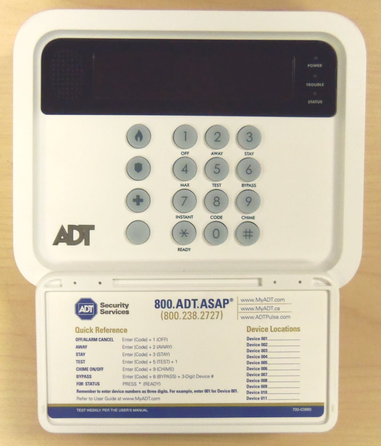
Click to zoom
Application Details
- Equipment Class
- DSR - Part 15 Remote Control/Security Device Transceiver
- Date of Grant
- Feb 12, 2014
- Application Purpose
- Original Equipment
- Date of Application
- Feb 12, 2014
- Equipment Note
- Wireless Keypad
- Frequency Range
- 344.94000000 - 344.94000000
- Company
- Ademco Inc.
- Country
- United States
Documents & Files
Document Text
Text extracted from the exhibit documents filed with the FCC. Open a document above to read the original.
Users Manual
TSSKP112011U Wireless Bidirectional Alpha Keypad INSTALLATION AND SETUP GUIDE GENERAL INFORMATION The TSSKP112011U (hereinafter the Keypad) is a wireless bidirectional alpha keypad that is used in conjunction with the TSSBU111011U (Base). The Keypad should be used as an auxiliary keypad in addition to the Base. Up to a total of eight (8) Keypads can be used on the system. ENROLLING OR DELETING ENROLLED KEYPADS The Keypads must be enrolled using the TSSC Installer App (https://portal.adtpulse.com/activation). Previously enrolled Keypads may be deleted if desired using the TSSC Installer App. PROGRAMMING SRID AND KEYPAD ID Additional Keypad(s) or replacement Keypads are added to the TSSC system as follows: 1. Remove back cover, power, and battery from Keypad. 2. Apply power and within 30 seconds hold down the 1 and 3 keys simultaneously until PROGRAM MODE is displayed. 3. If the Keypad has been previously installed on a different system, hit the # key until DEFAULT KEYPAD is displayed. Press 3 = Yes, then press the # key to accept. Repeat step 2. 4. Enter SRID xxxxx into the SRID field and press #. (The SRID is found on the back of the Base or within the Installer App). 5. Enter a unique Keypad ID (01-08) and press #. 6. Press the * key to save and exit Keypad Program Mode. KEYPAD MOUNTING The Keypad is designed to be placed on a desk/table top with the stand attached. An optional mounting plate (PN TSSKP112041U) can be used to mount the keypad to the wall. POWER CONNECTIONS The Keypad is powered from an external 110VAC input/9VDC output power pack (supplied). A 7.2VDC battery back provides 24-hour backup power. Connect the Power Supply Cable into its connector as shown below and route it from the bottom of the Keypad. IMPORTANT: Do not apply power to the Keypad at this time. INSTALLING KEYPAD TO DESK-TOP STAND 1. Place the Keypad face down on a level surface. 2. Connect the battery connector to the receptacle on the PC board. 3. Secure the Battery Pack into the case. 4. Secure the Battery Pack with the Battery Retainer using the Retaining Screw. 5. Install tabs on Desk Stand into appropriate slots as shown and secure with two screws. 6. Plug in the power pack to the receptacle. BATTERY REPLACEMENT – DESK TOP CONFIGURATION 1. Disconnect power to the Keypad. 2. Remove two screws securing the Desk Stand to the Keypad. 3. Loosen screw that secures the battery retainer and slide battery retainer upward. 4. Lift battery from battery compartment and disconnect the battery from the Keypad. 5. Connect the new battery to the keypad and place the battery in the battery compartment. 6. Slide the battery retainer down so that the battery is secured and tighten the screw. 7. Install the tabs on Desk Stand into appropriate slots and secure with two screws. 8. Connect power to the Keypad. INSTALLING WALL MOUNTED KEYPAD (OPTIONAL) 1. Secure the Wall Mounting Plate (not supplied) to the wall. 2. Connect the Power Supply Cable into its connector as shown and route it from the bottom of the Keypad. 3. Align the Keypad with the Wall Mounting Plate and slide the Keypad downward until it locks in place. 4. Secure the Keypad onto the wall mounting plate with the retaining screw. 5. Connect power to the Keypad. BATTERY REPLACEMENT – WALL MOUNTED KEYPAD 1. Disconnect power to the Keypad. 2. Remove the retaining screw at the bottom of the Keypad. 3. Press upward with your thumbs on the bottom edge of the Keypad housing and slide the Keypad up with respect to the wall mounting plate, removing the Keypad from the wall mounting plate. 4. Connect the power harness to the printed circuit board. 5. Replace the Keypad onto the wall mounting plate and secure with the retaining screw. TSSKP112011U SPECIFICATIONS: Physical: 6.69” W x 5.36” H x 0.875” D (169.78mm x 136.03mm x 22.03mm) Frequency of Operation: 345 MHz Battery Pack: P/N TSSKP112061U: 7.2V, 6xAAA, 6x600mAH, NiMH Transformer: P/N 300-05763: 110 VAC input/9 VDC output 2.5A, 2-prong LCD Display: 2x16, COG, 6V, B/W Sounder: Piezoelectric NOTE: After installing the battery and reattaching the Keypad to the mounting plate, enter 4-digit User code + OFF sequence twice to clear any trouble condition. REFER TO THE INSTALLATION INSTRUCTIONS FOR THE TSSBU111011U CONTROL WITH WHICH THIS DEVICE IS USED, FOR DETAILS ON LIMITATIONS OF THE ENTIRE ALARM SYSTEM. FEDERAL COMMUNICATIONS COMMISSION STATEMENTS The user shall not make any changes or modifications to the equipment unless authorized by the Installation Instructions or User's Manual. Unauthorized changes or modifications could void the user's authority to operate the equipment. CLASS B DIGITAL DEVICE STATEMENT This equipment has been tested to FCC requirements and has been found acceptable for use. The FCC requires the following statement for your information: This equipment generates and uses radio frequency energy and if not installed and used properly, that is, in strict accordance with the manufacturer's instructions, may cause interference to radio and television reception. It has been type tested and found to comply with the limits for a Class B computing device in accordance with the specifications in Part 15 of FCC Rules, which are designed to provide reasonable protection against such interference in a residential installation. However, there is no guarantee that interference will not occur in a particular installation. If this equipment does cause interference to radio or television reception, which can be determined by turning the equipment off and on, the user is encouraged to try to correct the interference by one or more of the following measures: • If using an indoor antenna, have a quality outdoor antenna installed. • Reorient the receiving antenna until interference is reduced or eliminated. • Move the radio or television receiver away from the receiver/control. • Move the antenna leads away from any wire runs to the receiver/control. • Plug the receiver/control into a different outlet so that it and the …
Text truncated - open the document above for the full version.
External Photos
EXHIBIT 4-1 CFS8DLTSSCKP / 573F-TSSCKP TSSCKP EXTERNAL PHOTOS PLASTIC CASE FRONT: CLOSED Page 1 of 4 EXHIBIT 4-1 CFS8DLTSSCKP / 573F-TSSCKP TSSCKP EXTERNAL PHOTOS CONT. PLASTIC CASE FRONT CONT.: OPEN Page 2 of 4 EXHIBIT 4-1 CFS8DLTSSCKP / 573F-TSSCKP TSSCKP EXTERNAL PHOTOS CONT. PLASTIC CASE BACK: Page 3 of 4 EXHIBIT 4-1 CFS8DLTSSCKP / 573F-TSSCKP TSSCKP EXTERNAL PHOTOS CONT. PLASTIC CASE BACK CONT.: Page 4 of 4
ID Label/Location Info
EXHIBIT 8 CFS8DLTSSCKP / 573F-TSSCKP LABEL INFORMATION EXACT LOCATION OF THE LABEL: CASE BACK ENGINEER'S DRAWING OF THE LABEL: Page 1 of 1
Internal Photos
EXHIBIT 4-2 CFS8DLTSSCKP / 573F-TSSCKP TSSCKP INTERNAL PHOTOS PLASTIC CASE FRONT (SHIELDS ATTACHED): Note - of the three shields, the lower left shield is never populated on this assembly. Page 1 of 8 EXHIBIT 4-2 CFS8DLTSSCKP / 573F-TSSCKP TSSCKP INTERNAL PHOTOS CONT. PLASTIC CASE FRONT (SHIELDS REMOVED): Page 2 of 8 EXHIBIT 4-2 CFS8DLTSSCKP / 573F-TSSCKP TSSCKP INTERNAL PHOTOS CONT. PLASTIC CASE FRONT MINUS PCB: Page 3 of 8 EXHIBIT 4-2 CFS8DLTSSCKP / 573F-TSSCKP TSSCKP INTERNAL PHOTOS CONT. PLASTIC CASE FRONT MINUS PCB AND KEYPAD MEMBRANE: KEYPAD MEMBRANE Page 4 of 8 EXHIBIT 4-2 CFS8DLTSSCKP / 573F-TSSCKP TSSCKP INTERNAL PHOTOS CONT. PLASTIC CASE BACK: Page 5 of 8 EXHIBIT 4-2 CFS8DLTSSCKP / 573F-TSSCKP TSSCKP INTERNAL PHOTOS CONT. PCB FRONT AND LCD: Page 6 of 8 EXHIBIT 4-2 CFS8DLTSSCKP / 573F-TSSCKP TSSCKP INTERNAL PHOTOS CONT. PCB BACK AND LCD (SHIELDS INSTALLED): Note - of the three shields, the lower left shield is never populated on this assembly. Page 7 of 8 EXHIBIT 4-2 CFS8DLTSSCKP / 573F-TSSCKP TSSCKP INTERNAL PHOTOS CONT. PCB BACK (SHIELDS REMOVED): Page 8 of 8
Test Report
EXHIBIT 5-1 CFS8DLTSSCKP / 573F-TSSCKP REPORT OF MEASUREMENTS Measurements for the Intentional Radiator,and OBW were made in accordance with the procedures and reporting requirements at: Honeywell's OATS ( FCC No: 152762 & IC No:573F-1 which is located at: 2 Corporate Center Drive, Melville, NY 11747 Measurements were made in accordance with the procedure and reporting requirements of ANSI C63.4- 2003. The Test Set-Up (C63.4 section 10.1.3) is shown in EXHIBIT 5-2: "Test Setup Photos". The sequence of testing (C63.4 section 10.1.7) for radiated emissions is as follows: A preliminary scan was conducted with the receiver antenna close to the EUT in order to identify the emission characteristics of the EUT (C63.4 section 8.3.1.1). The antenna and EUT were then placed at the proper separation ( 3 Meters) with the EUT positioned at 80 cm on a non-conducting turntable. The EUT was rotated on the turntable to maximize the received signal strength, then the receiver antenna height was varied between one (1) and four (4) Meters to further maximize the received reading. Thereafter, the device was again rotated to a peak output position and the antenna height was re-adjusted for maximum received signal. This procedure was re-iterated until there was no further increase in signal level. This procedure was performed with the EUT rotating in three orthogonal planes (C63.4 section 13.1.4.1) to generate a final maximum reading which is recorded on the radiated emissions result sheet. Similar measurements were made on the receiver to ensure compliance as an unintentional radiator. Note: The Spectrum Analyzer resolution bandwidths were set as follows: (Video Bandwidth is always set 3X greater than RBW) For occupied bandwidth measurements, RBW = 30KHz and VBW = 100KHz. For radiated emissions below 1 GHz, the RBW = 100KHz. Detector function set to peak. For radiated emissions above 1GHz, the RBW = 1MHz. Detector function set to peak. TRANSMITTER RADIATED EMISSIONS are recorded in "EXHIBIT 5-3". OCCUPIED BANDWIDTH is recorded in "EXHIBIT 5-4". TEST EQUIPMENT (per C634. section 10.1.4) is recorded in "EXHIBIT 6". Page 1 of 1
Test Report
EXHIBIT 5-3 CFS8DLTSSCKP / 573F-TSSCKP RADIATED EMISSIONS Page 1 of 1
Test Report
EXHIBIT 5-4 CFS8DLTSSCKP / 573F-TSSCKP OCCUPIED BANDWIDTH RBW = 30KHz VBW = 100KHz OBW = 180.361 KHz (OBW limit = 862.35KHz @344.940 MHz) Page 1 of 1
Test Report
EXHIBIT 5-5 CFS8DLTSSCKP / 573F-TSSCKP TSSCKP CLASS B RADIATED EMISSIONS
Test Report
EXHIBIT 6 CFS8DLTSSCKP / 573F-TSSCKP TEST EQUIPMENT USED FOR TSSCKP Part 15.231, ANSI C63.4, RSS 210 This is a list of all test equipment used. Note: Calibration Certificates are on following pages. Test Equipment list for Honeywell OATS & Conducted Line EQUIPMENT: MANUFACTURER: MODEL: CAL DATE: CAL DUE DATE: Spectrum Analyzer Rohde & Schwarz FSU26 05/09/2013 05/09/2014 Antenna ('Biconilog') ETS (EMCO)Lindgren 3149 07/08/2013 07/08/2014 Spectrum Analyzer Rohde & Schwarz FSU3 05/09/2013 05/09/2014 LISN COM-POWER LI-115 10/17/2013 10/17/2014 If you need any additional information from Honeywell, please contact: Andrew Roussin, Engineer (Acting for Mark Schmidt) Phone (Direct): 516-577-5935 Email: [email protected] Page 1 of 5 lssue Date: 5ll3l20l3 GENERAL CALIBRATION. INC. 2MARS COURT General Calibration, Inc. 2 Mars Court, Boonton, New Jersey 07005 Phone (97 3) 299 -2950 F ax (97 3) 299-0595 Certificate #: 1034725 WorkOrder#: RH509 Customer#: 001464 $ffi HONEYWELL SECURTTY (001464) 2 CORPORATE CENTER DRIVE MEL\IILLE.NY I1747 BOONTON.NJ 07005 Job No.: wl7 Asset Tas No.: n4% "![gn3-fpcJuL91; Description: R&S SPECTRLIMANALYNR \4qSsl"Ny-rn!-"-r," SerialNumber: 100303 RHl FSU26 ,?qlg:!p.*1: Inspected By: Ten-p,AIIi C-p-!,fnJerv{1 Cal Date: 22.0 C I 53.0% 12 MONTHS Job Title: METROLOGIST Calibration Result: PASSED 05t09t2013 GENERAL CALIBRATION 335 SYNTHESIZED SWEEPER. 5OGTZ 3614400157 GENERALCALIBRATION 676 LEVEL GENERATOR 2516404043 9t{9?/-?9"'1" 05t2U2013 GENERAL CALIBRATION 856FREQUENCY COTINTER 51002-5 06t28t2013 GENERAL CALIBRATION 874POWERSENSOR 3318A1597 r t0n8t2013 GENERALCALIBRATION 974 POWERMETER 2709A29063 06t04t2013 This is to certi$/ that General Calibration, Inc. is A2LA accredited and that its calibration system is in compliance with ISO/IEC17025-2005, ANSI NCSLZS4O-|, ANSI NCSL 2540-3, and ISO 9001 :2008. The test limits stated in the repoqt conespond to the Manufacturer calibration and published specifications of the equipment, at the points tested. Calibrationofstandards;referencestandardsandintermediatestandardsinthiscalibrationhavebeencheckedandcalibratedagainsttheaboveworkingstandard traceable to the National Institute of Standards and Technology. Any accredited calibration under our A2LA scope of accreditation is denoted with 42LA accredited symbol on the calibration certificate. Ifthe certificate includes any unaccredited items calibrated, they are clearly marked as unaccredited calibration. Best Uncertainties represent expanded.uncertainties expressed at approximately the 95% confidence level using a coverage factor ofk=2. The results documented in this certificate relate only to the jtem(s) calibrated or tested. Approved By ".d14.- .,-. "x1 ;i:z;,',n--.:....*' General Calibration, Inc. - Q. A. Manager -'", ' ,i Issue Job No.: Manufacturer: t;;;;tpil Depa-rtment: Temp/RH: -Cpt,Interval: Cal Date: ' e'glsll;': ;"1' I i:i:$ti' Date: 5/13/21t13 Certificate #z 1034723 Work Order #: RH509 Customer #:001464 * i::, iiiiillml$l,n;=1t=l-1-*€ * GENERAL CALIBRANON INC. 2 MARS COURT BOONTON, NJ O7OO5 i*s*p*ffi ;iiitrlriiiiiiriliiiiii iil,,ffi ;iiinlriil ,,iiiiiillli ,;,,,. HONEYWELL SECUR{ry (001,164) 2 CORPORATE CENTER DRTVE '583920 ir.'i.l' ' , ,,ll n493 FSU3 1000? RHl ^t PAF$-Eq 0st0:e-12p"!4 ,:.::.i::lj.'. *"o**+,,S^ ::ir. g$r _ .. _1.fi,.',. ii ':' se,liel Number . 36_!44001:J us37298428 25 r 6404043 5 I 002-5 2709429063 . l' ;li 11i..l!,.'l,' Cal. Due Date '.. 08t02t20r! 07t06t219r3 05t21t2013 06/28/2013 06t04t2013 ::::::;:.ig:j:irii:,i:i'.:.:= : : :i:. .. \ t:t:: I l 066,615 R&S srECry 22.0 C I 53.0% it-_ MoNTHS =.. 0:t09'20 _r?. ,' ffi35tt3 t"'.'*, ,,,' ' l.' MELVILLE,NY I1747 -==,1nr€ii;;Xffi;, ^tr**iiitit$ i. ... ,, Asset Tag No,; ModglNumbe-1: Serial Numbe-ri .. . Inspecled By: - Job=.T-itle:..-. C-allbptiorr-R9-sult; _ . . Cal, Dug D- ate: , "' , , l:l].:,ll;;,'i;iiidi+lllr'$-ii1. l11l.1i',,,,1 11 Condition: Found In Tolerance and Left In Tolerance ':rl ' '.''''::: G-ENERAL CALTBRATION.. 135,,. SYNTr{ESI_Z_ED SWEEPER, 50crz GENERALCALTB_RATTON_ 661 POWpRSENSOR GENERAL. CALIBRATI-OT 976 LEVEL GENERATOR GENERAL CALTBRAIIO_N 8s6 flp_aUENCy corrNrER GENERAL CALIBRATION 974 POWER METER #i\i li.\iif ::.:.::1ii iui 'Ihis is to certify that Geneml Calibration, Inc. is A2LA accredited and that ifs c€libmtion system is in compliance with ISO ECI?025-2005, AI{SI NCSL2540-t, ANSI NCSL 2540-3, and ISO 9001i2qc8. The test limits stated in the report correspond to the Manufactrr calibBtion and published specifcations ofthe equipment, at the points tested. caIibrationofstandards:r€ferencestandardsandint€rmediatestandardsinthiscalibrationhavebeerrcheckodandcalibmtedagainsttheaboYeworkingstandafd tmceable to the National Institute ofstandards and Technology. Any accredited calibration under our A2LA scope ofaccreditation is denoted with A2LA accredited s],rnbol on the calibmtion certificate. Ifthe certilicale includes any unaccredited iterns calibrated, they are clearly mart€d as unaccr€dited calibmtion. []est Uncertainties represent e4anded uncertainties expressed at approximately the 95% confidence l€v€l using a coverage factor ofl--2_ The results documented in this c€rtificat€ relate only to the item(s) calibrated or t€sted. Approved By ...;ti;.; ,n ,-.' -,{i: )./,:;{i::i,,*...,. -- General Calibration,Inc. - Q. A. Manager T'bce|[email protected]'w.J.ndkponib|efd.tlyd.nsg6rb|lingnom$eu*olth6ednd'rd3by,lo@8I'fbido
Test Report
EXHIBIT 5-6 CFS8DLTSSCKP / 573F-TSSCKP TSSCKP CLASS B LINE CONDUCTED EMISSIONS LINE 1 (PHASE) Page 1 of 2 EXHIBIT 5-6 CFS8DLTSSCKP / 573F-TSSCKP TSSCKP CLASS B LINE CONDUCTED EMISSIONS CONT. LINE 2 (NEUTRAL) Page 2 of 2
Test Setup Photos
EXHIBIT 5-2 CFS8DLTSSCKP / 573F-TSSCKP PICTURES OF THE UNIT UNDER TEST & THE OATS TEST SETUP SENSE: HORZ, UUT: VERT SENSE: HORZ , UUT: HORZ SENSE: HORZ , UUT: OBLQ. SENSE: VERT, UUT: VERT SENSE: VERT , UUT: HORZ SENSE: VERT , UUT: OBLQ. Page 1 of 4 EXHIBIT 5-2 CFS8DLTSSCKP / 573F-TSSCKP PICTURES OF THE UNIT UNDER TEST & THE OATS TEST SETUP CONT. PICTURE SHOWING UNIT AND ROTATING TABLE Note - AC power is supplied from yellow cord on bottom shelf Page 2 of 4 EXHIBIT 5-2 CFS8DLTSSCKP / 573F-TSSCKP PICTURES OF THE UNIT UNDER TEST & THE OATS TEST SETUP CONT. HONEYWELL’S 3 METER OATS AT: 2 Corporate Center Drive,Melville, NY 11747 Page 3 of 4 EXHIBIT 5-2 CFS8DLTSSCKP / 573F-TSSCKP PICTURES OF THE UNIT UNDER TEST & THE AC POWER LINE EMISSIONS TEST SETUP Page 4 of 4
Contact Information
Applicant
Christian Fouth(Sr. Wireless Certification Engineer)
Technical Contact
Honeywell International Inc.Stanley Albrechtsen
[email protected]5165775860
2 Corporate Center Drive · Melville, New York · United States
Non-Technical Contact
Honeywell International Inc.Mark Schmidt
[email protected]5165775939
Test Firm
Honeywell International Inc.Mark Schmidt
Technical Specifications
| # | Rule Parts | Frequency Range | Power Output |
|---|---|---|---|
| 1 | 15.231 | 344.94 MHz - 344.94 MHz | - |
Other Applications from Ademco Inc.

CFS8DL5800MINIV
Jan 28, 2026Wireless Alarm Transmitter
Equipment Class
DXX - Part 15 Low Power Communication Device Transmitter
CFS8DLWTS800
Jan 12, 2026Wireless Alarm Transmitter
Equipment Class
DTS - Digital Transmission SystemCFS8DLCAMWEWI1
Jul 25, 2024VX5 HD Indoor Camera
Equipment Class
DTS - Digital Transmission System
CFS8DLCAMWEWO1
Sep 17, 2023VX3 HD Outdoor Camera
Equipment Class
NII - Unlicensed National Information Infrastructure TX
CFS8DLLMD500A
Jul 20, 2023Wireless door/window contact
Equipment Class
DTS - Digital Transmission System