CGDFC180RRFAnti-Pilferage device
Nedap N. V.Application Details
- Equipment Class
- FAP - Part 15 Anti-Pilferage Device
- Date of Grant
- Jul 19, 2015
- Application Purpose
- Original Equipment
- Date of Application
- Jul 19, 2015
- Equipment Note
- Anti-Pilferage device
- Frequency Range
- 7.56500000 - 8.57125000
- Company
- Nedap N. V.
- Country
- Netherlands
Documents & Files
Document Text
Text extracted from the exhibit documents filed with the FCC. Open a document above to read the original.
Users Manual
PRELIMINARY Doorframe i7 Manual FC-line Page of 243Manual FC-line Contents 1Introduction: _________________________________________________________________________________ 4 CE WEEE __________________________________________________________________________________ 5 Battery disposal ___________________________________________________________________________ 5 2Product overview ____________________________________________________________________________ 6 Box contents ______________________________________________________________________________ 6 Components ______________________________________________________________________________ 7 Dimensions _______________________________________________________________________________ 9 Connections _____________________________________________________________________________ 10 Add-ons _________________________________________________________________________________ 11 3Preparing the installation ____________________________________________________________________ 13 Defining the system _______________________________________________________________________ 13 Field distribution for RF ____________________________________________________________________ 14 Device Management ______________________________________________________________________ 15 4Executing the installation ____________________________________________________________________ 16 Physical installation: Wall mounting _________________________________________________________ 16 Physical installation: Mount electronic unit ___________________________________________________ 20 Physical installation: Installing cabling and filters ______________________________________________ 21 Physical installation: Mount the LED PCB _____________________________________________________ 23 Physical installation: Mount the Buzzer PCB ___________________________________________________ 24 Connect Renos and Power Inserter __________________________________________________________ 25 Status LEDs on Renos unit __________________________________________________________________ 26 Place cover ______________________________________________________________________________ 27 5Configuring the installation ___________________________________________________________________ 28 Driver installation _________________________________________________________________________ 28 Recent browser ___________________________________________________________________________ 28 Connecting a laptop to the Renos unit _______________________________________________________ 29 Entering the configuration wizard ___________________________________________________________ 29 Authentication ___________________________________________________________________________ 29 Getting help in the wizard __________________________________________________________________ 30 Firmware version and System ID ____________________________________________________________ 30 Factory reset _____________________________________________________________________________ 30 Firmware change _________________________________________________________________________ 31 6Integrating the installation with other systems __________________________________________________ 33 Software integration with API's _____________________________________________________________ 33 Physical integration using an IO Box _________________________________________________________ 33 URL trigger _______________________________________________________________________________ 34 7Servicing the installation _____________________________________________________________________ 35 Nedap Device Management ________________________________________________________________ 35 Page of 343Manual FC-line SNMP ___________________________________________________________________________________ 35 8Troubleshooting ____________________________________________________________________________ 36 Physical installation _______________________________________________________________________ 36 Configuration ____________________________________________________________________________ 37 RF technology issues ______________________________________________________________________ 37 9Regulatory information ______________________________________________________________________ 40 FCC and IC Compliance statement ___________________________________________________________ 40 FCC and IC Radiation Exposure Statement ____________________________________________________ 40 FCC Information to the user ________________________________________________________________ 40 Information for Taiwan ____________________________________________________________________ 41 10About Nedap _______________________________________________________________________________ 42 About ___________________________________________________________________________________ 42 Contact __________________________________________________________________________________ 42 Page of 443Manual FC-line 1 Introduction: The Doorframe i7 is a state-of-the-art 8.2 MHz RF antenna with customer counting sensors for Intelligent Article Surveillance (IAS). The antenna can easily be mounted on a door or window frame, keeping the entrance of the store wide open. The Doorframe i7 is a concealed solution especially designed for narrow entrances and entrances where placing gates on the floor is not practical or preferred. Knowledge Base articles This manual provides an overview of the products, the installation and configuration. To obtain more details on various topics or background information, several Knowledge Base articles are available, and are referred to in this manual. You can find the Knowledge Base articles on the Nedap Retail portal. This manual covers the following products: Article numberArticle nameTechnologiesModel name 9563725ASSY FC180R RF WHITE8.2 MHz RFASSY FC180R RF 9563725ASSY FC180R RF WHITE + Metal Detection8.2 MHz RFASSY FC180R RF + MD 921656…
Text truncated - open the document above for the full version.
Users Manual
Page of 13Commercial guidelines Doorframe i7 Commercial guidelines Doorframe i7 The Doorframe i7 is a special product, please follow these commercial guidelines. By doubt contact The lead time of this product is on request. [email protected] (mailto:[email protected]) yourself in advance because the lead time might be longer than expected. The best RF system you never see! The Doorframe i7 is a concealed solution especially designed for narrow entrances and entrances where it is not preferred or practical to place gates on the floor Create more sales space! Because the detection field is closer to the exit, this also creates less false alarms by secured items moving in store Note: be aware that when there is an alarm, people causing the alarm will already be outside of the store (because it is positioned so close to the exit) Doorframe i7 has Standard integrated Customer counting Doorframe i7 is part of !Sense, Intelligent Loss Prevention. The Doorframe i7 has the option for a real-time !Sense Dashboard. A local API for integrations. Nedap Retail Analytics, to focus on increasing dwell time, managing staff efficiently, know store’s peak hours etc. Remote firmware upgrades, so the system can improve over time. Device Management for quick service to continuously keep shrinkage low Best homogeneous RF 8.2 MHz rotation detection field The preferred installation for best performance is to use 2 x i7 in ‘Focussed field’. This means that there is no detection on the outsides. Focussed field is an unique Nedap !Sense software setting that no competitor has Page of 23Commercial guidelines Doorframe i7 The preferred installation is 2 times an i7 in focussed field. The performance in focused field, with a distance between the i7 of 2 meter [6,6 feet] gives a detection chance of 90% or higher can be reached with a NT4040 label. When the distance is 2,20 meter [7 feet] a detection chance of 75% or higher can be reached with a NT4040 label It is possible to place the Doorframe i7 in ‘Full field’ and use only 1 x i7 in the middle of an entrance. Please note the Asymmetrical field of 90 cm on one side and 110 cm on the other side Page of 33Commercial guidelines Doorframe i7 The Doorframe i7 should be placed around 20/30 cm [8/12 in] from the floor The Doorframe i7 can be mounted to the wall or be placed on a Floor mount column. The Floor mount column is recommended for best performance The material of the wall or Frame of the retailer can strongly influence the RF performance. Especially when the frame is made of metal. Therefore the installation material includes distance holders (2,5 cm [0,9 in] from the frame) Optional: Metal Detection. Only possible when there are no moving doors with metal (i.e. an aluminum frame around the door) Last modification: 13 July 2015 13:27
Users Manual
The Doorframe i7 is a state-of-the-art 8.2 MHz RF antenna with customer counting sensors for intelligent article surveillance (IAS). It can easily be mounted on a door or window frame, keeping the entrance of the store wide open. The Doorframe i7 is a concealed solution especially designed for very narrow entrances and entrances where it is not preferred or practical to place gates on the floor. specifications • Equipped with Nedap’s OID (Orientation Independent Detection) technology; tags are detected regardless of their position (front/flat/ side/angled) • Acoustic and visual alarm signalization • Customer counting • Integration possibility with other (3rd party) security devices via open API • Real-time insight and control with in-store and organization-wide dashboards • Remote service • Can be mounted on wall or doorframe Doorframe i7 www.nedap-retail.com Parallelweg 2d NL-7141 DC Groenlo the Netherlands t +31 (0) 544 471555 f +31 (0) 544 465814 [email protected] ordering information DescriptionArticle number ASSY FC180R RF WHITE9563725 PS Assy FC180R RF | 15-04-2015 75mm / 3” 171mm / 6,7” 1233mm / 4ft 1781mm / 5.8ft options • Floor mount column • Real-time in-store security dashboard • Organization-wide (multi-store) dashboard via Web or App • Open API (Application Programming Interface) technical specifications • Frequency8.2 MHz • Dimensions1781mm x 171mm x 75mm 5.84ft x 6.73” x 2.95” • Weight28.5 kg / 62.83 lbs • Mains100 - 240V • Average Power consumption 12W per Antenna • Temparature0 .. 45°C package includes • Doorframe i7 (electronics included) • Installation set
Cover Letter(s)
N.V. Nederlandsche Apparatenfabriek “Nedap” Parallelweg 2 NL-7141 DC Groenlo P.O. Box 6 NL-7140 AC Groenlo T +31 (0)544 471 111 F +31 (0) 544 463 475 E [email protected] www.nedap.com Traderegister 08013836 ABN-AMRO 59.16.32.330 IBAN NL83ABNA0591632330 BIC ABNANL2A VAT NL006456285B01 The General Terms & Conditions of ICT-Office apply to all our offers and agreements. These conditions can be found at our website www.nedap.com and can be provided upon request. Groenlo, 19 July 2015 Return address: PO Box 6, 7140 AA Groenlo, The Netherlands American Certification Body Certification Department 6731 Whittier Avenue, Suite C110 McLean, Virginia 22101 USA To whom it may concern, We, N.V. Nederlandsche Apparatenfabriek "Nedap", hereby would like to apply for FCC certification of the following device: FCC ID : CGDFC180RRF FRN : 0007696149 Brand : Nedap Model : ASSY FC180R RF Type of Service : New Application Description : A Doorframe i7 anti-pilferage system operating in the band 7.400 – 8.800 MHz with an option to communicate with the outside world via LAN The following PDF files (exhibits) are electronically submitted: 1. Cover letter (this document) 2. Request of confidentiality 3. Application form 4. Antenna information 5. Bill of material (4 provided, 5a, 5b, 5c and 5d) 6. Circuit diagrams (4 provided, 6a, 6b, 6c, and 6d) 7. Block diagram 8. Interior photograph report 9. Exterior photograph report 10. Label location incl. label 11. Theory of Operation 12. Test reports (2 provided, 12a and 12b) 13. Test setup photographs 14. Install Manual 15. Brochure Best regards, N.V. Nederlandsche Apparatenfabriek “Nedap“ Jacques Hulshof Approbation Officer
Cover Letter(s)
N.V. Nederlandsche Apparatenfabriek “Nedap” Parallelweg 2 NL-7141 DC Groenlo P.O. Box 6 NL-7140 AC Groenlo T +31 (0)544 471 111 F +31 (0) 544 463 475 E [email protected] www.nedap.com Traderegister 08013836 ABN-AMRO 59.16.32.330 IBAN NL83ABNA0591632330 BIC ABNANL2A VAT NL006456285B01 The General Terms & Conditions of ICT-Office apply to all our offers and agreements. These conditions can be found at our website www.nedap.com and can be provided upon request. Request for Confidentiality Date: 19 July 2015 Subject: Confidentiality Request for: CGDFC180RRF and 1444A-FC180RRF Pursuant to FCC 47 CRF 0.457(d) and 0.459 and IC RSP-100, Section 6.4, the applicant requests that a part of the subject FCC application be held confidential. Type of Confidentiality Requested Exhibit Short Term X Permanent Block Diagrams X Short Term External Photos X Short Term Permanent* 1 Internal Photos Short Term X Permanent Operation Description/Theory of Operation Short Term X Permanent Parts List & Placement/BOM Short Term X Permanent Tune-Up Procedure Short Term X Permanent Schematics X Short Term Test Setup Photos X Short Term Permanent* 3 User’s Manual N.V. Nederlandsche Apparatenfabriek Nedap has spent substantial effort in developing this product and it is one of the first of its kind in industry. Having the subject information easily available to "competition" would negate the advantage they have achieved by developing this product. Not protecting the details of the design will result in financial hardship. Permanent Confidentiality: The applicant requests the exhibits listed above as permanently confidential be permanently withheld from public review due to materials that contain trade secrets and proprietary information not customarily released to the public. Short-Term Confidentiality: The applicant requests the exhibits selected above as short term confidential be withheld from public view for a period of 180 days from the date of the Grant of Equipment Authorization and prior to marketing. This is to avoid premature release of sensitive information prior to marketing or release of the product to the public. Applicant is also aware that they are responsible to notify ACB in the event information regarding the product or the product is made available to the public. ACB will then release the documents listed above for public disclosure pursuant to FCC Public Notice DA 04-1705. 1 - The asterisked items (*) require further information to be provided to ACB before permanent confidentiality will be extended to these exhibits. Please refer to FCC KDB 726920 and the specific Document link for D01 found at: https://apps.fcc.gov/oetcf/kdb/forms/FTSSearchResultPage.cfm?switch=P&id=41731 and review section V regarding EXCEPTIONAL CIRCUMSTANCES. As of the October 2014 version of this document, TCB’s can not authorize these requests. The applicant should petition the FCC by submitting an inquiry as directed. A copy of this inquiry and the FCC’s response must be provided with the application. N.V. Nederlandsche Apparatenfabriek “Nedap” Parallelweg 2 NL-7141 DC Groenlo P.O. Box 6 NL-7140 AC Groenlo T +31 (0)544 471 111 F +31 (0) 544 463 475 E [email protected] www.nedap.com Traderegister 08013836 ABN-AMRO 59.16.32.330 IBAN NL83ABNA0591632330 BIC ABNANL2A VAT NL006456285B01 The General Terms & Conditions of ICT-Office apply to all our offers and agreements. These conditions can be found at our website www.nedap.com and can be provided upon request. NOTE for Industry Canada Applications: IC currently only distinguishes Permanent Confidentiality exhibits as shown above. Short Term confidentiality is not considered applicable to IC applications. Sincerely, By: Jacques Hulshof Approbation Officer
External Photos
Page 1 of 7 A Doorframe i7 anti-pilferage system operating in the band 7.400 – 8.800 MHz with an option to communicate with the outside world via LAN Brand Nedap Model: ASSY FC180R RF Exterior Photographs Description of EUT: Manufacturer: Brand mark: Model: FCC ID IC Type of Application A Doorframe i7 anti-pilferage system operating in the band 7.400 – 8.800 MHz with an option to communicate with the outside world via LAN N.V. Nederlandse Apparatenfabriek “Nedap” Nedap ASSY FC180R RF CGDFC180RRF 1444A-FC180RRF New Application Page 2 of 7 Description of item Description of EUT : A Doorframe i7 anti-pilferage system operating in the band 7.400 – 8.800 MHz with an option to communicate with the outside world via LAN Manufacturer : N.V. Nederlandsche Apparatenfabriek “Nedap” Brand : Nedap Model : ASSY FC180R RF FCC ID : CGD FC180RRF IC : 1444A- FC180RRF Type of Service : New Application Applicant information Applicant's representative : Mr. Jacques Hulshof Company : N.V. Nederlandsche Apparatenfabriek “Nedap” Address : Parallelweg 2 Postal code : 7141 DC City : Groenlo PO-box : 6 Postal code : 7140 AA City : Groenlo Country : The Netherlands Telephone number : +31 (0) 544 471111 Telefax number : +31 (0) 544 463475 19 July 2015 Description of EUT: Manufacturer: Brand mark: Model: FCC ID IC Type of Application A Doorframe i7 anti-pilferage system operating in the band 7.400 – 8.800 MHz with an option to communicate with the outside world via LAN N.V. Nederlandse Apparatenfabriek “Nedap” Nedap ASSY FC180R RF CGDFC180RRF 1444A-FC180RRF New Application Page 3 of 7 Table of contents 1 EXTERNAL PHOTOGRAPH FRONT SIDE, TOTAL OVERVIEW ........................................................................ 4 2 LEFT SIDE VIEW ........................................................................................................................................................ 5 3 RIGHT SIDE VIEW ..................................................................................................................................................... 6 4 LOWER SIDE OF TE ANTENNA ............................................................................................................................... 7 5 LABELING OF THE POWER INSERTER ................................................................................................................ 7 Description of EUT: Manufacturer: Brand mark: Model: FCC ID IC Type of Application A Doorframe i7 anti-pilferage system operating in the band 7.400 – 8.800 MHz with an option to communicate with the outside world via LAN N.V. Nederlandse Apparatenfabriek “Nedap” Nedap ASSY FC180R RF CGDFC180RRF 1444A-FC180RRF New Application Page 4 of 7 1 External photograph front side, total overview Description of EUT: Manufacturer: Brand mark: Model: FCC ID IC Type of Application A Doorframe i7 anti-pilferage system operating in the band 7.400 – 8.800 MHz with an option to communicate with the outside world via LAN N.V. Nederlandse Apparatenfabriek “Nedap” Nedap ASSY FC180R RF CGDFC180RRF 1444A-FC180RRF New Application Page 5 of 7 2 Left side view Description of EUT: Manufacturer: Brand mark: Model: FCC ID IC Type of Application A Doorframe i7 anti-pilferage system operating in the band 7.400 – 8.800 MHz with an option to communicate with the outside world via LAN N.V. Nederlandse Apparatenfabriek “Nedap” Nedap ASSY FC180R RF CGDFC180RRF 1444A-FC180RRF New Application Page 6 of 7 3 Right side view Description of EUT: Manufacturer: Brand mark: Model: FCC ID IC Type of Application A Doorframe i7 anti-pilferage system operating in the band 7.400 – 8.800 MHz with an option to communicate with the outside world via LAN N.V. Nederlandse Apparatenfabriek “Nedap” Nedap ASSY FC180R RF CGDFC180RRF 1444A-FC180RRF New Application Page 7 of 7 4 Lower side of te antenna 5 Labeling of the Power Inserter
ID Label/Location Info
Description of EUT: Manufacturer: Brand mark: Model: FCC ID: IC: Type of Service: A Doorframe i7 anti-pilferage system operating in the band 7.400 – 8.800 MHz with an option to communicate with the outside world via LAN N.V. Nederlandsche Apparatenfabriek “Nedap” Nedap ASSY FC180R RF CGDFC180RRF 1444A-FC180RRF New Application Page 6 of 7 2 IC-FCC ID label 2.1 Total overview 2.2 FCC ID and IC label Description of EUT: Manufacturer: Brand mark: Model: FCC ID: IC: Type of Service: A Doorframe i7 anti-pilferage system operating in the band 7.400 – 8.800 MHz with an option to communicate with the outside world via LAN N.V. Nederlandsche Apparatenfabriek “Nedap” Nedap ASSY FC180R RF CGDFC180RRF 1444A-FC180RRF New Application Page 7 of 7 2.3 Warning label
Internal Photos
Page 1 of 13 A Doorframe i7 anti-pilferage system operating in the band 7.400 – 8.800 MHz with an option to communicate with the outside world via LAN Brand Nedap Model: ASSY FC180R RF Interior Photographs Description of EUT: Manufacturer: Brand mark: Model: FCC ID IC Type of Application A Doorframe i7 anti-pilferage system operating in the band 7.400 – 8.800 MHz with an option to communicate with the outside world via LAN N.V. Nederlandse Apparatenfabriek “Nedap” Nedap ASSY FC180R RF CGDFC180RRF 1444A-FC180RRF New Application Page 2 of 13 Description of item Description of EUT : A Doorframe i7 anti-pilferage system operating in the band 7.400 – 8.800 MHz with an option to communicate with the outside world via LAN Manufacturer : N.V. Nederlandsche Apparatenfabriek “Nedap” Brand : Nedap Models : ASSY FC180R RF FCC ID : CGDFC180RRF IC : 1444A-FC180RRF Type of Service : New Application Applicant information Applicant's representative : Mr. Jacques Hulshof Company : N.V. Nederlandsche Apparatenfabriek “Nedap” Address : Parallelweg 2 Postal code : 7141 DC City : Groenlo PO-box : 6 Postal code : 7140 AA City : Groenlo Country : The Netherlands Telephone number : +31 (0) 544 471111 Telefax number : +31 (0) 544 463475 19 July 2015 Description of EUT: Manufacturer: Brand mark: Model: FCC ID IC Type of Application A Doorframe i7 anti-pilferage system operating in the band 7.400 – 8.800 MHz with an option to communicate with the outside world via LAN N.V. Nederlandse Apparatenfabriek “Nedap” Nedap ASSY FC180R RF CGDFC180RRF 1444A-FC180RRF New Application Page 3 of 13 Table of contents 1 EXTERNAL PHOTOGRAPH.........................................................................................................................................4 2 INTERNAL PICTURES TOTAL OVERVIEW .............................................................................................................5 3 DETAIL PHOTOGRAPHS OF THE COMPONENTS ..................................................................................................6 3.1 PROCESSING UNIT – RENOS INCLUDING EAS 8.2 MHZ TRANSMITTER ............................................................................6 3.1.1 Positioned in the system ......................................................................................................................................6 3.1.2 With metal cover .................................................................................................................................................6 3.1.3 Back side with metal cover ..................................................................................................................................7 3.1.4 Unit dismantled ..................................................................................................................................................7 3.1.5 Front side Printed Circuit Board .........................................................................................................................8 3.1.6 Back side ............................................................................................................................................................9 3.2 ANTENNA MATCHING PRINTED CIRCUIT BOARD ......................................................................................................... 10 3.2.1 Positioned in the system .................................................................................................................................... 10 3.2.2 Front side ......................................................................................................................................................... 11 3.2.3 Back side .......................................................................................................................................................... 11 3.3 LED PRINTED CIRCUIT BOARD .................................................................................................................................. 12 3.3.1 Positioned in the system .................................................................................................................................... 12 3.3.2 Component side ................................................................................................................................................ 12 3.3.3 Back side .......................................................................................................................................................... 12 3.4 CC (CUSTOMER COUNTER) ........................................................................................................................................ 13 3.4.1 Positioned in the system .................................................................................................................................... 13 3.4.2 Back side .......................................................................................................................................................... 13 3.4.3 Component side ................................................................................................................................................ 13 Description of EUT: Manufacturer: Brand mark: Model: FCC ID IC Type of Application A Doorframe i7 anti-pilferage system operating in the band 7.400 – 8.800 MHz with an option to communicate with the outside world via LAN N.V. Nederlandse Apparatenfabriek “Nedap” Nedap ASSY FC180R RF CGDFC180RRF 1444A-FC180RRF New Application Page 4 of 13 1 External Photograph Description of EUT: Manufacturer: Brand mark: Model: FCC ID IC Type of Application A Doorframe i7 anti-pilferage system operating in the band 7.400 – 8.800 MHz with an option to communicate with the outside world via LAN N.V. Nederlandse Apparatenfabriek “Nedap” Nedap ASSY FC180R RF CGDFC180RRF 1444A-FC180RRF New Application Page 5 of 13 2 Internal pictures total overview Processing unit and EAS 8.2 MHz Transmitter Custome…
Text truncated - open the document above for the full version.
Test Report
Produkte Products Prüfbericht - Nr.: Test Report No. 10048896 001 Seite 2 von 21 Page 2 of 21 TEST SUMMARY 5.1.1 ANTENNA REQUIREMENT RESULT: Passed 5.1.2 FIELD STRENGTH OF FUNDAMENTAL RESULT: Passed 5.1.3 6DB BANDWIDTH RESULT: Passed 5.1.4 99% BANDWIDTH RESULT: Passed 5.1.5 SPURIOUS EMISSION RESULT: Passed 5.2.1 CONDUCTED EMISSIONS LINE AND NEUTRAL RESULT: Passed Produkte Products Prüfbericht - Nr.: Test Report No. 10048896 001 Seite 3 von 21 Page 3 of 21 Contents 1. GENERAL REMARKS ............................................................................................... 4 1.1 COMPLEMENTARY MATERIALS ................................................................................. 4 2. TEST SITES ............................................................................................................ 5 2.1 TEST LABORATORY ................................................................................................ 5 2.2 TEST FACILITY ........................................................................................................ 5 2.3 LIST OF TEST AND MEASUREMENT INSTRUMENTS ...................................................... 6 2.4 TRACEABILITY ........................................................................................................ 7 2.5 CALIBRATION ......................................................................................................... 7 2.6 MEASUREMENT UNCERTAINTY ................................................................................. 7 3. GENERAL PRODUCT INFORMATION ........................................................................... 8 3.1 PRODUCT FUNCTION AND INTENDED USE ................................................................. 8 3.2 RATINGS AND SYSTEM DETAILS ............................................................................... 9 3.3 INDEPENDENT OPERATION MODES ......................................................................... 11 3.4 NOISE GENERATING AND NOISE SUPPRESSING PARTS ............................................ 11 3.5 SUBMITTED DOCUMENTS ....................................................................................... 11 4. TEST SET-UP AND OPERATION MODES ................................................................... 12 4.1 PRINCIPLE OF CONFIGURATION SELECTION ............................................................ 12 4.2 TEST OPERATION AND TEST SOFTWARE................................................................. 12 4.3 SPECIAL ACCESSORIES AND AUXILIARY EQUIPMENT ............................................... 12 4.4 COUNTERMEASURES TO ACHIEVE EMC COMPLIANCE .............................................. 12 5. TEST RESULTS ..................................................................................................... 13 5.1 TRANSMITTER REQUIREMENT & TEST SUITES ......................................................... 13 5.1.1 Antenna Requirement ................................................................................................................ 13 5.1.2 Field strength of fundamental..................................................................................................... 14 5.1.3 6dB Bandwidth ........................................................................................................................... 15 5.1.4 99% Bandwidth .......................................................................................................................... 17 5.1.5 Spurious Emission ............................................…
Text truncated - open the document above for the full version.
Contact Information
Applicant
Reinold Hubers(Approbation Officer)
Technical Contact
N.V. Nederlandsche Apparatenfabriek NedapJacques Hulshof
[email protected]01131544471111
Parallelweg 2 · Groenlo · Netherlands
Non-Technical Contact
N.V. Nederlandsche Apparatenfabriek NedapJacques Hulshof
[email protected]01131544471111
Test Firm
TUV Rheinland Taiwan Ltd.Spring Wang
Technical Specifications
| # | Rule Parts | Frequency Range | Power Output |
|---|---|---|---|
| 1 | 15C | 7.565 MHz - 8.57125 MHz | - |
Other Applications from Nedap N. V.
CGDVP1004B
Jan 25, 2021VP1004-B System
Equipment Class
DCD - Part 15 Low Power Transmitter Below 1705 kHz
CGDFERPH
Dec 15, 2020SMARTTAG EAR
Equipment Class
DXX - Part 15 Low Power Communication Device Transmitter
CGDNVR2001
Dec 01, 2020Reader for 120 kHz and 13.56 MHz cards and also NFC, QR and BT
Equipment Class
DCD - Part 15 Low Power Transmitter Below 1705 kHz
CGDBOOSTER11
Nov 30, 2020Long-range vehicle and driver identification tag
Equipment Class
DSR - Part 15 Remote Control/Security Device Transceiver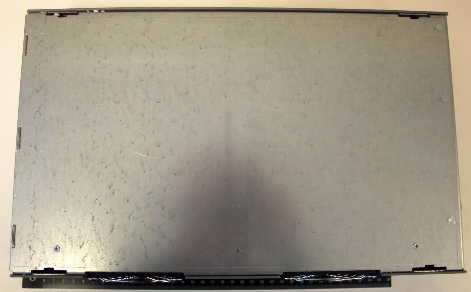
CGDLD4KW
Jul 15, 20204kW Electronic Lamp Driver
Equipment Class
DTS - Digital Transmission System