CGDSFSBData Transmission System applied with a Sensor Bridge for lamps
Nedap N. V.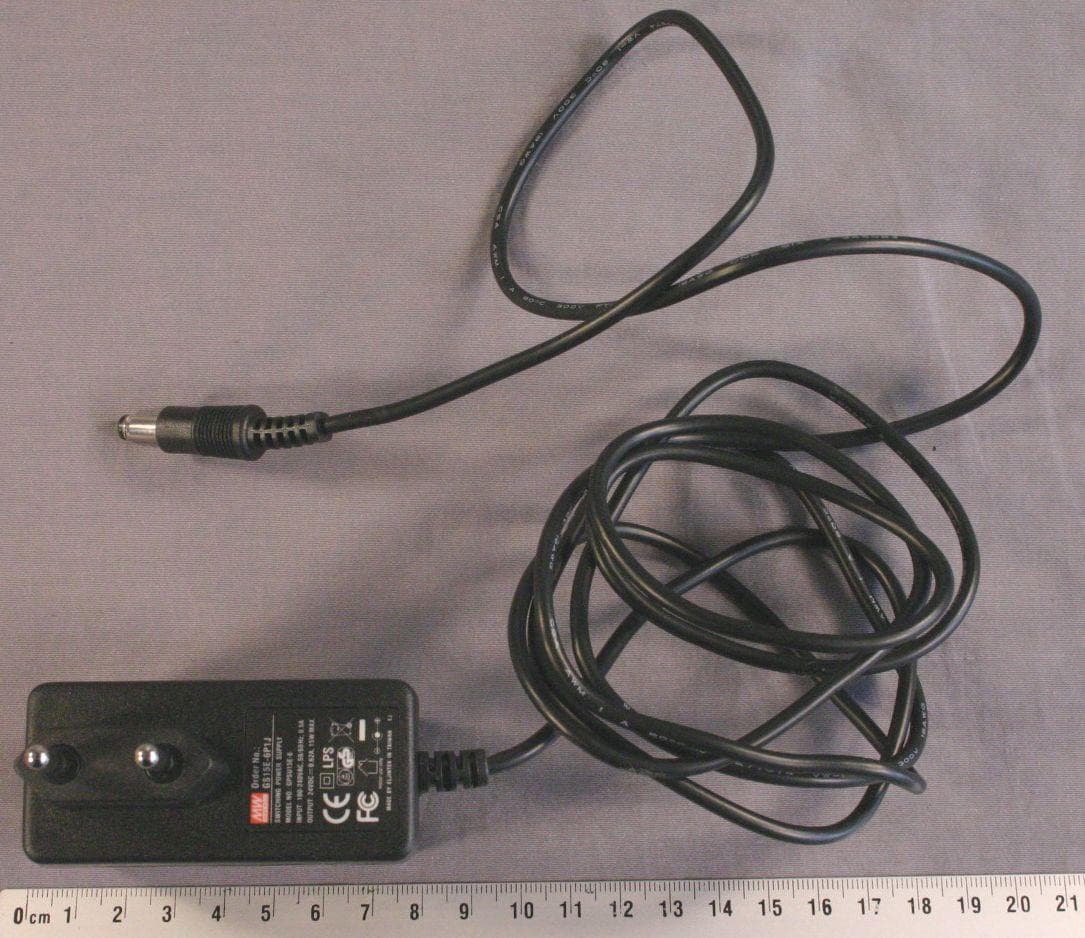
Click to zoom
Application Details
- Equipment Class
- DXX - Part 15 Low Power Communication Device Transmitter
- Date of Grant
- Mar 10, 2011
- Application Purpose
- Original Equipment
- Date of Application
- Mar 10, 2011
- Equipment Note
- Data Transmission System applied with a Sensor Bridge for lamps
- Frequency Range
- 2408.00000000 - 2475.00000000
- Company
- Nedap N. V.
- Country
- Netherlands
Documents & Files
Document Text
Text extracted from the exhibit documents filed with the FCC. Open a document above to read the original.
Users Manual
Page 1 of 7 Installation Manual PCB Sensor Bridge for the application example: Luxon Sensor Bridge February 2011 Page 2 of 7 1. Brief product description With the Luxon Sensor Bridge commercially available sensors can be added to the Nedap Luxon light control system. During the installation process the Sensor Bridge will become part of the wireless Senzafil Mesh Network, over which data is transferred. The light controller now can control light levels using data from remote sensors for light, motion and occupancy detection and from switches and 0-10V controls like electronic potentiometers. Figure 1. Installation example for the Luxon Sensor Bridge with HID lamps controlled via RF by a Mesh Network in a building with skylights Page 3 of 7 2. Assembly overview for the Luxon Sensor Bridge Figure 2. Overview Sensor Bridge assembly The Sensor Bridge is fitted in a rugged plastic housing with a sealing to obtain IP67 protection for dust and moist, see Figure 2. Cable glands shall be included, they must be mounted for IP67 protection. The PCB sensor bridge has a small cutout that should fit the notch in the cover to prevent mounting the PCB the wrong way. Page 4 of 7 3. Positioning The Sensor Bridge shall be placed at a maximum distance of 40 meters from the nearest node operating within the same group. Avoid using a long cable (>>20m) to the sensor. Note: The Sensor Bridge shall never be installed inside a metal power cabinet. This would impede wireless communication. Fig 3 No installation of the Luxon Sensor Bridge inside a metal enclosure 4. Mounting instructions for the Luxon Sensor Bridge Prior to fixation, assemble the two cable glands to the unit’s enclosure. If only one gland is to be used, close the other opening with an appropriate plug to maintain IP 67 enclosure protection level if necessary. The surface or wall mount Sensor Bridge shall be mounted using 2 ball or cylinder head screws with maximum head diameter of 9 mm, corresponding holes shall be (pre-)drilled 94 mm apart. See also figure 4. Figure 4. location and pinning of connectors in wall mount bottom part Page 5 of 7 Overview of inputs and outputs below, see also Fig.4 for locations. Supply (*) + +12 to +24Vdc +/- 5% Note that the voltage to be used depends on the used sensor Input current: 0.3A max. 0V 0V - Gnd Supply Alternative supply connection via DC-jack with 2mm centre pin, Centre pin is positive, shield is 0V - Gnd Sensor Supply Supply for sensor, same level as Supply + Current 200mA max. 0V 0V - Gnd Sensor Input Connect to sensor output. 5. Powering the Sensor Bridge system Fig 5 shows an installation example for the Luxon Sensor Bridge with sensor and mains adapter. Figure 5. Wiring overview for the Luxon Sensor Bridge system Powering: The Sensor Bridge is powered from a mains adapter or similar DC-source supplying 12 to 24V. This voltage is also available for the sensor, so you can choose the supply voltage depending on the voltage needed for the sensor to be used. Power connection via either a standard DC-plug or screw terminals. Many sensor types can be used: - Switches; - 1 to 10V dimmers (resistive and electronic potentiometers); - Light sensors; - Sensors for detection of movement and / or room occupancy. Safety notes: An isolated limited power supply shall be used. For USA/Canada use a UL-listed class 2 limited power supply (E.g. MEAN WELL type GS06U, GS12U) If a separate supply will be used for the sensor, this supply shall also meet the requirements for a class 2 limited power supply. Page 6 of 7 6. Specifications for application Luxon Sensor Bridge 7. FCC and IC Declarations for Luxon Sensor Bridge English: This device contains PCB Sensor Bridge p/n 7834802 with FCC ID: CGDSFSB and IC: 1444A-SFSB Compliance statement This device complies with part 15 of the FCC Rules and to RSS210 of Industry Canada. Operation is subject to the following two conditions: (1) this device may not cause harmful interference, and (2) this device must accept any interference received, including interference that may cause undesired operation. Déclaration Conformité Cet appareil se conforme aux normes RSS exemptés de license du Industry Canada. L'opération est soumis aux deux conditions suivantes (1) cet appareil ne doit causer aucune interférence, et (2) cet appareil doit accepter n'importe quelle interférence, y inclus interférence qui peut causer une opération non pas voulu de cet appareil. Warning Changes or modifications not expressly approved by the party responsible for compliance could void the user’s authority to operate the equipment. RF Exposure To comply with FCC RF exposure requirements for mobile transmitting devices, this transmitter should only be used or installed at locations where there is at least 20cm separation distance between the antenna and all persons. Operating temperature Safety EMC/Telecom -40 to +70°C EN60950 , UL916 EN301489-1, EN300328 V1.7.1 FCC47 part 15 and IC RSS210 Wire section range for the screw connector Enclosure protection degree IP67 (with both cable glands assembled correctly) Dimensions Diameter 130mm, height 70mm Max 1.5sqmm or AWG15 ESKV 16mm gland: 4.5 to 10mm ESKV 20mm gland: 6 to 13mm Cable clamp range Input Supply 10.5 to 28 Vdc, max 300mA 10.5 to 28 Vdc , max 200mA Sensor Operating Voltage Sensor Input Voltage 0 to 28 Vdc Page 7 of 7 8. Label artwork for application Luxon Sensor Bridge Label artwork for Sensor Bridge Wall Mount To scale: This device complies with part 15 of the FCC Rules and to RSS210 of Industry Canada. Operation is subject to the following two conditions: (1) this device may not cause harmful interference, and (2) this device must accept any interference received, including interference that may cause undesired operation. Luxon P/N: 8018669 Input: 12 to 24Vdc max 0.3A Enclosure IP67 rated – Suitable for wet locations Model: Sensor Bridge Wall Mount This device contains PCB Sensor Bridge p/n 7834802 with FCC ID: CGDSFSB IC: 1444A-SFSB S/N: xxxx xxxx Output: 1…
Text truncated - open the document above for the full version.
Users Manual
Option for Nedap Luxon wireless light control system The Sensor Bridge is introduced to add commercially available sensors to the Nedap Luxon light control system. Once installed the Sensor Bridge is part of the Senzafil Mesh Network. Sensor data is transferred by this RF network to minimize wiring efforts. Amongst the validated sensors you will find sensors to detect light level, movement or room occupancy. Now it is easy to add sensing capabilities to your Luxon E-series light control system to save more energy. The Luxon Sensor Bridge consists two main parts: The dome with the RF electronics and microcontroller The base is used for cable connections for power and sensor. Figure 1: Luxon Sensor Bridge, version for surface mounting Powering: The Sensor Bridge is powered from a mains adapter or similar DC-source supplying 12 to 24V. This voltage is also available for the sensor, so you can choose the supply voltage depending on the voltage needed for the sensor to be used. Power connection via either a standard DC-plug or screw terminals. Option for Nedap Luxon wireless light control system LIGHT SENSOR MOVEMENT SENSOR MAINS ADAPTER NEDAP RF SENSOR BRIDGE Figure 2: Wiring overview for the Luxon Sensor Bridge Compatible sensors: Many sensor types can be used: - Switches; - 1 to 10V dimmers (resistive and electronic potentiometers); - Light sensors; - Sensors for detection of movement and / or room occupancy. To select an appropriate sensor that fits your application and your preferences, please use the listing available on our web site www.nedaplightcontrols.com. The Sensor Bridge may only be installed and configured by qualified and trained personnel. For an installation example please see figure 3 below. The Sensor Bridge can be ordered for surface mounting or for recessed mounting; the dome should always point downwards if mounted at approximately the same height as the Senzafil lamp drivers. For recessed mounting, both clamps can be used to secure the unit to a ceiling element. After finishing the connections, the dome shall be secured to the base using four torx screws. After powering the Sensor Bridge it shall be configured using the Senzafil Configuration Tool. From the pick list you can easily select the used sensor with its characteristics. Option for Nedap Luxon wireless light control system SKYLIGHT SKYLIGHT NEDAP LUXON LIGHT CONTROLLER SENSOR DATA FLOW IN SENZAFIL RF MESH NETWORK NEDAP LUXON SENSOR BRIDGE WITH LIGHT SENSOR HID LAMPS WITH NEDAP LAMP BALLAST Figure 3: Installation example for the Sensor Bridge with HID lamps controlled via the Wireless Senzafil Mesh Network in a building with skylights. Option for Nedap Luxon wireless light control system Luxon Sensor Bridge for surface mounting: 8018669, ordering nr. 9949348 Luxon Sensor Bridge for recessed mounting: 8019037, ordering nr. 9949356 Description DescriptionDescription Description Details DetailsDetails Details Supply Voltage 10 to 28VDC Supply current Sensor Bridge: max 100mA, standby < 20mA External sensor: max 200mA Mains adapter specification 12V / 4W or 24V / 6W Dimensions Diameter: 130 mm, Height 70 mm Weight 0.23kg including cable glands Enclosure protection IP67 (the en IP67 (the enIP67 (the en IP67 (the enclosed cable glands must be used properly) closed cable glands must be used properly)closed cable glands must be used properly) closed cable glands must be used properly) Housing colors Base: light gray, top: milky grey-white Connector power: standard DC jack with 2.0 mm centre pin or 2 screw terminals 30-18 AWG, or 0.25 to 1.5 sq.mm. sensor: 3 screw terminals 30-18 AWG, or 0.25 to 1.5 sq.mm. Safety United States and Canada United States and Canada United States and Canada United States and Canada An UL listed An UL listed An UL listed An UL listed mains adapter mains adapter mains adapter mains adapter shall shallshall shall be used be usedbe used be used that meets the NEC Class 2 requirements that meets the NEC Class 2 requirementsthat meets the NEC Class 2 requirements that meets the NEC Class 2 requirements The Sensor bridge is designed to meet UL6 The Sensor bridge is designed to meet UL6The Sensor bridge is designed to meet UL6 The Sensor bridge is designed to meet UL619 1919 19 Europe EuropeEurope Europe An AnAn An EN60950 compliant mains adapter must be used EN60950 compliant mains adapter must be usedEN60950 compliant mains adapter must be used EN60950 compliant mains adapter must be used EMC United States a United States aUnited States a United States and Canada nd Canada nd Canada nd Canada FCC47 part FCC47 part FCC47 part FCC47 part 15 15 15 15 Europe EuropeEurope Europe EN ENEN EN301 301301 301 489 489489 489- -- -1 and 489 1 and 4891 and 489 1 and 489- -- -3 33 3 EN300 328 EN300 328EN300 328 EN300 328 Temperature Operating 0 Operating 0 Operating 0 Operating 0 – –– – 60°C, Storage 60°C, Storage 60°C, Storage 60°C, Storage - -- -20 to 80°C 20 to 80°C20 to 80°C 20 to 80°C Humidity 25 to 95 % RH. Condensing and icing max 5% of time 25 to 95 % RH. Condensing and icing max 5% of time25 to 95 % RH. Condensing and icing max 5% of time 25 to 95 % RH. Condensing and icing max 5% of time Option for Nedap Luxon wireless light control system F FF FCC Declarations CC DeclarationsCC Declarations CC Declarations Compliance statement (part 15.19) Compliance statement (part 15.19) Compliance statement (part 15.19) Compliance statement (part 15.19) This device complies with part 15 of the FCC Rules and to RSS210 of Industry Canada. Operation is subject to the following two conditions: (1) this device may not cause harmful interference, and (2) this device must accept any interference received, including interference that may cause undesired operation. Déclaration Conformit Déclaration ConformitDéclaration Conformit Déclaration Conformité éé é Cet appareil se conforme aux normes RSS exemptés de license du Industry Canada. L'opération est soumis aux deux conditions suivantes (1) cet appareil ne doit causer aucu…
Text truncated - open the document above for the full version.
Cover Letter(s)
Groenlo, 20 January 2011 Return address: PO Box 6, 7140 AA Groenlo, The Netherlands ATCB Attn.: Mrs. M. Bosley Certification Department 6731 Whittier Avenue, Suite C110 McLean, Virginia 22101 USA Dear Mrs. Bosley, We, N.V. Nederlandsche Apparatenfabriek "Nedap", we hereby would like to apply for Limited Modular Approval certification of the following device: FCC ID : CGDSFSB FRN : 0007696149 Brand : Nedap Model : PCB Sensor Bridge Description : A Digital Transmission System in the band 2400 – 2483.5 MHz for a mesh network for lamp drivers The following PDF files (exhibits) are electronically submitted: 1. Cover letter (this document) 2. Request of confidentiality 3. Form 731 4. Antenna information 5. Bills of material (BOM) 6. Circuit diagrams 7. Block diagram 8. Photographs of the PCB Sensor Bridge 9. Photographs of Sensor Bridge Wall Mount, an example application 10. FCC ID Label artwork 11. Label location 12. Technical description and block diagram 13. Test report in conformity with 47 CFR Part 15 14. Test setup photographs 15. Installation manual 16. RF Exposure 17. Brochure 18. Request putting statement 15.19 (a)(3) in the manual NOTE: We would like to request for the 15.19 (a) (3) statement to go in the manual due to size. Best regards, N.V. Nederlandsche Apparatenfabriek “Nedap“ Jacques Hulshof Approbation Management
Cover Letter(s)
Return address: PO Box 6, 7140 AA Groenlo, The Netherlands ATCB Attn.: Mrs. M. Bosley Certification Department 6731 Whittier Avenue, Suite C110 McLean, Virginia 22101 USA Groenlo, 13 January 2011 Subject: Request of Confidentiality FCC ID: CGDSFSB Dear Mrs. Bosley, Pursuant to section 0.457(d)(2)(i) and Section 0.459 of the FCC rules we herewith request the following exhibits, related to this application for FCC ID : CGDSFSB Applicant : N.V. Nederlandsche Apparatenfabriek “Nedap” Brand : Nedap Sanzafil Model : PCB Sensor Bridge to be withheld from public inspection and to be kept confidential. The contents of these exhibits may not be disclosed to other parties than N.V. Nederlandsche Apparatenfabriek "NEDAP" and TÜV Rheinland Electronic Products & Services (EPS) B.V.: 1. Bill of materials 2. Circuit diagram 3. Block diagram 4. Theory of operation (technical description) The reason for this request for confidentiality is that the information contained in the exhibits as listed above has been classified as company confidential. Disclosure of any portion of this information to other parties would cause substantial competitive harm. Best regards, N.V. Nederlandsche Apparatenfebriek “Nedap” Jacques Hulshof Approbation Management
Cover Letter(s)
Return address: PO Box 6, 7140 AA Groenlo, The Netherlands ATCB Attn.: Mrs. M. Bosley Certification Department 6731 Whittier Avenue, Suite C110 McLean, Virginia 22101 USA Subject: Statement requirements modular approval FCC Part 15.212 Groenlo, 04 March 2011 Dear Mrs. Bosley, Pursuant to section 0.457(d)(2)(i) and Section 0.459 of the FCC rules we herewith request the following exhibits, related to this application for FCC ID : CGDSFSB Applicant : N.V. Nederlandsche Apparatenfabriek “Nedap” Brand : Nedap Sanzafil Model : PCB Sensor Bridge We would like above product have approved as a modular approval specific to FCC Part 15.212 Limited Modular Transmitter Unlicensed Approval for low power transmitter modules for use in Nedap’s host devices: The requirements of the FCC Part 15.212 are met as follows: 1. The modular transmitter nRF2401A on the PCB Sensor Bridge has an own RF shielding in order to be compliant to the FCC rules. See Exhibit “08r1_Photoreport CGDSFSB.pdf”. 2. The modular transmitter nRF2401A has buffered data inputs with a buffer of maximum 256 bits and a maximum data rate of 1000 kbps see page 10 and 1 of exhibit “21_Blockdiagram_operational description nRF2401A CGDSFSB.pdf”. 3. The modular transmitter nR2401A has no own power supply regulation and requires an input voltage of 3.3 Vdc. The voltage is delivered by the PCB Acsens Sensor. See Figure 4 page 4 of exhibit “09r1_Photo report Wall Mount with CGDSFSB.pdf”. This PCB Acsens Sensor again is powered by a mains adapter with an output power of +12 to 24 VDC ± 5%, see page 5 of “15r1_Installation Manual PCB SensorBridge CGDSFSB.pdf” 4. An integrated antenna is applied see exhibit “04_Antenna information CGDSFSB.pdf”. 5. The EUT was tested with the PCB Acsens Sensor mentioned under requirement 3. This PCB has a connector for a mains plug adaptor for having supply. To prevent the PCBs from damaging the devices are placed in a plastic enclosure see “15r1_Installation Manual PCB SensorBridge CGDSFSB.pdf”. 6. An exhibit label (including FCC ID) has been included in the exhibits “10r1_Label artwork CGDSFSB.pdf” and “11r1_Label location CGDSFSB.pdf”. This device is only installed in Nedap’s end products and “15r1_Installation Manual PCB SensorBridge CGDSFSB.pdf” shows and instructs in what manner the end product needs labeling. 7. The PCB Sensor Bridge is compliant with all applicable FCC rules. Instructions for maintaining compliance are given in the “15r1_Installation Manual PCB SensorBridge CGDSFSB.pdf. 8. The PCB Sensor bridge is compliant with all applicable RF exposure requirements for transmitter devices. Best regards, N.V. Nederlandsche Apparatenfabriek “Nedap” Jacques Hulshof Approbation Management
External Photos
Page 1 of 10 Digital Transmission System Wall Mount Brand Nedap Luxon with Model PCB Sensor Bridge Photographs Description of EUT: Manufacturer: Brand mark: Model: Digital Transmission System N.V. Nederlandse Apparatenfabriek “Nedap” Nedap Luxon Sensor Bridge Wall Mount Page 2 of 10 Description of item Description of EUT : Digital Transmission System Manufacturer : N.V. Nederlandsche Apparatenfabriek “Nedap” Brand : Nedap Luxon Model : Sensor Bridge Wall Mount Applicant information Applicant's representative : Mr. Jacques Hulshof Company : N.V. Nederlandsche Apparatenfabriek “Nedap” Address : Parallelweg 2 Postal code : 7141 DC City : Groenlo PO-box : 6 Postal code : 7140 AA City : Groenlo Country : The Netherlands Telephone number : +31 (0) 544 471111 Telefax number : +31 (0) 544 463475 FCC ID inside CGDSFSB IC inside 1444A-SFSB January 19, 2011 Description of EUT: Manufacturer: Brand mark: Model: Digital Transmission System N.V. Nederlandse Apparatenfabriek “Nedap” Nedap Luxon Sensor Bridge Wall Mount Page 3 of 10 Table of contents 1 SENSOR BRIDGE WALL MOUNT .................................................................................................................................. 4 1.1 TOTAL OVERVIEW OF THE PRODUCT ................................................................................................................................ 4 1.2 TOP VIEW ........................................................................................................................................................................ 5 1.3 BOTTOM VIEW ................................................................................................................................................................. 5 1.4 VIEW, COVER REMOVED .................................................................................................................................................. 6 1.5 INSIDE VIEW .................................................................................................................................................................... 6 1.6 INSIDE VIEW, PCB SENSOR BRIGDE REMOVED ................................................................................................................ 7 1.7 LOCATION OF LABEL ON SENSOR BRIDGE WALL MOUNT ............................................................................................... 8 1.8 SENSOR BRIDGE WALL MOUNT LABELED READABLE ..................................................................................................... 8 1.9 WARNING TEXT READABLE ............................................................................................................................................. 9 1.10 POWER SUPPLY ............................................................................................................................................................... 9 1.11 LABEL ARTWORK OF THE WALL MOUNT SENSOR BRIDGE ............................................................................................ 10 Description of EUT: Manufacturer: Brand mark: Model: Digital Transmission System N.V. Nederlandse Apparatenfabriek “Nedap” Nedap Luxon Sensor Bridge Wall Mount Page 4 of 10 1 Sensor Bridge Wall Mount Sensor Bridge Wall Mount is an example application. In the following pictures are shown in which the PCB Sensor Bridge can be installed. All the measurements have been performed with this plastic enclosure. 1.1 Total overview of the product Description of EUT: Manufacturer: Brand mark: Model: Digital Transmission System N.V. Nederlandse Apparatenfabriek “Nedap” Nedap Luxon Sensor Bridge Wall Mount Page 5 of 10 1.2 Top view 1.3 Bottom view Description of EUT: Manufacturer: Brand mark: Model: Digital Transmission System N.V. Nederlandse Apparatenfabriek “Nedap” Nedap Luxon Sensor Bridge Wall Mount Page 6 of 10 1.4 View, cover removed 1.5 Inside view Description of EUT: Manufacturer: Brand mark: Model: Digital Transmission System N.V. Nederlandse Apparatenfabriek “Nedap” Nedap Luxon Sensor Bridge Wall Mount Page 7 of 10 1.6 Inside view, PCB Sensor Brigde removed Description of EUT: Manufacturer: Brand mark: Model: Digital Transmission System N.V. Nederlandse Apparatenfabriek “Nedap” Nedap Luxon Sensor Bridge Wall Mount Page 8 of 10 1.7 Location of label on Sensor Bridge Wall Mount 1.8 Sensor Bridge Wall Mount labeled readable Description of EUT: Manufacturer: Brand mark: Model: Digital Transmission System N.V. Nederlandse Apparatenfabriek “Nedap” Nedap Luxon Sensor Bridge Wall Mount Page 9 of 10 1.9 Warning text readable 1.10 Power Supply Description of EUT: Manufacturer: Brand mark: Model: Digital Transmission System N.V. Nederlandse Apparatenfabriek “Nedap” Nedap Luxon Sensor Bridge Wall Mount Page 10 of 10 1.11 Label artwork of the Wall Mount Sensor Bridge
ID Label/Location Info
Label artwork for PCB Sensor Bridge 7834802 To scale: Luxon P/N: 7834802 Input: 12 to 24Vdc max 0.05A TYPE: PCB Sensor Bridge FCC-ID: CGDSFSB IC: 1444A-SFSB S/N: B1070001 Input: 3.3Vdc max 0.05A Scale 200%
ID Label/Location Info
Page 1 of 4 Limited Modular Approval Digital Transmission System Brand Nedap Luxon Model PCB Sensor Bridge Label Location Description of EUT: Manufacturer: Brand mark: Model: Digital Transmission System N.V. Nederlandse Apparatenfabriek “Nedap” Nedap Luxon PCB Sensor Bridge Page 2 of 4 Description of item Description of EUT : Digital Transmission System Manufacturer : N.V. Nederlandsche Apparatenfabriek “Nedap” Brand : Nedap Luxon Model : PCB Sensor Bridge Applicant information Applicant's representative : Mr. Jacques Hulshof Company : N.V. Nederlandsche Apparatenfabriek “Nedap” Address : Parallelweg 2 Postal code : 7141 DC City : Groenlo PO-box : 6 Postal code : 7140 AA City : Groenlo Country : The Netherlands Telephone number : +31 (0) 544 471111 Telefax number : +31 (0) 544 463475 FCC ID CGDSFSB IC 1444A-SFSB January 11, 2011 Description of EUT: Manufacturer: Brand mark: Model: Digital Transmission System N.V. Nederlandse Apparatenfabriek “Nedap” Nedap Luxon PCB Sensor Bridge Page 3 of 4 Table of contents 1 LABEL LOCATION OF THE PCB SENSOR BRIDGE ................................................................................................. 4 1.1 LABEL OF THE PCB SENSOR BRIDGE .............................................................................................................................. 4 1.2 LABEL INFORMATION ...................................................................................................................................................... 4 Description of EUT: Manufacturer: Brand mark: Model: Digital Transmission System N.V. Nederlandse Apparatenfabriek “Nedap” Nedap Luxon PCB Sensor Bridge Page 4 of 4 1 Label location of the PCB Sensor Bridge 1.1 Label of the PCB Sensor Bridge 1.2 Label information
Internal Photos
Page 1 of 7 Limited Modular Approval Digital Transmission System Brand Nedap Luxon Model PCB Sensor Bridge Interior Photographs Description of EUT: Manufacturer: Brand mark: Model: Digital Transmission System N.V. Nederlandse Apparatenfabriek “Nedap” Nedap Luxon PCB Sensor Bridge Page 2 of 7 Description of item Description of EUT : Digital Transmission System Manufacturer : N.V. Nederlandsche Apparatenfabriek “Nedap” Brand : Nedap Luxon Model : PCB Sensor Bridge Applicant information Applicant's representative : Mr. Jacques Hulshof Company : N.V. Nederlandsche Apparatenfabriek “Nedap” Address : Parallelweg 2 Postal code : 7141 DC City : Groenlo PO-box : 6 Postal code : 7140 AA City : Groenlo Country : The Netherlands Telephone number : +31 (0) 544 471111 Telefax number : +31 (0) 544 463475 FCC ID CGDSFSB IC 1444A-SFSB January 13, 2011 Revised March 2, 2011 Added photograph with the metal shield removed and added photo of revised label Description of EUT: Manufacturer: Brand mark: Model: Digital Transmission System N.V. Nederlandse Apparatenfabriek “Nedap” Nedap Luxon PCB Sensor Bridge Page 3 of 7 Table of contents 1 OVERVIEW OF THE PCB SENSOR BRIDGE ............................................................................................................... 4 1.1 PCB FRONT VIEW, COMPONENT SIDE ........................................................................................................................... 4 1.2 PCB FRONT VIEW, COMPONENT SIDE, METAL SHIELD REMOVED.................................................................................. 4 1.3 PCB BACK SIDE .............................................................................................................................................................. 5 1.4 LABEL OF THE PCB SENSOR BRIDGE .............................................................................................................................. 6 1.5 PCB SENSOR BRIDGE MOUNTED IN AN ENCLOSURE ........................................................................................................ 7 Description of EUT: Manufacturer: Brand mark: Model: Digital Transmission System N.V. Nederlandse Apparatenfabriek “Nedap” Nedap Luxon PCB Sensor Bridge Page 4 of 7 1 Overview of the PCB Sensor Bridge 1.1 PCB Front view, component side 1.2 PCB Front view, component side, metal shield removed Description of EUT: Manufacturer: Brand mark: Model: Digital Transmission System N.V. Nederlandse Apparatenfabriek “Nedap” Nedap Luxon PCB Sensor Bridge Page 5 of 7 1.3 PCB back side Description of EUT: Manufacturer: Brand mark: Model: Digital Transmission System N.V. Nederlandse Apparatenfabriek “Nedap” Nedap Luxon PCB Sensor Bridge Page 6 of 7 1.4 Label of the PCB Sensor Bridge Description of EUT: Manufacturer: Brand mark: Model: Digital Transmission System N.V. Nederlandse Apparatenfabriek “Nedap” Nedap Luxon PCB Sensor Bridge Page 7 of 7 1.5 PCB Sensor Bridge mounted in an enclosure
RF Exposure Info
Groenlo, 20 January 2011 Declaration on radiation safety standard conformance To whom it may concern: N.V. Nederllandsche Apparatenfabriek “Nedap” Parallelweg 2 7141 DC Groenlo The Netherlands declares that the following product Description : 2.45 GHz Data Transmission System FCC ID : CGDSFSB Manufacturer : N.V. Nederlandsche Apparatenfabriek “Nedap” Brand : Nedap Luxon Type/model number : PCB Sensor Bridge has a rated RF power of 2.63 mW, which means that the worst case prediction of power density (100% reflection) at 20 cm distance (worst case) can be calculated as follows: 2 **4R EIRP S π = (power density without reflection) 2 2 **4 *2 R EIRP S π = (power density with 100% reflection) 2 2 **4 *2 R EIRP S π = = 2 )20(* 63.2 cm mW π = 0.002 mW/cm² (Limit = 0.2 mW/cm²) Best regards, N.V. Nederlandsche Apparatenfabriek “Nedap” Jacques Hulshof Approbation Management
Test Report
Testing and certification of electronic and electric appliances, systems, installations and telecommunication systems TÜV Rheinland EPS B.V. P.O. Box 15 9822 ZG Niekerk (NL) Smidshornerweg 18 9822 TL Niekerk (NL) Telephone: +31 594 505005 Telefax: +31 594 504804 E-mail: [email protected] Web: www.tuv-eps.com Project number: 10052701.fcc01 Page 1 of 24 TEST REPORT CONCERNING THE COMPLIANCE OF A DIGITAL TRANSMISSION SYSTEM OPERATING IN THE FREQUENCY RANGE 2408 – 2475 MHz, BRAND NEDAP SENZAFIL, MODEL PCB SENSOR BRIDGE WITH 47 CFR PART 15 (10-1-09 Edition). 10052701.fcc01 January 13, 2011 FCC listed Industry Canada VCCI Registered R&TTE, LVD, EMC Notified Body : : : : 90828 2932G-1 R-1518, C-1598 1856 Test specification(s): Description of EUT: Manufacturer: Brand mark: Model: FCC ID: FCC Part 15 Digital Transmission System N.V. Nederlandsche Apparatenfabriek “Nedap” Nedap Luxon PCB Sensor Bridge CGDSFSB Project number : 10052701.fcc01 Page 2 of 24 MEASUREMENT/TECHNICAL REPORT N.V. Nederlandsche Apparatenfabriek “Nedap” Model : PCB Sensor Bridge FCC ID: CGDSFSB January 13, 2011 This report concerns: Limited Modular Approval Class 2 change Verification Equipment type: Digital Transmission System Report prepared by: Name : Richard van der Meer Company name : TÜV Rheinland EPS B.V. Address : Smidshornerweg 18 Postal code/city : 9822 TL Niekerk Mailing address : P.O. Box 15 Postal code/city : 9822 ZG Niekerk Country : The Netherlands Telephone number : + 31 594 505 005 Telefax number : + 31 594 504 804 E-mail : [email protected] The data taken for this test and report herein was done in accordance with 47 CFR Part 15 (10-1-09 Edition) and the measurement procedures of ANSI C63.4-2009. TÜV Rheinland EPS B.V. at Niekerk, The Netherlands, certifies that the data is accurate and contains a true representation of the emission profile of the Equipment Under Test (EUT) on the date of the test as noted in the test report. I have reviewed the test report and find it to be an accurate description of the test(s) performed and the EUT so te…
Text truncated - open the document above for the full version.
Contact Information
Applicant
Reinold Hubers(Approbation Officer)
Test Firm
TUV Rheinland Nederland B.V.Wiebe Boekema
Technical Specifications
| # | Rule Parts | Frequency Range | Power Output |
|---|---|---|---|
| 1 | 15C | 2.41 GHz - 2.48 GHz | - |
Other Applications from Nedap N. V.
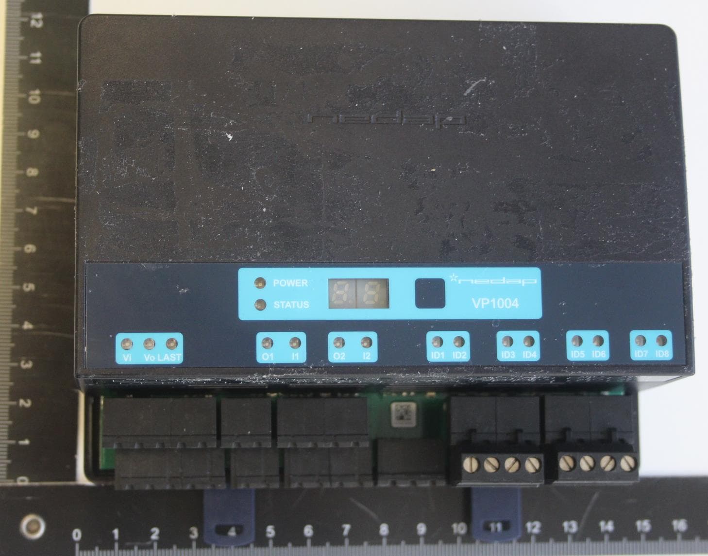
CGDVP1004B
Jan 25, 2021VP1004-B System
Equipment Class
DCD - Part 15 Low Power Transmitter Below 1705 kHz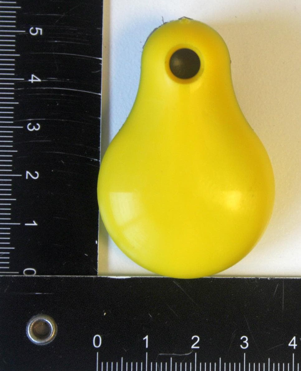
CGDFERPH
Dec 15, 2020SMARTTAG EAR
Equipment Class
DXX - Part 15 Low Power Communication Device Transmitter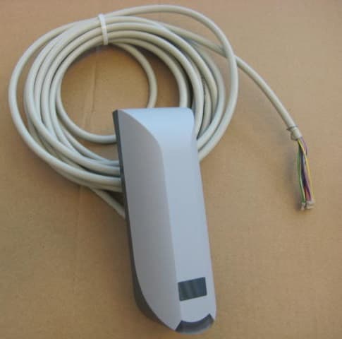
CGDNVR2001
Dec 01, 2020Reader for 120 kHz and 13.56 MHz cards and also NFC, QR and BT
Equipment Class
DCD - Part 15 Low Power Transmitter Below 1705 kHz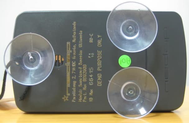
CGDBOOSTER11
Nov 30, 2020Long-range vehicle and driver identification tag
Equipment Class
DSR - Part 15 Remote Control/Security Device Transceiver
CGDLD4KW
Jul 15, 20204kW Electronic Lamp Driver
Equipment Class
DTS - Digital Transmission System