CGDUPASSREACHUHF RFID Reader for EPC Gen2 Class 1 tags
Nedap N. V.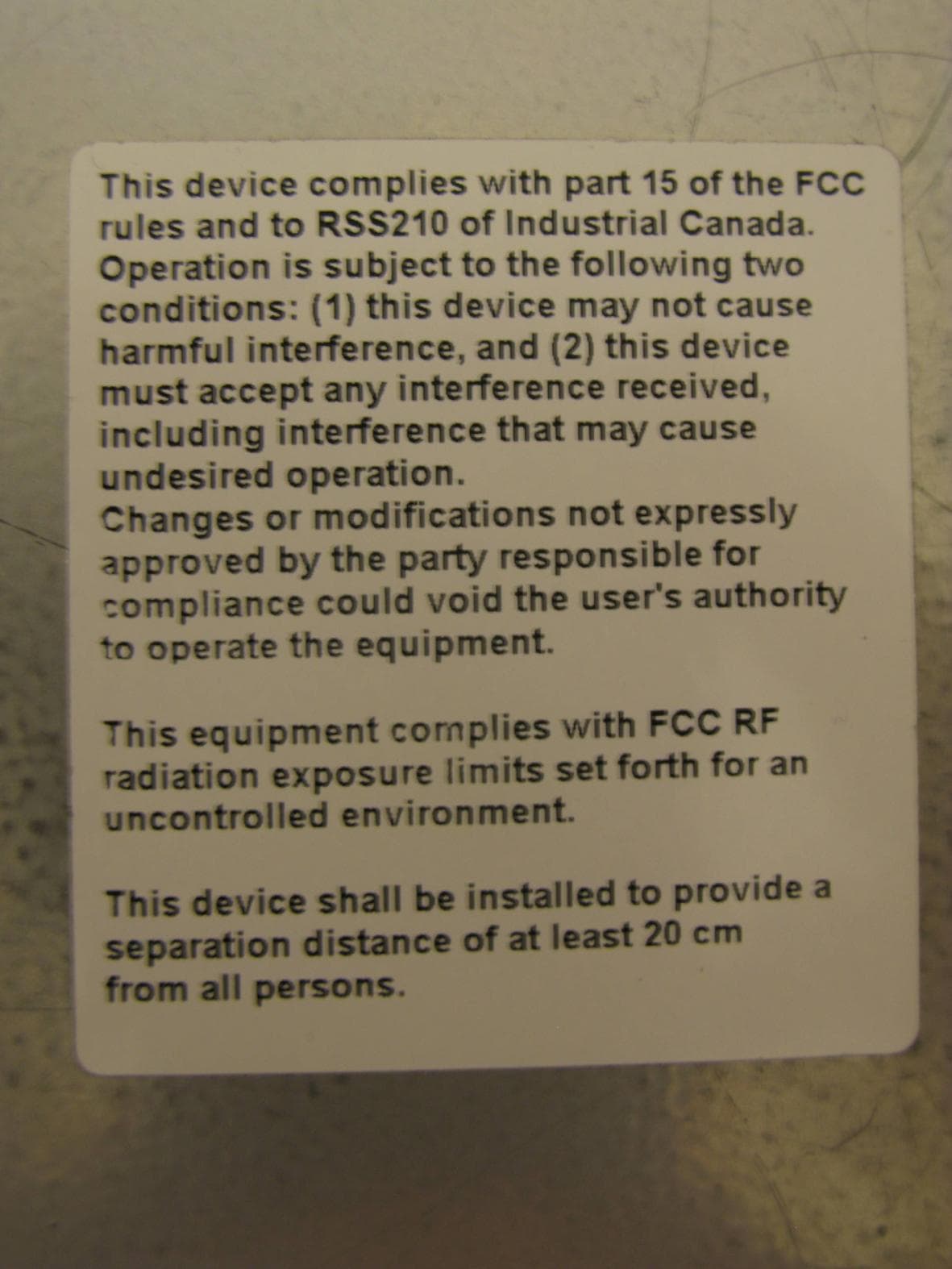
Click to zoom
Application Details
- Equipment Class
- DTS - Digital Transmission System
- Date of Grant
- May 20, 2010
- Application Purpose
- Original Equipment
- Date of Application
- May 19, 2010
- Equipment Note
- UHF RFID Reader for EPC Gen2 Class 1 tags
- Frequency Range
- 902.70000000 - 927.20000000
- Company
- Nedap N. V.
- Country
- Netherlands
Documents & Files
Document Text
Text extracted from the exhibit documents filed with the FCC. Open a document above to read the original.
Users Manual
Long range is now within reach! UHF based long range ID at up to 4 meters [12ft]. Product overview Nedap, expertise in Vehicle Identification Nedap- founded in 1929 and based in the Netherlands – employs about 600 employees worldwide. Nedap AVI has an outstanding ex- pertise in RFID technology and vehicle access applications. Our RFID solutions are tailored for vehicle applications, ensuring reliable op- eration for any vehicle gate environment. As one of the pioneers in RFID technology during decades, Nedap has established an impressive track record of vehicle identification installa- tions worldwide in many different industries. Nedap’s AVI system is considered the best in the market. Features as simultaneous driver and vehicle identification make the Nedap offering unique. Therefore Nedap is the perfect fit to any long range vehicle access application, offering a full product line for vehicle access. The latest addition to the product line, the uPASS Reach, is based on years of experience and expertise in this market. Headquarters Nedap AVI PO Box 103 7140 AC Groenlo The Netherlands T: +31 544 471 666 F: +31 544 464 255 Americas Nedap US Office 500 W. Main, Suite 301 Branson, MO 65616 USA Asia Nedap Asia Office 391 Orchard Road #23-01 Ngee Ann City Tower B Singapore 238874 Middle East FZE West Wing 6, Block A, Office 227 Dubai Aiport Free Zone (DAFZA) Parallelweg 2e 7141 DC Groenlo The Netherlands E: [email protected] www.nedapavi.com T: 417 339 7368 F: 417 337 8889 E: [email protected] T: +65 683 280 51 F: +65 683 280 52 E: [email protected] T: +971 (0)4 214 6260 F: +971 (0)4 214 6262 E: [email protected] Big range. Little price. For years, others have claimed to offer long range UHF performance at a competitive price, but none have really been able to deliver. Until now! Introducing the uPASS Reach reader from Nedap AVI. Developed from decades of experience with RFID technology and timed to take advantage of new, superior Gen 2 tag read characteristics, the uPASS Reach reader is a culmination of both experience and innovation. Featuring a 4 meter [12ft] read range, superior to all conventional Prox systems, the uPASS Reach offers a true long range solution for car parks, gated communities, and employee parking lots. Now there’s a uPASS Reach reader that offers maximum distance at an affordable price. uPASS Reach reader For full product information visit www.nedapavi.com uPASS Reach reader uPASS READER uPASS Reach reader Long range UHF parking access reader Operating frequency: 865 -955 MHz Dimensions: 7.9 x 8.7 x 1.8 in [200 x 220 x 45 mm] Detection range: up to 12 ft [4m] Interfaces: RS232, RS422 and USB Outputs: Wiegand and Magstripe ISO 7811/2 Part nr: 9942319 uPASS Reach Reg I 9945466 uPASS Reach Reg II + III 9945474 uPASS Reach Reg Japan TAGS UHF windshield sticker Single ID vehicle tag Identification: Vehicle ID Part nr: 9942327 UHF Windshield Tag 9942335 UHF Windshield Tag Tamperproof UHF ISO tag Single ID vehicle tag Identification: Vehicle ID Part nr: 9942344 ACCESSORIES UHF Weather hood Part nr: 7591152 Pole mounting kit Part nr: 9943803 Adjustable wall mounting kit Part nr: 9875840 UHF ISO tag UHF windshield sticker Adjustable wall mounting kit UHF Weather hood Pole mounting kit A very limited read range, increased risk of congestion and, most of all, inconvenience for the user to come to a full stop and open the window to present a badge. All major disadvantages of a proximity installation. The uPASS Reach is the perfect cure to the problems characteristic of prox and it’s ideally suited for upgrading those installations as the reader can easily be installed on a gooseneck with no need for additional mounting accessories or rewiring. uPASS Reach is a 865-955 MHz reader and EPC Gen 2 passive tag based system. With readers installed at a height between 1.2 and 2 meters [4-6.6 ft]. A long range UHF tag visible in direct line of sight will be identified from up to 4 meters [12 ft]. The reader output allows the access control or parking system to open the gate when authorized without the need for card readers or PIN pads. A built- in, high intensity LED provides visual feedback to the user that the tag has been read. Passive, maintenance free and customized tags The system is based on passive Gen 2 UHF tags that provide superior read quality to previous tag standards. Plus, they are both battery and maintenance free. Tags are mounted inside the vehicle behind the windshield. The thin, flexible, UHF sticker format is easy to install and has a windshield compatible adhesive to ensure proper mounting. For added security, tamperproof - break upon removal- tags are also available. Nedap customized UHF tags have a customer specific number sequence compatible to your application. The number is also printed on the tag allowing easy and fast enrolment of tags into a management system. An additional printed barcode makes it even easier. Security authentication features are included to provide data integrity and to prevent cloning of tags. In addition, Hybrid UHF-HF cards are available that support UHF and all smartcard technologies used worldwide for access control and time & attendance solutions. Plug &Play operation As with all of Nedap’s AVI systems, the uPASS Reach reader features open industry communication. This allows seamless integration into any existing or new access control or parking management system and makes the uPASS Reach reader ideal for upgrading any existing Wiegand reader installation. The uPASS Reach reader has an integrated fine-tuned antenna in an elegant and compact enclosure ideal for outdoor (IP65) as well as indoor applications. The reader is compliant with ISO 18000-6c and EPCglobal Gen2 standards. A specially designed mounting kit and protection hood are available to attach the reader to a gooseneck or pole. Reduced Install Costs = Increased Value Easy to mount and a cinch to integrate with existing wiring and even able to be mounted directly to metal, …
Text truncated - open the document above for the full version.
Users Manual
Install the windshield tag horizontal on the inside of the windshield. For more Read lobe characteristics Application note uPASS Reach This application note describes the installation of the uPASS Reach reader for parking entry control applications. The uPASS Reach can identify an AVI tag from distances up to max. 4 meters [12 ft]. Ensure the tag is positioned on the same side of the windshield as the reader • • Present the tag in line-of-sight to the reader. • This document is based on a windshield angle of 45°. Tilt the reader with a • Parking uPASS Reach installed on a pole at the barrier. Figure 2: uPASS Reach pole mounting, uPASS Reach installed at ° degrees anglea 45 4 5 ° a n g l e Example of a windshield tag is located. 45 ° facing the windshield to ensure optimal alignment between reader and tag. Onto a pole, located directly behind the barrier, using the pole mounting kit (7591152). Installation height between 1,20 and max. 2 meters from ground level. • • Use of windshield mounted tags • Position reader; 1 2 3 Item Parameters Description Between 1.20 and max 2 meters [6 ft] above driving lane ground level Mounting height Mounting position Frequency setting Onto a pole directly mounted behind the barrier Standard frequency, in case of multi-lane application, use frequency offset. Figure 1: detection angle 45 degrees information see the Windshield Tag Installsheet. • Tilt the reader with a 45facing the windshield to ensure optimal alignment ° between reader and tag. Multiple uPASS Reach readers Figure 4: Multi-lane application with the uPASS Reach The uPASS Reach can also be mounted onto an existing goose neck or uPASS Reach installed on goose neck or pedestral pedestal in front of the barrier, using the weather protection hood (9943803). When there is a gate column located in front off the barrier, the uPASS Reach can ItemDescription Parameters installed at a 45° degrees angle Figure 3: uPASS Reach is installed on a gooseneck Table : Application issues when uPASS Reach is mounted onto gooseneck Mounting onto an existing goose neck, pedestal Position uPASS Reach or gate column. For new installations position the goose neck or pedestal 2,5 to 3 meter [8 - 10 ft] before the barrier 2 3 Position the reader at about 1,3 meter [4 ft] from ground level (average car side window height). Width reading angle 45° 1 Mounting height Use of UHF Combi Card Present the tag in line of sight One reader required per driving direction Use frequency offset to avoid interference. See the application note UHF dense • • • • 2 , 5 - 3 m e t e rs 1,3 m e t e r s be mounted directly onto the gate column. reader mode.
Users Manual
2010-04-16 Part.no. 5276888 This information is furnished for guidance, and with no guarantee as to its accuracy or completeness; its publication conveys no license under any patent or other right, nor does the publisher assume liability for any consequence of its use; specifica- tions and availability of goods mentioned in it are subject to change without notice; it is not to be reproduced in any way, in whole or in part, without the written consent of the publisher. © Nedap AVI Page 1 of 27 uPASS Reach Installation Guide uPASS Reach © Nedap AVI Page 2 of 27 FCC ID: CGDUPASSREACH IC: 1444A-UPASSRCH This device complies with part 15 of the FCC rules and to RSS210 of Industrial Canada. Operation is subject to the following two conditions: (1) this device may not cause harmful interference, and (2) this device must accept any interference received, including interference that may cause undesired operation. Changes or modifications not expressly approved by the party responsible for compliance could void the user's authority to operate the equipment. This equipment complies with FCC RF radiation exposure limits set forth for an uncontrolled environment. This device shall be installed to provide a separation distance of at least 20 cm from all persons. uPASS Reach © Nedap AVI Page 3 of 27 CONTENTS 1 INTRODUCTION ....................................................................................................................................................................................... 4 1.1 OVERVIEW ....................................................................................................................................................................................... 4 1.2 SUPPORTED TAGS ........................................................................................................................................................................ 5 1.3 TAG SECURITY ................................................................................................................................................................................ 5 2 INSTALLATION ......................................................................................................................................................................................... 6 2.1 SAFETY INSTRUCTION ................................................................................................................................................................. 6 2.2 MOUNTING INSTRUCTIONS ...................................................................................................................................................... 6 2.3 ADJUSTABLE MOUNTING BRACKET ...................................................................................................................................... 7 2.4 OPENING THE SERVICE COVER ................................................................................................................................................ 8 1T3 CONNECTIONS ......................................................................................................................................................................................... 9 3.1 CABLE CONNECTIONS ................................................................................................................................................................ 9 3.2 WIRE CONNECTIONS ................................................................................................................................................................ 10 3.3 POWER SUPPLY .......................................................................................................................................................................... 11 3.4 COMMUNICATION .................................................................................................................................................................... 12 3.4.1 WIEGAND / MAGSTRIPE CONNECTION ............................................................................................................... 12 3.4.2 WIEGAND TIMING ....................................................................................................................................................... 12 3.4.3 MAGSTRIPE TIMING .................................................................................................................................................... 13 3.4.4 RS232 CONNECTION .................................................................................................................................................. 14 3.4.5 RS422 CONNECTION .................................................................................................................................................. 15 3.4.6 USB CONNECTION ....................................................................................................................................................... 16 3.5 DIGITAL I/O .................................................................................................................................................................................. 17 3.5.1 RELAY OUTPUT ............................................................................................................................................................. 17 3.5.2 READ DISABLE INPUT ................................................................................................................................................. 18 3.5.3 GENERAL PURPOSE INPUTS ..................................................................................................................................... 18 3.5.4 TAMPER SWITCH .......................................................................................................................................................... 19 1T4 DIP-SWITCH SETTINGS ........................................................................................…
Text truncated - open the document above for the full version.
Cover Letter(s)
FCC, Request for non-disclosure Date: 10-Aug-09 RF_501, Issue 5 Page 1 of 1 Company Name: N.V. Nederlandsche Apparatenfabriek NEDAP Address : P.O. Box 6 City: 7140 AA Groenlo Country: The Netherlands To: Telefication B.V., Dept. FCC TCB Edisonstraat 12A 6902 PK ZEVENAAR The Netherlands Subject: Request for confidentiality FCC ID: CGDUPASSREACH Reference number: ###### Dear FCC TCB, 1. Long-Term Confidentiality Pursuant to 47 CFR Section 0.459(a) & (b), we hereby requests non-disclosure and confidential treatment of the following materials submitted in support of FCC certification application: Bill(s) of Material Block Diagrams Operational Description Schematic Diagrams Tune-up Procedure Above materials contain secrets, proprietary and technical information, which would customarily be guarded from competitors under 47 CFR, section 0.457(d)(2). Disclosure or publication or any portion of this company confidential material to other parties could cause substantial competitive harm and provide unjustified benefits for competitors. 2. Short-Term Confidentiality (STC) Pursuant to Public Notice DA 04-1705 of the Commission’s policy, in order to comply with the marketing regulations in 47 CFR §2.803 and the importation rules in 47 CFR §2.1204, a pplicant hereby requests Short-Term Confidential treatment of the following materials (note 1): Internal Photos User’s Manual Test Set-up Photos External Photos Justification: Protect product from copying by competition Planned Release Date STC: 21-06-2010 (notes 2, 3, 4, 5) Date: 12-05-2010 Name and signature of applicant: Ben van Zon Notes: 1) A document or type of document can only have ONE type of confidentiality! 2) Short-Term confidentiality is in principle for 45 days from date of grant; it can be extended max 3 times (total time 180 days max.)! 3) FCC must be informed when marketing begins earlier. 4) Release takes place automatically thus extension must be requested in time. Telefication does not remind you of this! 5) Request for extension or for release must be received by Telefication at least 7 days before date of actual marketing or before expiration of the STC period
External Photos
Photographs module 20103223301 External PHOTOGRAPH 1: TOP VIEW............................................................................................................................... 2 PHOTOGRAPH 2: BOTTOM VIEW WITH LABEL LOCATION ..................................................................................... 3 PHOTOGRAPH 3: TOP VIEW WITH SERVICE COVER OPEN ..................................................................................... 4 PHOTOGRAPH 4: LABELLING 1 .......................................................................................................................... 5 PHOTOGRAPH 5: LABELLING 2 .......................................................................................................................... 6 Page: 2 of 6 Report number:20103223301 Photograph 1: Top view Page: 3 of 6 Report number:20103223301 Photograph 2: Bottom view with label location Page: 4 of 6 Report number:20103223301 Photograph 3: top view with service cover open Page: 5 of 6 Report number:20103223301 Photograph 4: labelling 1 Page: 6 of 6 Report number:20103223301 Photograph 5: labelling 2
ID Label/Location Info
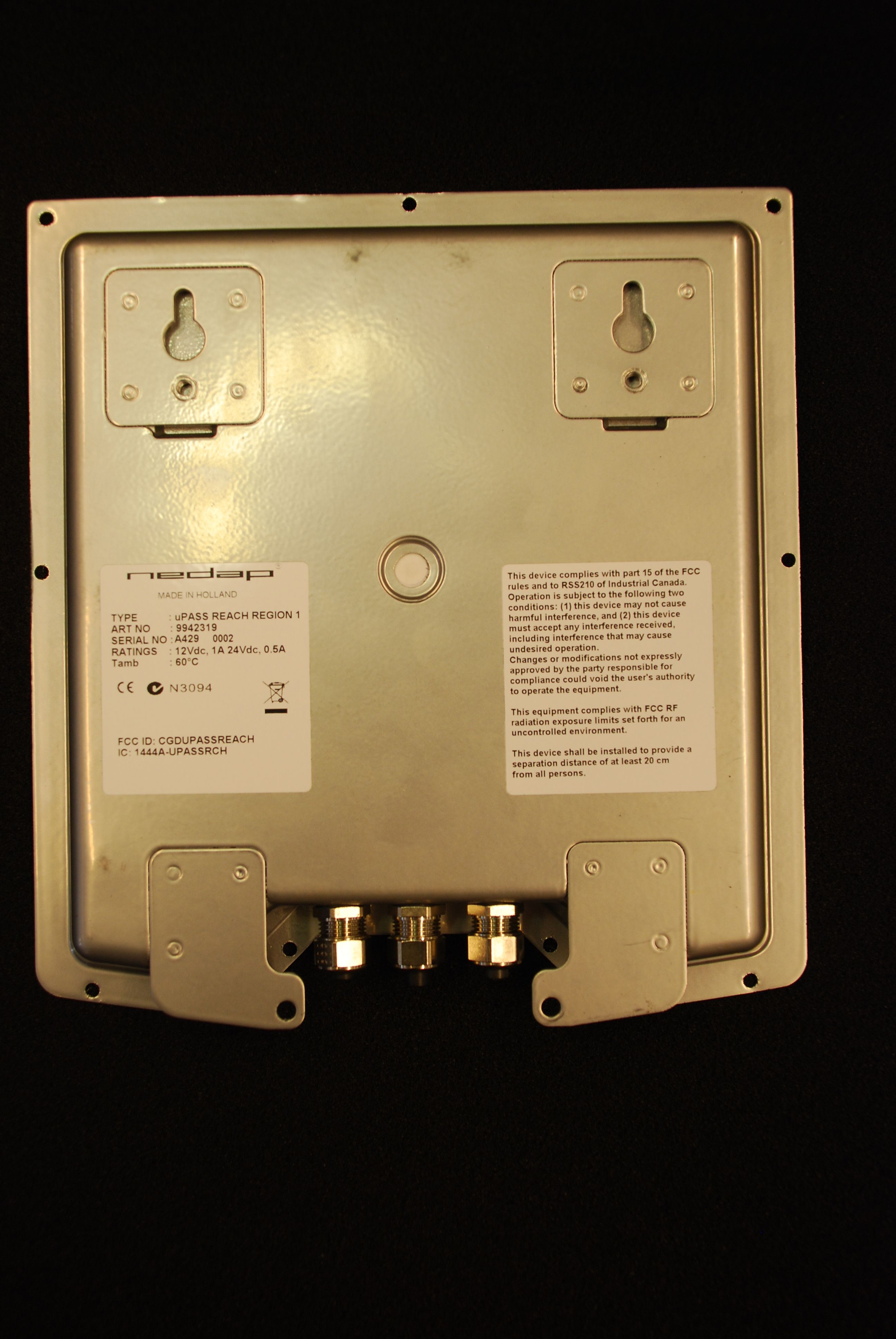
TYPE : uPASS REACH REGION 2&3 ART NO : 9945466 SERIAL NO : RATINGS : 12Vdc, 1A 24Vdc, 0.5A Tamb : 60°C A429 0001 MADE IN HOLLAND FCC ID: CGDUPASSREACH IC: 1444A-UPASSRCH
Internal Photos
Photographs module 20103223301 Internal PHOTOGRAPH 1: PCB TOP VIEW ....................................................................................................................... 2 PHOTOGRAPH 2: METAL HOUSING SEEN FROM INSIDE ........................................................................................ 3 PHOTOGRAPH 3: PCB BOTTOM VIEW ................................................................................................................ 4 PHOTOGRAPH 4: UHF MODULE ...................................................................................................................... 5 PHOTOGRAPH 5: UHF MODULE OPEN .............................................................................................................. 6 PHOTOGRAPH 6: UHF DIPOLE ANTENNA, BOTTOM VIEW.................................................................................... 7 PHOTOGRAPH 7: UHF DIPOLE ANTENNA, TOP VIEW .......................................................................................... 8 Page: 2 of 8 Report number:20103223301 Photograph 1: PCB top view Page: 3 of 8 Report number:20103223301 Photograph 2: metal housing seen from inside Page: 4 of 8 Report number:20103223301 Photograph 3: PCB bottom view Page: 5 of 8 Report number:20103223301 Photograph 4: UHF Module Page: 6 of 8 Report number:20103223301 Photograph 5: UHF module open Page: 7 of 8 Report number:20103223301 Photograph 6: UHF dipole antenna, bottom view Page: 8 of 8 Report number:20103223301 Photograph 7: UHF dipole antenna, top view
RF Exposure Info
Nedap IDEAS R&D 5/17/2010 Declaration on radiation safety standard conformance To whom it may concern: N.V. Nederlandsche Apparaten Fabriek “Nedap” Parallelweg 2 e 7141 DC Groenlo The Netherlands Contact: Ben van Zon; System Engineer Nedap IDEAS R&D [email protected] +31 544 471 710 Declares that the following product Description: UHF EPC Gen2 RFID Reader FCC ID: CGDUPASSREACH Manufacturer: Nedap Brand: uPASS Model: uPASS REACH has a maximum e.i.r.p. of 34.5 dBm, 2818 mW (630 mW, maximum conducted output power plus antenna gain of 6.5 dBi , 4.5x) in the frequency range of 902 – 928 MHz. which means that the power density at 20 cm distance can be calculated as follows : EIRP S = 4*π * R 2 (power density) EIRP 2818 mW S = 4*π * R 2 = 4*π*(20cm) 2 = 0.560 mW/cm 2 (limit = 1.0 mW/cm 2 ) This means that according to OET Bulletin 65 (Edition 97-01), Supplement C (Edition 01-01), the equipment fulfills the requirements on power density for general population/uncontrolled exposure and therefore fulfills the requirements of 47 CFR Part 15.247 (b)(5). Date : 17-05-2010 Name: Ben van Zon Function : System Engineer
Test Report
Radio test report 20103223301 based on: - FCC part 15; subpart C; section 15.247 (ed. 10-1-09); FCC part 15, subpart B, section 15.109 (ed. 10-1-09); IC RSS 210, Annex 8 (issue 7) UHF EPC Gen 2 RFID Reader NEDAP UPASS-REACH Report number: 20103223301 Contents MAIN MODULE .............................................................................................................................................. 3 1 ...... INTRODUCTION ...................................................................................................................................... 3 2 ...... PRODUCT ............................................................................................................................................... 4 3 ...... TEST SCHEDULE ..................................................................................................................................... 4 4 ...... PRODUCT DOCUMENTATION ................................................................................................................... 5 5 ...... OBSERVATIONS AND COMMENTS ........................................................................................................... 5 6 ...... MODIFICATIONS TO THE SAMPLE ............................................................................................................ 5 7 ...... SUMMARY.............................................................................................................................................. 5 8 ...... CONCLUSIONS ........................................................................................................................................ 6 TEST RESULTS MODULE ............................................................................................................................ 7 1 ...... GENERAL INFORMATION ........................................................................................................................ 7 1.1 Equipment information ..................................................................................................................... 7 1.2 Tested channels ................................................................................................................................. 7 2 ...... EMISSION TESTS ..................................................................................................................................... 8 2.1 Carrier frequency separation ............................................................................................................. 8 2.2 Number of hopping frequencies ........................................................................................................ 9 2.3 Average time of occupancy ............................................................................................................. 10 2.4 20 dB bandwidth ............................................................................................................................. 12 2.5 Maximum output power .................................................................................................................. 14 2.6 Band edge compliance .................................................................................................................... 16 2.7 Tx unwanted emissions attenuation (radiated, 0.03 – 1 GHz) ........................................................ 18 2.8 Tx unwanted emissions attenuation (radiated, 1 – 10 GHz) ........................................................... 20 2.9 Tx unwanted emissions in the restricted bands ............................................................................... 22 2.10 Rx unwanted emissions (radiated, 0.03 – 1 GHz) ........................................................................... 23 2.11 Rx unwanted emissions (radiated, > 1GHz) .................................................................................... 25 USED TEST EQUIPMENT MODULE ........................................................................................................ 27 CROSS REFERENCE TABLE ..................................................................................................................... 28 This report comprises of three modules. The total number of pages is: 28 Page: 3 of 28 Main module Report number: 20103223301 Main module 1 Introduction This report contains the result of tests performed by: Telefication B.V. Edisonstraat 12a 6902 PK Zevenaar The Netherlands Telefication complies with the accreditation criteria for test laboratories as laid down in ISO/IEC 17025:2005. The accreditation covers the quality system of the laboratory as well as the specific activities as described in the authorized annex bearing the accreditation number L021 and is granted on 30 November 1990 by the Dutch Council For Accreditation (RvA: Raad voor Accreditatie). The contents of this test report, if reproduced, shall be copied in full, unless special consent in writing for reproduction in part is granted by Telefication. Copyright of this test report is reserved to Telefication. Ordering party: Company name : N.V. Nederlandsche Apparatenfabriek Nedap Address : 2e Parallelweg Zipcode : 7141 DC City/town : Groenlo Country : The Netherlands Date of order : 25 February 2010 Page: 4 of 28 Main module Report number: 20103223301 2 Product A sample of the following product was submitted for testing: Product description : UHF EPC Gen 2 RFID Reader Manufacturer : N.V. Nederlandsche Apparatenfabriek Nedap Trade mark : NEDAP Type designation : UPASS-REACH FCC ID : CGDUPASS-REACH IC ID : 1444A-UPASSRCH Hardware version : A02 Serial number : -- Firmware release : 2.04 3 Test schedule Tests are carried out in accordance with the specification detailed in chapter 7 “Summary” of this report. Tests are carried out at the following location: Telefication, Zevenaar The sample of the product is received on: 19 April 2010 Tests are carried out between: 19 April 2010 and 12 May 2010 Pag…
Text truncated - open the document above for the full version.
Test Setup Photos
Photographs module 20103223301 Test set up PHOTOGRAPH 1: RADIATED EMISSIONS TEST SETUP (0.03 – 1 GHZ) ................................................................... 2 PHOTOGRAPH 2: TEST SETUP RADIATED EMISSIONS (1 - 13 GHZ) ...................................................................... 3 Page: 2 of 3 Report number:20103223301 Photograph 1: Radiated emissions test setup (0.03 – 1 GHz) Page: 3 of 3 Report number:20103223301 Photograph 2: Test setup radiated emissions (1 - 13 GHz)
Contact Information
Applicant
Reinold Hubers(Approbation Officer)
Technical Contact
Test Firm
Kiwa Nederland B.V.Willem Jong
[email protected]+31 889983621
Technical Specifications
| # | Rule Parts | Frequency Range | Power Output |
|---|---|---|---|
| 1 | 15C | 902.7 MHz - 927.2 MHz | 180.00 mW |
Other Applications from Nedap N. V.
CGDVP1004B
Jan 25, 2021VP1004-B System
Equipment Class
DCD - Part 15 Low Power Transmitter Below 1705 kHz
CGDFERPH
Dec 15, 2020SMARTTAG EAR
Equipment Class
DXX - Part 15 Low Power Communication Device Transmitter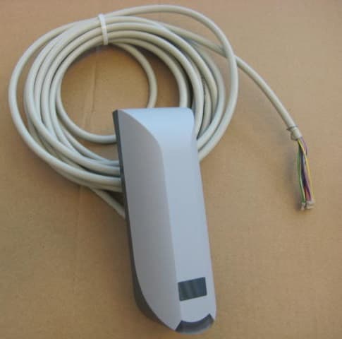
CGDNVR2001
Dec 01, 2020Reader for 120 kHz and 13.56 MHz cards and also NFC, QR and BT
Equipment Class
DCD - Part 15 Low Power Transmitter Below 1705 kHz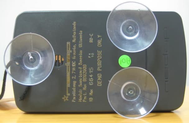
CGDBOOSTER11
Nov 30, 2020Long-range vehicle and driver identification tag
Equipment Class
DSR - Part 15 Remote Control/Security Device Transceiver
CGDLD4KW
Jul 15, 20204kW Electronic Lamp Driver
Equipment Class
DTS - Digital Transmission System