CGDVELOS3RFID Reader for Livestock
Nedap N. V.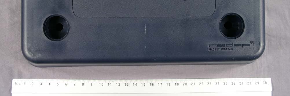
Click to zoom
Application Details
- Equipment Class
- DCD - Part 15 Low Power Transmitter Below 1705 kHz
- Date of Grant
- Apr 24, 2009
- Application Purpose
- Original Equipment
- Date of Application
- Apr 23, 2009
- Equipment Note
- RFID Reader for Livestock
- Frequency Range
- 0.13400000 - 0.13400000
- Company
- Nedap N. V.
- Country
- Netherlands
Documents & Files
Document Text
Text extracted from the exhibit documents filed with the FCC. Open a document above to read the original.
Users Manual
Service manual For installation, operation and service ISO Reader Solid (CAN) VP1101 March 2009 / Manual version 1.0 VP1101-200PM-00 ISO Reader Solid (CAN) Manual version 1.0 Version overview Manual version 1.0 / 3-2009 First release This information is furnished for guidance, and with no guarantee as to its accuracy or completeness; its publication conveys no license under any patent or other right, nor does the publisher assume liability for any consequence of its use; specifications and availability of goods mentioned in it are subject to change without notice; it is not to be reproduced in any way, in whole or in part, without the written consent of the publisher. © Nedap N.V., AGRI P.O. Box 104 NL-7140 AC GROENLO The Netherlands VP1101-200PM-00 ISO Reader Solid (CAN) Manual version 1.0 VP1101 ISO Reader Solid CAN Contents 1 Introduction 1 2 Description and functioning 1 3 Safety 1 4 Installation 2 4.1 Mounting 2 4.2 Connections 2 5 Adjustments 2 6 Trouble shooting 2 7 Maintenance, cleaning and disposal 2 Appendix A: Specifications 3 VP1101-200PM-00 ISO Reader Solid (CAN) Manual version 1.0 VP1101-200PM-00 ISO Reader Solid (CAN) Manual version 1.0 / Page 1 Preface This manual is part of the service documentation for Nedap Velos. Reference is also made to other manuals that are part of the Nedap Velos documentation. For an overview of available Nedap Velos manuals see the manual “Nedap Velos General Description”, or visit the Nedap Agri website www.nedap-agri.com. 1 Introduction The Velos VP1001 is a Velos component that is used to identify RFID tags on animals. The VP1101 is installed close to the spot where identification is required, for example on the animal feeder. 2 Description and functioning A VP1101 is connected to the CAN-bus and can identify tags on ISO frequency 134.2 kHz. There are two types, FDX/HDX or FDX only. 3 Safety Installation and service only by trained personnel. Always turn off the main power when working on the electrical installation. Compliance statement (part 15.19) This device complies with part 15 of the FCC Rules and to RSS210 of Industry Canada. Operation is subject to the following two conditions: (1) this device may not cause harmful interference, and (2) this device must accept any interference received, including interference that may cause undesired operation. Changes or modifications not expressly approved by the party responsible for compliance could void the user’s authority to operate the equipment. Warning (part 15.21) Changes or modifications not expressly approved by the party responsible for compliance could void the user’s authority to operate the equipment. VP1101-200PM-00 ISO Reader Solid (CAN) Manual version 1.0 / Page 2 4 Installation 4.1 Mounting See the relevant equipment manual relating to where the VP1101 is to be installed. (e.g. feeder). 4.2 Connections Details VP1101 wiring Brown + Input voltage 25 VDC, +20% -20% White - Minus Green C H CAN high Yellow C L CAN low Shield Shielding of CAN-bus cable Grey ~ Synchronization (antenna) Pink ~ Synchronization (antenna) 5 Adjustments A VP1101 is pre-tuned and ready for use. No antenna adjustments required because of automatic fine tuning. 6 Trouble shooting Errors / malfunctioning are indicated at the controlling computer. 7 Maintenance, cleaning and disposal Maintenance No regular maintenance required. Software update By the CAN bus there is a possibility to update the software. Cleaning A VP1101 can be cleaned with water and sponge. Avoid (aggressive) cleaning liquids. Disposal Discard according to the regulations prevailing at the time of disposal VP1101-200PM-00 ISO Reader Solid (CAN) Manual version 1.0 / Page 3 Appendix A: Specifications Specifications VP 1101 Dimensions 2850 x 1700 x 45 mm LxWxH CAN CAN-bus communication 125 kBit Power Input voltage 25 VDC, +20% -20% Power consumption 200 mA with antenna switched on Protected against reverse connection power supply Software Downloadable by the CAN network Antennas Internal fixed antenna Detection distance Depending on used tags Synchronization Synchronization according to ISO 11785, ISO 24631-7 Environment Temperature: Operating: -10 – 50 °C, Storage: -25 – 70 °C Relative humidity: 10 – 93% non condensing IP class IP 65. Always use a NEDAP power supply. The Nedap guarantee-regulations are only valid when is installed as indicated in this manual. Install data cables at a safe distance from (high) powered cables More information For more detailed information contact your local Nedap supplier or check the internet site.
Cover Letter(s)
TÜV Rheinland EPS B.V. Smidshornerweg 18 P.O. Box 15 9822 ZG Niekerk The Netherlands www.tuv-eps.com T +31 594 505005 F +31 594 504804 E [email protected] Subject Request for confidentiality Date March 06, 2009 Our reference 09010504.B02 Your reference -- Page 1 of 1 Our General Terms and Conditions, as filed at the Chamber of Commerce in Groningen, are applicable to all orders given to TÜV Rheinland EPS B.V. TÜV Rheinland EPS B.V. is registered at the Chamber of Commerce in Groningen with no. 27247331. TUEV and TUV are registered trademarks. Utilisation and application requires prior approval. Return address: P.O. Box 15, 9822 ZG Niekerk, The Netherlands ATCB Attn.: Mrs. M. Bosley Certification Department 6731 Whittier Avenue, Suite C110 McLean, Virginia 22101 USA Dear Mrs. Bosley, Pursuant to section 0.457(d)(2)(i) and Section 0.459 of the FCC rules we herewith request the following exhibits, related to this application for FCC ID : CGDVELOS3 Brand : Nedap Model : VP1101 to be withheld from public inspection and to be kept confidential. The contents of these exhibits may not be disclosed to other parties than N.V. Nederlandsche Apparatenfabriek "Nedap" and TÜV Rheinland EPS B.V.: 1. Bill of materials 2. Circuit diagram 3. Block diagram 4. Theory of operation (technical description) The reason for this request for confidentiality is that the information contained in the exhibits as listed above has been classified as company confidential. Disclosure of any portion of this information to other parties would cause substantial competitive harm. Best regards, TÜV Rheinland EPS B.V. R. van der Meer Test Engineer
Cover Letter(s)
TÜV Rheinland EPS B.V. Smidshornerweg 18 P.O. Box 15 9822 ZG Niekerk The Netherlands www.tuv-eps.com T +31 594 505005 F +31 594 504804 E [email protected] Subject Reply to ATCB comments Date April 14, 2009. Our reference 17_CGDVELOS3_ReplyToAT CBcomments Your reference -- Page 1 of 5 Our General Terms and Conditions, as filed at the Chamber of Commerce in Groningen, are applicable to all orders given to TÜV Rheinland EPS B.V. TÜV Rheinland EPS B.V. is registered at the Chamber of Commerce in Groningen with no. 27247331. ® TÜV, TUEV and TUV are register ed trademarks. Utilisation and app lication requires prior approval. Return address: P.O. Box 15, 9822 ZG Niekerk, The Netherlands ATCB Attn.: Mrs. M. Bosley Certification Department 6731 Whittier Avenue, Suite C110 McLean, Virginia 22101 USA Dear Mrs. Bosley, Related to your comments based on our request for certification for the following product,: FCC ID : CGDVELOS3 Brand : Nedap Model : VP1101 Description : A proximity tag reader operating on 134 kHz. We would like to provide you with the following information: Question 1 : The test configuration for measuring emissions from this 134 kHz transmitter is questionable. The configuration appears to contain three separate 134 kHz transmitters on the turntable. Placing so many cases and wires in such close proximity to a 134 kHz transmitter may reduce the radiated emissions from this transmitter. There is nothing wrong with the test configuration and the radiated emission test results between 30 and 1000 MHz for the digital emissions. However, you must confirm that the test results provided below 30 MHz are representative of the 134 kHz transmitter under test. To do so, I suggest that you place only the EUT on the turntable, place the loop antenna 3 (or 10 meters) away and place the accessories to the EUT another 3 meters (10 would be better) away from the turntable (all in a straight line) to ensure that the accessories are not affecting the radiated emission test results on the 134 kHz transmitter. (See attachment entitled “test diagram.pdf”). Then measure the radiated emissions below 30 MHz from the EUT while rotating the turntable, rotating the loop antenna and moving the EUT through 3 orthogonal axes. If there is no change in results, please document that you have tested the transmitter in this manner. If the results change, please provide new radiated emissions test data below 30 MHz. I note that this request is in line with the ATCB response attached (See attachment entitled “ATCB Reply on This System.pdf.” Answer 1: The idea was to test the system in whole to simulate worst case situation and if proven to be within limits it can be assumed that the transmitter solely would comply. I retested the transmitter together with the VP8001-2 and VP2001 (minimally needed for normal operation) on the test table, so I was able to still turn the table around. With these minimal parts around no influence on the transmitter is expected nor is it seen in the results. The measurement results did not differ from the results noted in the test report. The re-test was only done Date April 14, 2009 Our reference 17_CGDVELOS3_ReplyToAT CBcomments Your reference -- Page 2 of 5 at 3m and with the common procedure, which you also suggested. See the uploaded document: 14_CGDVELOS3_Rev01_Photo Report_Testsetup.pdf for updated photograph. Question 2: The tested system details in Section 1.3 of the test report do not agree with the block diagram and interface cable list in Section 1.3.1 of the test report. For example, in Section 1.3, the transmitter being approved in this application is called EUT1 but in Section 1.3.1 it is called the VP1101. There is no consistency between these two sections. The interface cable list above the block diagram is missing information or also has inconsistencies. There is no information on the cable connecting the VP1007 with the mini antenna to the VP1007 that acts strictly as an I/O module. There is also no information on the cables that connect the VPU to VP2001. In the list of cables, cable 2 connects the VPU to the VP1101 (the transmitter being approved in this application). Cable 8 also connects the VP1101 to the VP8001 (Is the VP8001 the VPU?) I suggest the block diagram be relabeled to agree with the names EUT1 through EUT 10 and AUX given in Section 1.3 of the test report. Also supply all the information on the interconnecting cables and possibly label the individual cables so the references are clear. Answer 2 : Corrected, see uploaded document: 13_CGDVELOS3_fcc01_Rev01_Test report.pdf Question 3 : Please provide the resolution bandwidth (RBW) of the measuring instrument during AC line conducted emissions testing. Answer 3 : Corrected and stated in Note 2 of Table 5 on page 14 of revised test report, see uploaded document: 13_CGDVELOS3_fcc01_Rev01_Test report.pdf. Question 4: Please provide the detector function and RBW of the measuring instrument used during radiated emission measurements reported in Table 2 (except the frequency bands 9 to 90 and 110 to 490 kHz). Answer 4 : Corrected and stated in Notes 2 and 3 of Table 2 on page 12 of revised test report, see uploaded document: 13_CGDVELOS3_fcc01_Rev01_Test report.pdf. Question 5: In Table 2 of the test report, do the measured results already include the antenna factor and cable loss or do they need to be added to achieve the measured level? If they are already included, just confirm that they are. If these factors are not included in the measured level, please provide a sample calculation of the final field strength using the attenuation factor and formulas mentioned in Appendix 1 of the test report. Answer 5 : Corrected in Note 1 of Table 2 and Appendix 1 of revised test report, see uploaded document: 13_CGDVELOS3_fcc01_Rev01_Test report.pdf. Date April 14, 2009 Our reference 17_CGDVELOS3_ReplyToAT CBcomments Your reference -- Page 3 of 5 Question 6: The FCC ID label for this device does not contain the statement req…
Text truncated - open the document above for the full version.
Cover Letter(s)
TÜV Rheinland EPS B.V. Smidshornerweg 18 P.O. Box 15 9822 ZG Niekerk The Netherlands www.tuv-eps.com T +31 594 505005 F +31 594 504804 E [email protected] Subject Antenna info Date March 06,2009 Our reference 09010504.B05 Your reference -- Page 1 of 1 Our General Terms and Conditions, as filed at the Chamber of Commerce in Groningen, are applicable to all orders given to TÜV Rheinland EPS B.V. TÜV Rheinland EPS B.V. is registered at the Chamber of Commerce in Groningen with no. 27247331. ® TÜV, TUEV and TUV are registered trademarks. Utilisation and application requires prior approval. Return address: P.O. Box 15, 9822 ZG Niekerk, The Netherlands ATCB Attn.: Mrs. M. Bosley Certification Department 6731 Whittier Avenue, Suite C110 McLean, Virginia 22101 USA Dear Mrs. Bosley, On behalf of our customer N.V. Nederlandsche Apparatenfabriek “Nedap” B.V, we hereby declare that the antenna of the following device: FCC ID: CGDVELOS3 Manufacturer: N.V. Nederlandsche Apparatenfabriek “Nedap” B.V Brand: Nedap Model: VP1101 Description: an inductive proximity tag reader, operating on 134 kHz Is part of the device. See for details the photographs of the interior of the device (exibit 09). Peak gain : not applicable Material : Cupper wire Description : the antenna is a loop antenna made of several windings of cupper- wire acting like a coil. It’s intended to transform AC-current into an electro magnetic field. The cupper-wires ends are soldered on the PCB, so there is no antennaconnector. The antenna is in the same housing as the PCB but is not placed on the PCB. The housing of the VP1101 is sealed and it is not possible to exchange antenna’s. Best regards, TÜV Rheinland EPS B.V. R. van der Meer Test Engineer
External Photos
Testing and certification of, consultancy and research concerning, electronic and electric appliances, systems, installations and telecommunication systems TÜV Rheinland EPS B.V. P.O. Box 15 9822 ZG Niekerk (NL) Smidshornerweg 18 9822 TL Niekerk (NL) Telephone: +31 594 505005 Telefax: +31 594 504804 Internet: www.tuv-eps.com E-mail: [email protected] Project number: 09010504_CGDVELOS3.p01 Page 1 of 7 PHOTOGRAPHS OF THE EXTERIOR OF AN INDUCTIVE PROXIMITY TAG READER OPERATING ON 134.2 KHZ, BRAND NEDAP, MODEL VP1101 FCC listed Industry Canada VCCI Registered R&TTE, LVD, EMC Notified Body : : : : 90828 2932G-1 R-1518, C-1598 1856 Description of EUT: Manufacturer: Brand mark: Model: 47 CFR Part 15 (2008-07) N.V. Nederlandse Apparatenfabriek “Nedap” Nedap VP1101 Project number: 09010504_CGDCVELOS3.p01 Page 2 of 7 Description of test item Test item : Inductive tag reader operating on 134 kHz Manufacturer : N.V. Nederlandsche Apparatenfabriek “Nedap” Brand : Nedap Model(s) : VP1101 Serial number(s) : X126 0002 Revision : n.a. Recection date : January 27, 2009 Applicant information Applicant's representative : Mr. J.A.M. Hulshof Company : N.V. Nederlandsche Apparatenfabriek “Nedap” Address : Parallelweg 2 Postal code : 7141 DC City : Groenlo Country : The Netherlands Telephone number : +31 544 471 162 Telefax number : +31 544 463 475 Description of EUT: Manufacturer: Brand mark: Model: 47 CFR Part 15 (2008-07) N.V. Nederlandse Apparatenfabriek “Nedap” Nedap VP1101 Project number: 09010504_CGDCVELOS3.p01 Page 3 of 7 Table of contents 1 PHOTOGRAPHS OF THE EQUIPMENT. .......................................................................................................................... 4 1.1 EXTERNAL VIEW. ................................................................................................................................................................ 4 1.1.1 Front view ................................................................................................................................................................. 4 1.1.2 Front view, cable included ..................................................................................................................................... 5 1.1.3 Rear view .................................................................................................................................................................. 6 1.1.4 Rear view, including cable ..................................................................................................................................... 7 Description of EUT: Manufacturer: Brand mark: Model: 47 CFR Part 15 (2008-07) N.V. Nederlandse Apparatenfabriek “Nedap” Nedap VP1101 Project number: 09010504_CGDCVELOS3.p01 Page 4 of 7 1 Photographs of the equipment. 1.1 External view. 1.1.1 Front view Front view Description of EUT: Manufacturer: Brand mark: Model: 47 CFR Part 15 (2008-07) N.V. Nederlandse Apparatenfabriek “Nedap” Nedap VP1101 Project number: 09010504_CGDCVELOS3.p01 Page 5 of 7 1.1.2 Front view, cable included Description of EUT: Manufacturer: Brand mark: Model: 47 CFR Part 15 (2008-07) N.V. Nederlandse Apparatenfabriek “Nedap” Nedap VP1101 Project number: 09010504_CGDCVELOS3.p01 Page 6 of 7 1.1.3 Rear view Description of EUT: Manufacturer: Brand mark: Model: 47 CFR Part 15 (2008-07) N.V. Nederlandse Apparatenfabriek “Nedap” Nedap VP1101 Project number: 09010504_CGDCVELOS3.p01 Page 7 of 7 1.1.4 Rear view, including cable
Test Report
Testing and certification of, consultancy and research concerning, electronic and electric appliances, systems, installations and telecommunication systems TÜV Rheinland EPS B.V. P.O. Box 15 9822 ZG Niekerk (NL) Smidshornerweg 18 9822 TL Niekerk (NL) Telephone: +31 594 505005 Telefax: +31 594 504804 E-mail: [email protected] Web: www.tuv-eps.com Project number: 09010504.CGDVELOS3.fcc01_Rev01 Page 1 of 1 TEST REPORT CONCERNING THE COMPLIANCE OF A 134 KHZ INDUCTIVE PROXIMITY TAG READER, BRAND NEDAP, MODEL VP1101 WITH 47 CFR PART 15 (JULY 10, 2008). FCC listed Industry Canada VCCI Registered R&TTE, LVD, EMC Notified Body : : : : 90828 2932G-1 R-1518, C-1598 1856 Test specification(s): Description of EUT: Manufacturer: Brand mark: Model: FCC ID: FCC Part 15 134 kHz Inductive proximity Tag Reader N.V. Nederlandsche Apparatenfabriek “Nedap” Nedap VP1101 CGDVELOS3 Project number : 09010504.CGDVELOS3.fcc01_Rev01 Page 2 of 2 MEASUREMENT/TECHNICAL REPORT Nedap N.V. Model : VP1101 FCC ID: CGDVELOS3 April 14, 2009 This report concerns: Original grant/certification Class 2 change Verification Equipment type: 134 kHz Inductive proximity tag reader Deferred grant requested per 47 CFR 0.457(d)(1)(ii) ? Yes No n.a. Report prepared by: Name : Richard van der Meer Company name : TÜV Rheinland EPS B.V. Address : Smidshornerweg 18 Postal code/city : 9822 TL Niekerk Mailing address : P.O. Box 15 Postal code/city : 9822 ZG Niekerk Country : The Netherlands Telephone number : + 31 594 505 005 Telefax number : + 31 594 504 804 E-mail : [email protected] The data taken for this test and report herein was done in accordance with 47 CFR Part 15 (july 10, 2008) and the measurement procedures of ANSI C63.4-2003. TÜV Rheinland EPS B.V. at Niekerk, The Netherlands, certifies that the data is accurate and contains a true representation of the emission profile of the Equipment Under Test (EUT) on the date of the test as noted in the test report. I have reviewed the test report and find it to be an accurate description of the test(s) performed and the EUT so tested. Date: April 14, 2009 Signature: O. Hoekstra Senior Engineer Telecom TÜV Rheinland EPS B.V. Test specification(s): Description of EUT: Manufacturer: Brand mark: Model: FCC ID: FCC Part 15 134 kHz Inductive proximity Tag Reader N.V. Nederlandsche Apparatenfabriek “Nedap” Nedap VP1101 CGDVELOS3 Project number : 09010504.CGDVELOS3.fcc01_Rev01 Page 3 of 3 Description of test item Test item : Inductive proximity tag reader, operating on 134.2 kHz, brand Nedap Manufacturer : N.V. Nederlandsche Apparatenfabriek “Nedap” Brand : Nedap Model(s) : VP1101 Serial number(s) : X126 0002 Revision : n.a. Applicant information Applicant's representative : Mr. J. Hulshof Company : N.V. Nederlandsche Apparatenfabriek “Nedap” Address : Parallelweg 2 Postal code : 7141 DC City : Groenlo Country : The Netherlands Telephone number : +31 544 471 444 Telefax number : +31 544 466 839 Test(s) performed Location : Niekerk Test(s) started : January 28, 2009 Test(s) completed : February 03, 2009 Purpose of test(s) : Equipment Authorization (Original grant/certification) Test specification(s) : 47 CFR Part 15 (July 10, 2008) Test engineer(s) : R. van der Meer Report written by : R. van der Meer Report date : April 14, 2009 This report is in conformity with NEN-EN-ISO/IEC 17025: 2005 This report shall not be reproduced, except in full, without the written permission of TÜV Rheinland EPS B.V. The test results relate only to the item(s) tested. Test specification(s): Description of EUT: Manufacturer: Brand mark: Model: FCC ID: FCC Part 15 134 kHz Inductive proximity Tag Reader N.V. Nederlandsche Apparatenfabriek “Nedap” Nedap VP1101 CGDVELOS3 Project number : 09010504.CGDVELOS3.fcc01_Rev01 Page 4 of 4 Table of contents 1 General information. .............................................................................................................................................. 5 1.1 Product description. ........................................................................................................................................ 5 1.1.1 Introduction. ............................................................................................................................................ 5 1.2 Related submittal(s) and/or Grant(s). ............................................................................................................. 5 1.2.1 General. .................................................................................................................................................. 5 1.3 Tested system details. .................................................................................................................................... 5 1.3.1 Description of input and output ports. ..................................................................................................... 8 1.4 Test methodology. .......................................................................................................................................... 9 1.5 Test facility. .................................................................................................................................................... 9 1.6 Test conditions. .............................................................................................................................................. 9 2 System test configuration. ................................................................................................................................... 10 2.1 Justification. .................................................................................................................................................. 10 2.2 EUT mode of operation. ............................................................................................................................... 10 2.3 Special accessories. ..................................................................................…
Text truncated - open the document above for the full version.
Test Setup Photos
Testing and certification of, consultancy and research concerning, electronic and electric appliances, systems, installations and telecommunication systems TÜV Rheinland EPS B.V. P.O. Box 15 9822 ZG Niekerk (NL) Smidshornerweg 18 9822 TL Niekerk (NL) Telephone: +31 594 505005 Telefax: +31 594 504804 Internet: www.tuv-eps.com E-mail: [email protected] Project number: 09010504.p03_Rev01 Page 1 of 1 PHOTOGRAPHS OF THE TESTSETUP OF A INDUCTIVE TAG READER OPERATING ON 134KHZ, BRAND NEDAP, MODEL VP1101. FCC listed Industry Canada VCCI Registered R&TTE, LVD, EMC Notified Body : : : : 90828 2932G-1 R-1518, C-1598 1856 Description of EUT: Manufacturer: Brand mark: Model: 47 CFR Part 15 (2008-07) N.V. Nederlandse Apparatenfabriek “Nedap” Nedap VP1101 Project number: 09010504.p03_Rev01 Page 2 of 2 Description of test item Test item : Inductive tag reader operating on 134 kHz Manufacturer : N.V. Nederlandsche Apparatenfabriek “Nedap” Brand : Nedap Model(s) : VP1101 Serial number(s) : X126 0002 Revision : Not applicable Applicant information Applicant's representative : Mr. J.A.M. Hulshof Company : N.V. Nederlandsche Apparatenfabriek “Nedap” Address : Parallelweg 2 Postal code : 7141 DC City : Groenlo Country : The Netherlands Telephone number : +31 544 471 162 Telefax number : +31 544 463 475 Description of EUT: Manufacturer: Brand mark: Model: 47 CFR Part 15 (2008-07) N.V. Nederlandse Apparatenfabriek “Nedap” Nedap VP1101 Project number: 09010504.p03_Rev01 Page 3 of 3 Table of contents 1 PHOTOGRAPHS OF THE TESTSETUP. ....................................................................................................................... 4 1.1 RADIATED EMISSIONS..................................................................................................................................................... 4 1.1.1 Radiated emissions H-field @ 3m ..................................................................................................................... 4 1.1.2 Radiated emissions H-field @ 10m ................................................................................................................... 5 1.1.3 Radiated emissions E-field @3m ...................................................................................................................... 6 1.2 CONDUCTED EMISSIONS ................................................................................................................................................ 7 1.2.1 Conducted emissions testsetup overview ........................................................................................................ 7 1.2.2 Conducted emissions EUT detail ...................................................................................................................... 8 1.3 FREQUENCY/CARRIER STABILITY ................................................................................................................................... 9 Description of EUT: Manufacturer: Brand mark: Model: 47 CFR Part 15 (2008-07) N.V. Nederlandse Apparatenfabriek “Nedap” Nedap VP1101 Project number: 09010504.p03_Rev01 Page 4 of 4 1 Photographs of the testsetup. 1.1 Radiated emissions. 1.1.1 Radiated emissions H-field @ 3m Description of EUT: Manufacturer: Brand mark: Model: 47 CFR Part 15 (2008-07) N.V. Nederlandse Apparatenfabriek “Nedap” Nedap VP1101 Project number: 09010504.p03_Rev01 Page 5 of 5 1.1.2 Radiated emissions H-field @ 10m Description of EUT: Manufacturer: Brand mark: Model: 47 CFR Part 15 (2008-07) N.V. Nederlandse Apparatenfabriek “Nedap” Nedap VP1101 Project number: 09010504.p03_Rev01 Page 6 of 6 1.1.3 Radiated emissions E-field @3m Description of EUT: Manufacturer: Brand mark: Model: 47 CFR Part 15 (2008-07) N.V. Nederlandse Apparatenfabriek “Nedap” Nedap VP1101 Project number: 09010504.p03_Rev01 Page 7 of 7 1.2 Conducted emissions 1.2.1 Conducted emissions testsetup overview Description of EUT: Manufacturer: Brand mark: Model: 47 CFR Part 15 (2008-07) N.V. Nederlandse Apparatenfabriek “Nedap” Nedap VP1101 Project number: 09010504.p03_Rev01 Page 8 of 8 1.2.2 Conducted emissions EUT detail Description of EUT: Manufacturer: Brand mark: Model: 47 CFR Part 15 (2008-07) N.V. Nederlandse Apparatenfabriek “Nedap” Nedap VP1101 Project number: 09010504.p03_Rev01 Page 9 of 9 1.3 Frequency/Carrier stability 1.3.1. Frequency/Carrier stability testsetup overview Description of EUT: Manufacturer: Brand mark: Model: 47 CFR Part 15 (2008-07) N.V. Nederlandse Apparatenfabriek “Nedap” Nedap VP1101 Project number: 09010504.p03_Rev01 Page 10 of 10 1.3.2 Frequency/Carrier stability, testsetup detail
Contact Information
Applicant
Reinold Hubers(Approbation Officer)
Technical Contact
TUV Rheinland EPS BVRichard van der Meer
[email protected]+31-594-505-005
Smidshornerweg 18 · Niekerk · Netherlands
Non-Technical Contact
Nedap BVJacques Hulshof
[email protected]+31-544-471-4444
Test Firm
TUV Rheinland Nederland B.V.Wiebe Boekema
Technical Specifications
| # | Rule Parts | Frequency Range | Power Output |
|---|---|---|---|
| 1 | 15C | 0.134 MHz - 0.134 MHz | - |
Other Applications from Nedap N. V.
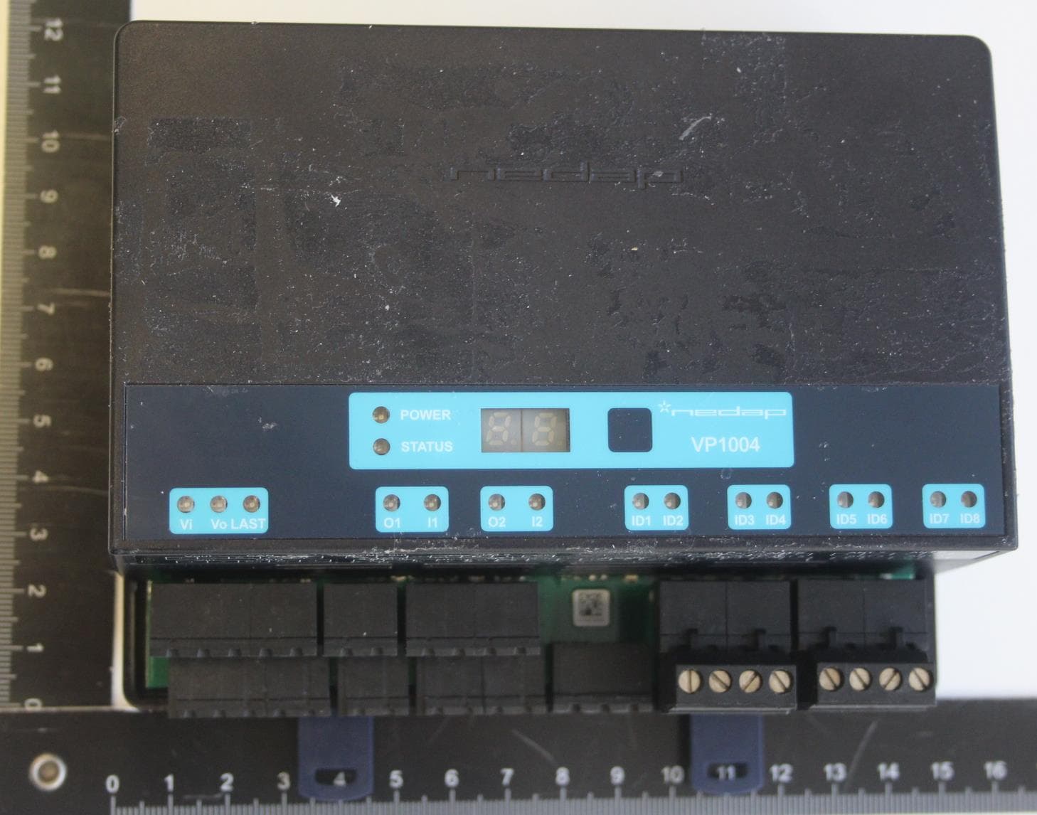
CGDVP1004B
Jan 25, 2021VP1004-B System
Equipment Class
DCD - Part 15 Low Power Transmitter Below 1705 kHz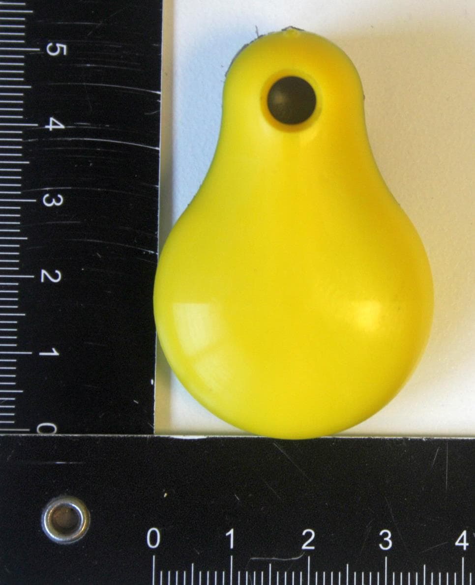
CGDFERPH
Dec 15, 2020SMARTTAG EAR
Equipment Class
DXX - Part 15 Low Power Communication Device Transmitter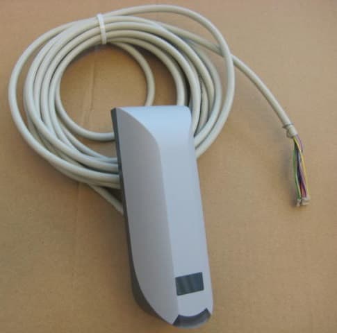
CGDNVR2001
Dec 01, 2020Reader for 120 kHz and 13.56 MHz cards and also NFC, QR and BT
Equipment Class
DCD - Part 15 Low Power Transmitter Below 1705 kHz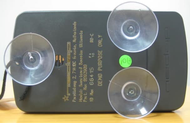
CGDBOOSTER11
Nov 30, 2020Long-range vehicle and driver identification tag
Equipment Class
DSR - Part 15 Remote Control/Security Device Transceiver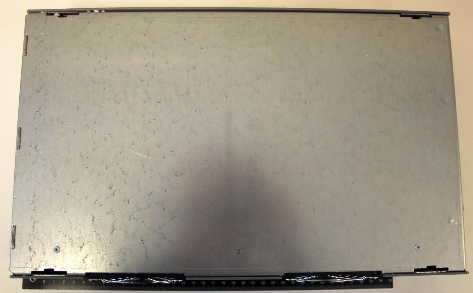
CGDLD4KW
Jul 15, 20204kW Electronic Lamp Driver
Equipment Class
DTS - Digital Transmission System