CGGAA3RCR-50, RCR-PET, RCR-C
UTC Fire & Security B.V.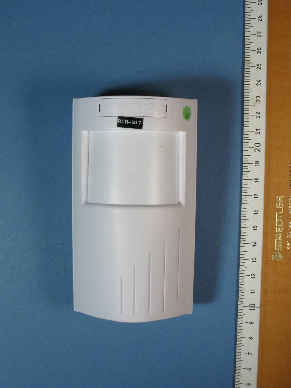
Click to zoom
Application Details
- Equipment Class
- DXX - Part 15 Low Power Communication Device Transmitter
- Date of Grant
- Jun 20, 2011
- Application Purpose
- Original Equipment
- Date of Application
- Jun 19, 2011
- Equipment Note
- RCR-50, RCR-PET, RCR-C
- Frequency Range
- 5789.00000000 - 5789.00000000
- Company
- UTC Fire & Security B.V.
- Country
- Netherlands
Documents & Files
Document Text
Text extracted from the exhibit documents filed with the FCC. Open a document above to read the original.
Users Manual
1 PrecisionLine RCR-A/RCR-C Description PrecisionLine dual technology sensors combine range-controlled radar (RCR) technology with a passive infrared (PIR) system to increase false alarm immunity by allowing them to sense human- sized objects within a specified range. Both the RCR and PIR systems must be triggered to set off an alarm, unless in stealth mode (radar-only). The detector is designed to use a 12VDC power supply provided by a UL Listed alarm control panel. Features The detector provides the following features: •Stealth Mode (radar only) - Internal jumper allows you to disable the PIR, and use the radar only to detect intruders faster. This mode can be used for covert installations (mounted behind walls). •Selectable range up to 35 feet (10.7m) - Internal jumper allows radar range selection to optimize coverage. •LED indicator - A multi-color LED provides detector status. •Tamper switch (RCR-C only) - Activated when the pins on the circuit board are removed from the terminal sockets on the base. Parts The following parts are included with the detector: •RCR detector •1 screw to join the case halves •3 factory-installed jumpers Selecting a Location for the Detector The detector can be mounted in a corner or on a flat wall. Use the following guidelines to determine the best location to install the detector: •Mount the detector so the expected movement of an intruder is across the detection pattern. See Figure 1. •Mount the detector on a stable surface 7 to 9 feet (2.1 to 2.7m) high. •DO NOT mount the detector within 2 feet (0.6m) of any metallic objects or within 5 feet (1.5m) of any florescent lights. •DO NOT place any objects in front of the detector that may prevent a clear line of sight. Not applicable in High Security Mode (radar only). •Avoid locations that expose the detector to possible false alarm sources such as: – Moving or vibrating objects (fans, pulleys, conveyor belts) – Electronic fields (electric motors, high voltage equipment) – Water spray or corrosive environments – Heat sources in the field of view (heaters, radiators) – Windows in the field of view – Strong air drafts on the detector (fans, air conditioners) •When installing multiple detectors: – DO NOT mount detectors facing each other. – Mount them at least 20 feet (6.1m) apart. – Use shorter range settings to avoid overlapping radar coverage. – Mounting sensors back to back is not recommended, but if an application requires such mounting, use the 9-foot (2.7m) range, mount at least 1foot (0.3m) apart, and walk test the installation to ensure proper operation. SPR TMPR TMPR NO COM Figure 2. Detector (exploded) Figure 1. RCR and PIR Coverage Patterns 90° Radar Viewing Area PIR Viewing Area Top View Side View 35’ (10.7m) 35’ (10.7m) 27’ (8.2m) 27’ (8.2m) 18’ (5.5m) 18’ (5.5m) 9’ (2.7m) 9’ (2.7m) 0’ 0’ 35’ (10.7m) 27’ (8.2m) 18’ (5.5m) 9’ (2.7m) 6.9’ (2.1m) PrecisionLine Dual Technology Motion Sensor Models:RCR-A (Form A) RCR-C (Form C) Installation Instructions 2 PrecisionLine RCR-A/RCR-C Installing the Detector All wiring must conform to National Electric Code (NEC) and/or local codes having jurisdiction. Important: DO NOT use this device for safety interlock applications. Use the following steps to install the detector: 1. Run the security system wiring to the detector location. 2. To remove the front cover/electronic module, press down on the lever at the bottom of the unit and pull the cover off. Remove the nameplate and loosen the screw if necessary. To remove the nameplate, insert a small screwdriver into one of the nameplate side slots and gently push in on the nameplate. See Figure 2. CAUTION You must be free of all static electricity before handlingsensor circuit boards. Touch a grounded, bare metal surface before touching circuit boards or wear a grounding strap 3. If necessary, set the jumpers on the circuit board. See Setting the Jumpers. 4. Remove the appropriate wiring and mounting knockout holes from the back cover. The detector can be mounted on a flat wall or in a corner. See Figure 3. 5. Pull the wires through the knockout holes and use screws to attach the base to the wall. Use screw anchors if necessary. 6. Strip 1/4 inch (6.4mm) of insulation from each wire. 7. Run each wire through the strain relief and into the appropriate screw terminals on the base. Tighten the screws. See Figure 3. 8. Line up the tabs on the bottom of the cover/electronic module with the corresponding tabs on the bottom of the base and snap the cover/electronic module firmly down onto the base. 9. Tighten the screw and replace the nameplate. See Figure 2. 10. Apply power. The green LED should light for approximately 25 seconds and then go out. 11. Walk test the coverage pattern as follows: – Walk throughout the intended coverage area. – Verify the detector alarms. See Understanding the LED. Note Most units walk test more accurately if the person testing waits 10 seconds between tripping the unit and walking again. This allows the detector to stabilize between trips. Figure 3. Detector Base Terminal sockets Spare RCR-C only Flatwall-mount knockout Corner-mount knockouts Strain relief Wiring knockout Flat-wall mount knockout Wire Corner-mount knockouts Figure 4. Main Circuit Board Radar only J4 J3 J2 LED Disable Range 3 PrecisionLine RCR-A/RCR-C Understanding the LED The multi-color LED located on the bottom of the detector indicates the status of the unit as described in the following table. Maintaining the Detector When installed and used properly, the detector provides years of service with minimal maintenance. You should walk test the detector annually to ensure proper operation. When the cover is removed, power is interrupted to the sensor. Once the cover has been replaced, the green LED will illuminate for 25 seconds while the sensor warms up. After the green LED goes off, wait one minute and walk test the sensor. SB01 Swivel Mount Bracket For ceiling-mount applications that require 90 degree coverage, …
Text truncated - open the document above for the full version.
Users Manual
1 PrecisionLine RCR-50 PrecisionLine RCR-50 Dual Technology Motion Sensor Installation Instructions Description The RCR detector combines range-controlled radar (RCR) technology with a passive infrared (PIR) system to increase false alarm immunity by allowing it to sense human-sized objects within a specified range. Both the RCR and PIR systems must be triggered to set off an alarm, unless in radar- only mode. The detector is designed to use a 12VDC power supply provided by a UL Listed alarm control panel. Features The detector provides the following features: •High-security (radar-only) mode - Internal jumper allows you to disable the PIR, and use the radar-only mode to detect intruders faster. This mode can be used for covert installations (mounted behind ceiling panels or walls). •Selectable range up to 50 feet (15.2m) - Internal jumper allows radar range selection to optimize coverage. •LED indicator - A multi-color LED provides detector status. •Tamper switch - Activated when the pins on the circuit board are removed from the terminal sockets on the base. Parts The following parts are included: •RCR detector •1 screw to join the case halves •3 factory-installed jumpers Selecting a Location for the Detector The detector can be mounted in a corner or on a flat wall. Use the following guidelines to determine the best location to install the detector: •Mount the detector so the expected movement of an intruder is across the detection pattern. See Figure 1. •Mount the detector on a stable surface 7 to 9 feet (2.1 to 2.7m) high. •DO NOT mount the detector within 2 feet (0.6m) of metallic objects or within 5 feet (1.5m) of florescent lights. •DO NOT place objects in front of the detector that may prevent a clear line of sight. (Not applicable in radar-only mode.) •Avoid locations that expose the detector to possible false alarm sources such as: – Moving or vibrating objects (fans, pulleys, conveyor belts) – Electronic fields (electric motors, high voltage equipment) – Water spray or corrosive environments – Heat sources in the field of view (heaters, radiators) – Windows in the field of view – Strong air drafts on the detector (fans, air conditioners) •When installing multiple detectors: – DO NOT mount detectors facing each other. – Mount detectors at least 20 feet (6.1m) apart. – Use shorter range settings to avoid overlapping radar coverage. – Mounting detectors back to back is not recommended, but if an application requires such mounting, use the 20-foot (6.1m) range and walk test the installation to ensure proper operation. SPR TMPR TMPR NO COM Figure 2. Detector (Exploded) Radar Viewing Area PIR Viewing Area Figure 1. Coverage Patterns 90° Top View Side View 50’ (15.2m) 40’ (12.2m) 30’ (9.1m) 20’ (6.1m) floor line 0’ 50’ (15.2m) 40’ (12.2m) 30’ (9.1m) 20’ (6.1m) 60°30° 15° 4° 0° 7’ 2.1m 2 PrecisionLine RCR-50 Installing the Detector All wiring must conform to the National Electric Code (NEC) and/or local codes having jurisdiction. Important: DO NOT use this device for safety interlock applications. To install the detector: 1. Run the security system wiring to the detector location. 2. To remove the front cover/electronic module, remove the nameplate and loosen the screw if necessary. To remove the nameplate, insert a small screwdriver into one of the nameplate side slots and gently push in and pry up with the screwdriver. See Figure 2. Then press down on the top of the front cover with one hand, while holding the sides at the top of the back cover and squeezing in and pulling back with the other hand. CAUTION You must be free of all static electricity before handling sensor circuit boards. Touch a grounded, bare metal surface before touching circuit boards or wear a grounding strap. 3. If necessary, set the jumpers on the circuit board. See Setting the Jumpers. 4. Remove the appropriate wiring and mounting knockouts from the back cover. The detector can be mounted on a flat wall or in a corner. See Figure 3. 5. Pull the wires through the knockout holes and use screws to attach the base to the wall. Use screw anchors if necessary. 6. Strip 1/4 inch (6.4mm) of insulation from each wire. 7. Run each wire through the strain relief and under the appropriate screw terminals on the base and tighten the screws. See Figure 3. 8. Line up the tabs on the bottom of the cover/electronic module with the corresponding tabs on bottom of the base and snap the cover/electronic module firmly down onto the base. 9. Tighten the screw and replace the nameplate. See Figure 2. 10. Apply power. The green LED should light for approxi- mately 25 seconds and then go out. 11. Walk test the coverage pattern as follows: – Walk throughout the intended coverage area. – Verify the detector alarms. See Understanding the LED. Note Most units walk test more accurately if the person testing waits 10 seconds between tripping the unit and walking again. This allows the detector to stabilize between trips. Figure 4. Main Circuit Board Figure 3. Detector Base Terminal sockets Flatwall-mount knockout Corner-mount knockouts Strain relief Wiring knockout Flat-wall mount knockout Wire Corner-mount knockouts J4 J3 J2 LED Disable Radar only Range 3 PrecisionLine RCR-50 Note You need to set J2 as close to the intended coverage range as possible. Overshooting the coverage area may cause false alarms. J3 LED - ON = LED enabled (factory default) OFF = LED disabled J4 PIR - ON = Radar only enabled OFF = PIR and Radar enabled (factory default) Maintaining the Detector When installed and used properly, the detector provides many years of service with minimal maintenance. You should walk test the detector annually to ensure proper operation. Clean the inside of the unit with a soft-bristled brush or compressed air. Clean the outside with a damp (water) cloth as needed to keep it free of dust and dirt. Always test the unit after cleaning. When the cover is removed, power is interrupted to the sensor. Once the cover has been replaced, the g…
Text truncated - open the document above for the full version.
Users Manual
1 PrecisionLine RCR-PET PrecisionLine RCR-PET Dual Technology Motion Sensor Installation Instructions Description PrecisionLine dual technology motion sensors combine range-controlled radar (RCR) technology with a passive infrared (PIR) system to increase false alarm immunity by allowing them to sense human-sized objects within a speci- fied range. Both the RCR and PIR systems must be triggered to set off an alarm. The sensor is designed to use a 12VDC power supply provided by a UL Listed control panel. Features The sensor provides the following features: •Pet Immune up to 80 lbs. •Selectable range up to 35 feet (10.7m) - Internal jumper allows radar range selection to optimize coverage. •LED indicator - A multi-color LED provides detector status. • Opaque Fresnel lens - Blocks visible light. Parts The following parts are included with the sensor: • RCR-PET sensor •1 screw to join the case halves •2 factory-installed jumpers Selecting a Location for the Sensor The sensor can be mounted in a corner or on a flat wall. Use the following guidelines to determine the best location to install the sensor: •Mount the sensor so the expected movement of an intruder is within a 90-degree radius in front of the sensor. See Figure 2. •Mount the sensor on a stable surface 7 to 8 feet (2.1 to 2.4m) high. •DO NOT mount the sensor within 2 feet (0.6m) of metallic objects. •DO NOT place objects in front of the sensor that may prevent a clear line of sight. •Avoid locations that expose the sensor to possible false alarm sources such as: – Moving or vibrating objects (fans, pulleys, conveyor belts) – Electronic fields (electric motors, high voltage equipment) – Water spray or corrosive environments – Heat sources (heaters, radiators) in the field of view – Windows in the field of view – Strong air drafts on the sensor (fans, air conditioners) Figure 1. Sensor (exploded) Figure 2 - RCR and PIR Coverage Patterns 60° 30°15° 4° 7’ (2.1m) 90° 35’ (10.7m) 35’ (10.7m) 27’ (8.2m) 27’ (8.2m) 18’ (5.5m) 18’ (5.5m) 9’ (2.7m) 9’ (2.7m) 0’ 0’ Top View Side View floor line Radar PIR 2 PrecisionLine RCR-PET Figure 3. Sensor Base •When installing multiple sensors: – DO NOT mount sensors facing each other. – Mount them at least 20 feet (6.1m) apart. – Mounting sensors back to back is not recommended, but if an application requires such mounting, use the 9-foot (2.7m) range, mount at least 1foot (0.3m) apart, and walk test the installation to ensure proper operation. Installing the Sensor All wiring must conform to the National Electric Code (NEC) and/or local codes having jurisdiction. Important: DO NOT use this device for safety interlock applications. Use the following steps to install the sensor: 1. Run the security system wiring to the sensor location. 2. Lift off the front cover/electronic module. Remove the nameplate and loosen the screw if necessary. See Figure 1. CAUTION You must be free of all static electricity before handling sensor circuit boards. Touch a grounded, bare metal surface before touching circuit boards or wear a grounding strap. 3. If necessary, set the jumpers on the circuit board. See Setting the Jumpers. 4. Remove the appropriate wiring and mounting knock- outs from the back cover. The sensor can be mounted on a flat wall or in a corner. See Figure 3. 5. Pull the wires through the knockout holes and use the two screws provided to attach the base to the wall. Use screw anchors if necessary. 6. Strip 1/4 inch (6.4 mm) of insulation from each wire. 7. Run each wire through the strain relief and under the appropriate screw terminals on the base and tighten the screws. See Figure 3. 8. Line up the tabs on the bottom of the cover/electronic module with the corresponding tabs on bottom of the base and snap the cover/electronic module firmly down onto the base. 9. Tighten the screw and replace the nameplate. See Figure 1. 10. Apply power. The LED should light green for approxi- mately 25 seconds and then go out. 11. Walk test the coverage pattern as follows: – Walk throughout the intended coverage area. – Verify the sensor alarms. See Understanding the LED. Figure 4. Main Circuit Board J3 J2 J2 Range J3 LED Disable Terminal sockets Corner- mount knockouts Flat wall- mount knockout Flat wall- mount knockout Wiring knockout Strain relief Corner- mount knockouts 3 PrecisionLine RCR-PET Understanding the LED The multi-color LED located on the bottom of the sensor indicates the status of the unit as described in the following table. Maintaining the Sensor When installed and used properly, the sensor provides years of service with minimal maintenance. You should walk test the sensor annually to ensure proper operation. SB01 Swivel Mount Bracket For ceiling-mount applications that require 90 degree coverage, an optional ceiling-mount swivel bracket (SB01) is available. See Figure 5. Figure 5. SB01 Swivel-Mount Bracket After 30 minutes the LED will only indicate an alarm condi- tion. Drop power to reset the walktest timer. (Pet immunity not verified by UL.) riahgnoL pu)gnol"2( .sbl08ot riahmuideM )gnol"5.1( .sbl05otpu riahtrohS otpu)gnol"1( .sbl03 dednemmocertoN yellatepesU noitacilppa koonihCeilloCijnesaBnamreboD yksuHretteShsilgnEreirreTredroBenaDtaerG eldooPretnioPleinapSrekcoCdnuohyerG reveirteRguPgodlluBhcnerFffitsaM godpeehSeldooPyoTreirreTlluBiniMlluBtiP drehpehSrenaremieWigroChsleWdranreB.tS staC Pet Immunity When mounted properly, the RCR-PET sensor provides false alarm immunity to dogs and similar animals. The size and temperature of the animal, which is affected by the length of the animal’s coat, affects the immunity to false alarms. Dogs vary in body temperature by breed, a very warm-blooded dog with short hair will not be as immune to false alarms as a similar sized dog with long hair. Therefore, the acceptable short hair dog is limited to a smaller (lighter) weight dog. See the examples listed in the following table: Important: You need to set J2 as close to the intended coverage range as possible…
Text truncated - open the document above for the full version.
Cover Letter(s)
FCC, Request for non-disclosure Date: 10-Aug-09 RF_501, Issue 5 Page 1 of 1 Company Name: UTC Fire & Security B.V. Address : Kelvinstraat 7 City: 6003 DH Weert Country: The Netherlands To: Telefication B.V., Dept. FCC TCB Edisonstraat 12A 6902 PK ZEVENAAR The Netherlands Subject: Request for confidentiality FCC ID: CGG AA3 Reference number: ###### Dear FCC TCB, 1. Long-Term Confidentiality Pursuant to 47 CFR Section 0.459(a) & (b), we hereby requests non-disclosure and confidential treatment of the following materials submitted in support of FCC certification application: Bill(s) of Material Block Diagrams Operational Description Schematic Diagrams Tune-up Procedure Above materials contain secrets, proprietary and technical information, which would customarily be guarded from competitors under 47 CFR, section 0.457(d)(2). Disclosure or publication or any portion of this company confidential material to other parties could cause substantial competitive harm and provide unjustified benefits for competitors. 2. Short-Term Confidentiality (STC) Pursuant to Public Notice DA 04-1705 of the Commission’s policy, in order to comply with the marketing regulations in 47 CFR §2.803 and the importation rules in 47 CFR §2.1204, a pplicant hereby requests Short-Term Confidential treatment of the following materials (note 1): Internal Photos User’s Manual Test Set-up Photos External Photos Justification: Planned Release Date STC: (notes 2, 3, 4, 5) Date: 16-6-2011 Name and signature of applicant: Leon Mintjens Notes: 1) A document or type of document can only have ONE type of confidentiality! 2) Short-Term confidentiality is in principle for 45 days from date of grant; it can be extended max 3 times (total time 180 days max.)! 3) FCC must be informed when marketing begins earlier. 4) Release takes place automatically thus extension must be requested in time. Telefication does not remind you of this! 5) Request for extension or for release must be received by Telefication at least 7 days before date of actual marketing or before expiration of the STC period
External Photos
Photographs module 20103449300 External PHOTOGRAPH 1: - TOP VIEW OF RCR-50 .......................................................................................................... 2 PHOTOGRAPH 2: - BOTTOM VIEW OF RCR-50 .................................................................................................. 3 Page: 2 of 3 Report number: 20103449300 Photograph 1: - Top view of RCR-50 Page: 3 of 3 Report number: 20103449300 Photograph 2: - Bottom view of RCR-50
ID Label/Location Info
13’ 4.0m 20’ 6.1m CGGAA3 13’ 4.0m 20’ 6.1m CGGAA3
ID Label/Location Info
E 13’ 4.0m 20’ 6.1m CGGAA3 E 13’ 4.0m 20’ 6.1m CGGAA3
ID Label/Location Info
C CGGAA3 C CGGAA3
Internal Photos
Photographs module 20103449300 Internal PHOTOGRAPH 1: - INTERNAL VIEW OF RCR-50 (TOP PART)................................................................................ 2 PHOTOGRAPH 2: - INTERNAL VIEW OF RCR-50 (BOTTOM PART) ......................................................................... 3 PHOTOGRAPH 3: - PCB VIEW OF RCR-50 (COMPONENT SIDE) .......................................................................... 4 PHOTOGRAPH 4: - PCB VIEW OF RCR-50 (COPPER SIDE) ................................................................................. 5 PHOTOGRAPH 5: - INTERNAL VIEW OF RCR-50 (IN SHIELDED ENCLOSURE) ........................................................ 6 Page: 2 of 6 Report number: 20103449300 Photograph 1: - Internal view of RCR-50 (top part) Page: 3 of 6 Report number: 20103449300 Photograph 2: - Internal view of RCR-50 (bottom part) Page: 4 of 6 Report number: 20103449300 Photograph 3: - PCB view of RCR-50 (component side) Page: 5 of 6 Report number: 20103449300 Photograph 4: - PCB view of RCR-50 (copper side) Page: 6 of 6 Report number: 20103449300 Photograph 5: - internal view of RCR-50 (in shielded enclosure)
Test Report
Radio test report 20103449300 based on: - FCC part 15; subpart C; section 15.209 and 15.249 (10-1-09 edition) Wireless Intrusion Motion Detector Interlogix RCR-50 RCR-C RCR-PET Report number: 20103449300 Contents MAIN MODULE .............................................................................................................................................. 3 1 ...... INTRODUCTION ...................................................................................................................................... 3 2 ...... PRODUCT ............................................................................................................................................... 4 3 ...... TEST SCHEDULE ..................................................................................................................................... 5 4 ...... PRODUCT DOCUMENTATION ................................................................................................................... 5 5 ...... OBSERVATIONS AND COMMENTS ........................................................................................................... 6 6 ...... MODIFICATIONS TO THE SAMPLE ............................................................................................................ 6 7 ...... SUMMARY.............................................................................................................................................. 6 8 ...... CONCLUSIONS ........................................................................................................................................ 7 TEST RESULTS MODULE ............................................................................................................................ 8 1 ...... GENERAL INFORMATION ........................................................................................................................ 8 1.1 Equipment information ..................................................................................................................... 8 2 ...... EMISSION TESTS ..................................................................................................................................... 9 2.1 Field strength of intentional signal .................................................................................................... 9 2.2 Field strength of unwanted emissions 30 - 1000 MHz .................................................................... 11 2.3 Field strength of unwanted emissions > 1000 MHz ........................................................................ 13 USED TEST EQUIPMENT MODULE ........................................................................................................ 18 REVISION HISTORY ................................................................................................................................... 20 This report comprises of three modules. The total number of pages is: 20 Main module Page: 3 of 20 Report number: 20103449300 Main module 1 Introduction This report contains the result of tests performed by: Telefication B.V. Edisonstraat 12a 6902 PK Zevenaar The Netherlands Telefication complies with the accreditation criteria for test laboratories as laid down in ISO/IEC 17025:2005. The accreditation covers the quality system of the laboratory as well as the specific activities as described in the authorized annex bearing the accreditation number L021 and is granted on 30 November 1990 by the Dutch Council For Accreditation (RvA: Raad voor Accreditatie). The contents of this test report, if reproduced, shall be copied in full, unless special consent in writing for reproduction in part is granted by Telefication. Copyright of this test report is reserved to Telefication. Ordering party: Company name : UTC Fire & Security B.V. Address : Kelvinstraat 16 Zipcode : 6003 DH City/town : Weert Country : The Netherlands Date of order : 3 June 2010 Main module Page: 4 of 20 Report number: 20103449300 2 Product A sample of the following product was submitted for testing: Product description : Wireless Intrusion Motion Detector Manufacturer : UTC Fire & Security B.V. Trade mark : Interlogix Type designation : RCR-50 FCC ID : CGGAA3 Hardware version : -- Serial number : -- Software release : -- Variant 1 Product description : Wireless Intrusion Motion Detector Manufacturer : UTC Fire & Security B.V. Trade mark : Interlogix Type designation : RCR-C FCC ID : CGGAA3 Hardware version : -- Serial number : -- Software release : -- Variant 2 Product description : Wireless Intrusion Motion Detector Manufacturer : UTC Fire & Security B.V. Trade mark : Interlogix Type designation : RCR-PET FCC ID : CGGAA3 Hardware version : -- Serial number : -- Software release : -- Remark: The RCR-C, RCR-PET and RCR-50 are based on the same schematics and PCB lay-out. They only differ in lens. Main module Page: 5 of 20 Report number: 20103449300 3 Test schedule Tests were carried out in accordance with the specification detailed in chapter 7 “Summary” of this report. Tests were carried out at the following location: Telefication, Zevenaar (registered as an accredited test laboratory with designation number NL0001 under the US-EU MRA) The samples of the product were received on: 15 June 2010 Tests were carried out between: 15 June 2010 and 26 April 2011 4 Product documentation For production of this report the following product documentation was used: Description Identification Date Manual 1036806-C_03-2010_RCR50_Manual.pdf 2010-12-07 Manual 1035261-E_03-2010_RCR_C_Manual.pdf 2010-12-07 Manual 1037946-D_03-2010_RCR_PET_Manual.pdf 2010-12-07 Block diagram RCR block diagram 06-12-2010 Rev1_00.pdf 2011-12-07 Theory RCR-50 Theory of Operation.pdf 2011-04-06 Schematics RCR series schematic 2006753130-1A.pdf 2011-12-07 Label 1057196 Rev_B Label FCC ID RCR-50.pdf 2011-04-06 Label 1057202 Rev_B Label FCC ID RCR-C.pdf 2011-04-06 Label 1057194 Rev_B Label FCC ID RCR-PET.pdf 2011-04-06 …
Text truncated - open the document above for the full version.
Test Setup Photos
Photographs module 20103449300 Test set up PHOTOGRAPH 1: TEST SETUP RADIATED EMISSIONS (< 1000 MHZ) ................................................................... 2 PHOTOGRAPH 2: TEST SETUP RADIATED EMISSIONS (> 1000 MHZ), 3M DISTANCE ............................................. 3 PHOTOGRAPH 3: TEST SETUP RADIATED EMISSIONS (> 1000 MHZ), 1M DISTANCE ............................................. 4 Page: 2 of 4 Report number: 20103449300 Photograph 1: Test setup radiated emissions (< 1000 MHz) Page: 3 of 4 Report number: 20103449300 Photograph 2: Test setup radiated emissions (> 1000 MHz), 3m distance Page: 4 of 4 Report number: 20103449300 Photograph 3: Test setup radiated emissions (> 1000 MHz), 1m distance
Contact Information
Applicant
Roger Palmen(Lead Product Engineer)
Test Firm
Kiwa Nederland B.V.Willem Jong
[email protected]+31 889983621
Technical Specifications
| # | Rule Parts | Frequency Range | Power Output |
|---|---|---|---|
| 1 | 15C | 5.79 GHz - 5.79 GHz | - |
Other Applications from UTC Fire & Security B.V.
CGGATS111X
May 13, 2004Keypad with proximity reader transmitter
Equipment Class
DXX - Part 15 Low Power Communication Device Transmitter
CGG-AL-1623
Jan 07, 2003Smart Card Programmer
Equipment Class
DCD - Part 15 Low Power Transmitter Below 1705 kHz
CGGNX1700E
Oct 24, 2002Remote Control Security Device
Equipment Class
DCD - Part 15 Low Power Transmitter Below 1705 kHz
CGGATS1190-1192
Oct 23, 2002Access Control Card Reader
Equipment Class
DCD - Part 15 Low Power Transmitter Below 1705 kHz
CGGAA2
Sep 14, 2000Field Disturbance Sensor for Security Systems
Equipment Class
DXX - Part 15 Low Power Communication Device Transmitter