CGGATS111XKeypad with proximity reader transmitter
UTC Fire & Security B.V.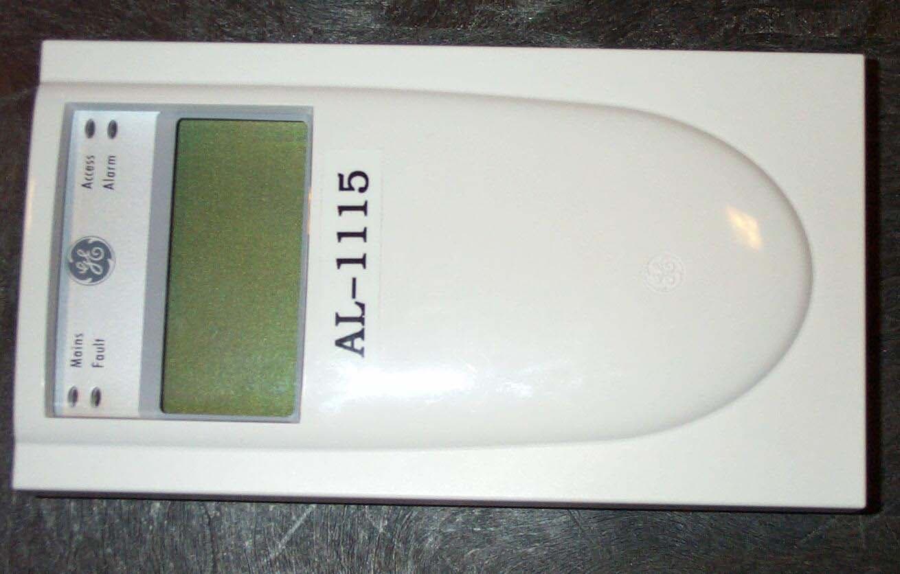
Click to zoom
Application Details
- Equipment Class
- DXX - Part 15 Low Power Communication Device Transmitter
- Date of Grant
- May 13, 2004
- Application Purpose
- Original Equipment
- Date of Application
- May 13, 2004
- Equipment Note
- Keypad with proximity reader transmitter
- Frequency Range
- 0.12500000 - 0.12500000
- Company
- UTC Fire & Security B.V.
- Country
- Netherlands
Documents & Files
Document Text
Text extracted from the exhibit documents filed with the FCC. Open a document above to read the original.
Users Manual
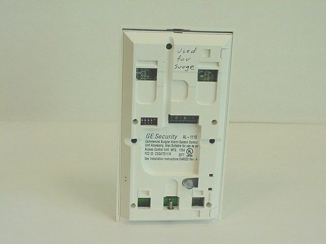
1 AL-111X Arming Station Product Summary AL-111X Arming Station Installation and Programming Instructions Models: AL-1110 - two-line LCDAL-1111 - four-line LCD AL-1115 - two-line LCD with Smart Card readerAL-1116 - four-line LCD with Smart Card reader Used with Alliance control panels, AL-111X Series RAS are used for controlling security system alarm and access functions. Product features include: •Beeper •Integrated tamper switch •Two- or four-line Liquid Crystal Display (LCD) •Multiple text formats for four-line LCD models (AL-1111 and AL-1116) •Embedded Smart Card Reader (AL-1115 and AL-1116) •Access and system status Light Emitting Diodes (LED) •The RAS may be used up to 5,000 feet (1.5 km) from the control panel or four-door controller DGP. •One open collector output is provided to drive a small relay, LED, etc. One input is provided for an egress function. •Plastic hinged cover Alliance g Figure 1. Status LEDs LCD Display Keypad Smart Card Reader (AL-1115 and AL-1116 only) behind keypad Area LEDs Cover Locking Screw DIP Switches COMMS Terminal Tamper Switch Cable Entry Cable Entry Mounting Plate Mounting Screw Holes Cable Entry Power Fault Access Alarm 2 AL-111X Arming Station Mounting the RAS 1.Attach the mounting plate to the mounting surface using the three screws provided. 2.Ensure that the back tamper switch (see Figure 1) can rest on a flat surface flush with the back of the mounting plate (avoid rough or non-flat surfaces). 3.If rear cable entry is used (through the mounting plate), cut a hole in the mounting surface for cable access. 4.Set the RAS address using DIP switches 1 through 4 (see DIP Switch Settings). 5.Set the COMMS (System BUS) termination switch using DIP switch 5, if required. 6.Terminate the COMMS (System BUS) cabling. Note All power should be turned off to the control panel before wiring the RAS. 7.Insert plastic cable entry blanking plugs (provided) into the back of the RAS to blank any unused cable entry channels (see Figure 1). 8.Place the RAS onto the mounting plate and lock in place by moving the unit down by about 0.3 inches (8mm). 9.Tighten the locking screw at the base of the RAS till firm. Do not over-tighten. Tamper Switch The back tamper switch (see Figure 1) must be sealed for the system to work correctly. Make sure that the tamper switch rests on a surface so that it remains depressed when the RAS is mounted. If the unit is tampered with the tamper switch should spring open. In operation, the LCD display will show “RAS Tamper” when not sealed. Removing the Cover and Mounting Plate The RAS cover is hinged at the bottom. To open, grasp the cover at the sides or the top and pull gently - the cover will swing down on its pins (see Figure 1). The cover may be fully removed by gently prizing one of the pins away from the body of the RAS and pulling. The metal mounting plate at the back is held by a locking screw (see Figure 1). To remove the mounting plate, loosen the screw by at least 8mm (0.315 in.), slide the mounting plate down, and then pull the bottom of the mounting plate away from the body of the RAS. DIP Switch Settings DIP switches are located on the back of the RAS (see Figure 1) and are used for setting the RAS address and the System BUS termination (TERM) condition. RAS Address Switches Use switches 1 to 4 to set the RAS address (as well as the reader address for AL-1115 and AL-1116). See Figure 3. TERM Switch Use switch 5 (see Figure 2) to set the TERM (System BUS termination) to “ON”, if needed. There must be no more than two TERM switches or links set to “ON” for any System BUS. Refer to the control panel installation guide for details about the use of TERM switches or links. Figure 3. RAS Address DIP Switch Settings Switch toggles are indicated as black. Example: RAS 1 = Off, Off, Off, Off All switches shown in the OFF position RAS Address TERM 1 2 3 4 5 ON ECE Figure 2. DIP Switches 3 AL-111X Arming Station Connections A terminal block on the back of the RAS (see Figure 1) is used for the COMMS (System BUS) connection. System BUS Connection (D+ and D-) The RAS is connected to the Alliance panel via the RS-485 System BUS, up to 5,000 feet (1.5 km) from the control panel or the four-door controller DGP. It is recommended to use a 2-pair twisted, shielded data cable (Beldon 8723). The shield of any System BUS cable must be connected to system ground at one end only. The AL-111X RAS is not provided with an Earth connection for this purpose. If the System BUS is “daisy-chained” to the RAS, ensure that the shield of the cable is jointed to provide continuity of data cable shield. •D+ is the data positive connection of the System BUS. •D- is the data negative connection of the System BUS. Power Supply (+12 and 0V) Powered by the control panel The RAS can be powered using the System BUS “+” and “-” power from the control panel, if the distance between the RAS and the control panel does not exceed 328 feet (100 m). Powered by separate power supply The RAS can be powered by AUX PWR from a DGP, or by an auxiliary power supply. When using an auxiliary power supply: •Connect the “+” of the local power supply to the “+12” terminal of the RAS. Do not connect the “+” power of the System BUS to the RAS. •Connect the “-” of the local power supply to the “0V” terminal of the RAS and to the “-” power of the System BUS. •For optimal performance, adjust the power supply to 13.8 VDC. Figure 4. Connections for Powering the RAS from a Separate Power Supply Egress Contol and Open Collector (IN and OUT) Terminals IN and OUT are optionally used for egress control and door relay operation: •IN - An egress botton (normally open, momentary push-button switch) can be connected across the “IN” and “0V” terminals (see Figure 5). When pressed, the button controls the request-to-exit function to the panel. •OUT - Open collector output must be assigned with a number according to type of control panel. Use the first output control assigned to the RAS. Refer to the contr…
Text truncated - open the document above for the full version.
Test Report
Underwriters Laboratories Inc. A not-for-profit organization dedicated 1655 Scott Blvd to public safety and committed to Santa Clara, CA 95050 quality service for over 100 years EMC Services Department Tel: (408) 876-2905 Fax: (408)556-6071 ELECTROMAGNETIC COMPATIBILITY (EMC) Report EMISSIONS GE Interlogix Model AL-111x Series Keypad FCC ID : CGS-ATS111X May 4, 2004 Project No.: 04CA09977 Test Report No.: NC-050404 Company: GE Interlogix Model #:AL-111x Series keypad Project: 04CA09977 Report #:NC4346-050404 Page 2 of 32 REPORT DIRECTORY Title Section General Information 1.0 Scope 1.1 Purpose 1.2 Test Results 1.3 Documentation Review/Approval 1.4 General Product Description 2.0 Justification of Configuration 2.1 EUT Operating Mode(s) 2.2 Environmental Conditions in Test Lab 3.0 Calibration Details of Equipment Used for Measurement 4.0 Test Facility 5.0 Accreditations and Authorizations 6.0 Emissions Test Regulations 7.0 Equipment Classifications 7.1 FCC Requirement Summary 7.2 Field Strength Calculations 7.3 Measurement Uncertainty 7.4 Measurement Bandwidths 7.5 Conducted Voltage Emissions 7.6 Radiated Electric Field Emissions 7.7 Radiated Electric Field Fundamental Emission Measurements 7.8 Company: GE Interlogix Model #:AL-111x Series keypad Project: 04CA09977 Report #:NC4346-050404 Page 3 of 32 1.0 General Information 1.1 Scope Underwriters Laboratories Inc., authorizes the above named company to reproduce this Report, provided it is reproduced in it’s entirety. The data in this Report reflects only the items tested in the configurations and mode of operations described. All data recorded and photographs represents testing under the worst case conditions permitted by the requirements applied to the product. It is the manufacturer’s responsibility to assure that additional production units are manufactured with identical electrical and mechanical components. Any modifications necessary for compliance made during testing must be implemented in all production units for compliance to be maintained. Underwriters Laboratories Inc., shall have no liability for any deductions, inferences or generalizations drawn from this report. This report shall not be used by the client to claim product certification, approval, or endorsement by NVLAP, NIST, or any agency of the United States government. 1.2 Purpose Testing was performed to the following regulations: Emissions Standards used: CFR 47 Part 15 Subpart B, CFR 47 Part 15 Subpart C Company: GE Interlogix Model #:AL-111x Series keypad Project: 04CA09977 Report #:NC4346-050404 Page 4 of 32 1.3 Test Results In Compliance Not in Compliance 1.4 Documentation Review/Approval Project Management: Technical Review By: Bill Barry Tim Lee Staff Engineer Staff Engineer International EMC Services International EMC Services Department 3014A Department 3014A Company: GE Interlogix Model #:AL-111x Series keypad Project: 04CA09977 Report #:NC4346-050404 Page 5 of 32 2.0 General Product Description Applicant : GE Interlogoix Manufactured By : Same as Applicant FCC ID : CGGATS111X Applicant Address : 12345 S Leveton Drive Tualatin, OR 97062 Applicant Contact : Tracey Boyle Model/Type No. : AL-111x Series Date of Issue : 4-15-2004 File No. : NC4346 Test Report No. : NC4346-041504 Project No. : 04CA09977 Product Description The equipment under test (EUT) is a keypad for use with the applicant’s alarm control units. A proximity RFID transmitter operating at 125 kHz is provided within the keypad’s enclosure. Equipment Size, Mobility, and Identification Dimensions: 6.5 by 3.5 by 0.825 in. Mobility: Hand-held Table-top Floor-standing Wall Mount Serial No: Not Provided Electrical Ratings Voltage [Volts] Current or Power Frequency [Hz] Phase Eut 9-14 V dc 165 mA DC N/A Test Voltage & Frequency Unless indicated otherwise on the individual data sheet or test results, the test voltage and frequency was as indicated below. Voltage Frequency 12 V DC Clocks/Oscillators 125 kHz Equipment Type Prototype Pre-Production Production Company: GE Interlogix Model #:AL-111x Series keypad Project: 04CA09977 Report #:NC4346-050404 Page 6 of 32 Model Differences The series AL-111x covers 4 different models. Models AL-1110 and AL-1111 are not provided with proximity card readers. Model AL-1115 and AL-1116 contain the card reader. Model AL-1115 was tested to represent all models. Any other model(s) represented by the models tested in this investigation will be documented by the manufacturer. Device Modifications The following modifications were necessary for compliance: None EUT and Peripherals Description Manufacturer Model/Part # Serial Number Keypad (EUT) GE Interlogix AL-1115 None Provided Alarm Panel GE Interlogix AL-4017 None Provided Cables Cable Type Shield Length (meters) Ferrite Connector Connection Point 1 Connection Point 2 Jacketed Solid Yes 20 N Hardwire Keypad Alarm Panel 2.1 Justification of Configuration The unit is provided in one configuration. 2.2 EUT Operating Mode(s) Equipment under test was operated during the measurement under the following conditions: The system was tested in the stand-by mode. A RFID card was placed near the field of transmitter during the test. 3.0 Environmental Conditions in Test Lab Temperature: 20-25 °C Atmospheric Pressure: 680-1060 mbar Relative Humidity: 30-60% 20.1-31.3 in. Hga 4.0 Calibration Details of Equipment Used for Measurement Test equipment and test accessories are calibrated on regular basis. The maximum time between calibrations is one year or what is recommended by the manufacturer, whichever is less. All test equipment calibrations are traceable to the National Institute of Standards and Technology (NIST), therefore, all test data recorded in this report is traceable to NIST. Company: GE Interlogix Model #:AL-111x Series keypad Project: 04CA09977 Report #:NC4346-050404 Page 7 of 32 5.0 Test Facility Underwriters Laboratories Inc. 1655 Scott Blvd. Santa Clara, CA 95050 Phone: (408) 876-2905 Fax: (408) 556-6071 Company: GE Interlo…
Text truncated - open the document above for the full version.
Test Setup Photos
Radiated Emissions: General Arrangement Radiated Electric Field Emissoins 30 MHz- 1 GHz Antenna Location Radiated Electric Field Emissions (up to 30 MHz) Conducted Voltage Emissions:
Contact Information
Applicant
Roger Palmen(Lead Product Engineer)
Technical Contact
GE SecurityTracy Boyle
[email protected]800-547-2556
12345 SW Leveton Dr. · Tualatin, Oregon · United States
Non-Technical Contact
GE SecuritySteven Wilson
[email protected]800-547-2556
Test Firm
Underwriters Laboratories Inc.Bob Miller
Technical Specifications
| # | Rule Parts | Frequency Range | Power Output |
|---|---|---|---|
| 1 | 15C | 0.125 MHz - 0.125 MHz | - |
Other Applications from UTC Fire & Security B.V.
CGGAA3
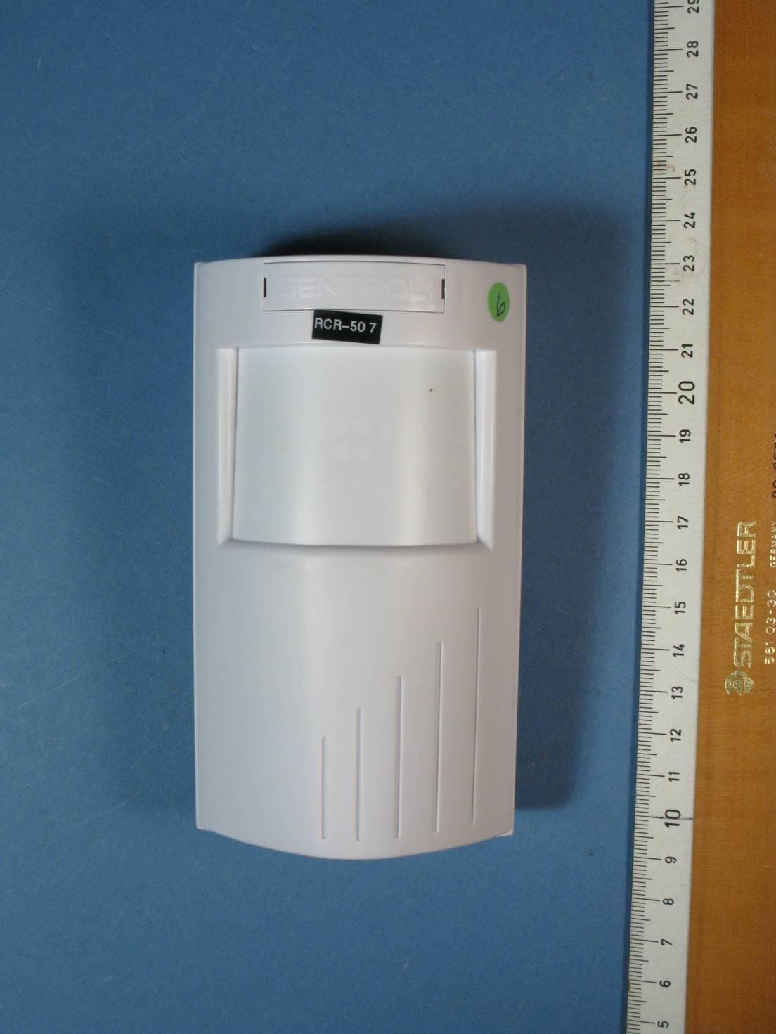
Jun 20, 2011RCR-50, RCR-PET, RCR-C
Equipment Class
DXX - Part 15 Low Power Communication Device Transmitter
CGG-AL-1623
Jan 07, 2003Smart Card Programmer
Equipment Class
DCD - Part 15 Low Power Transmitter Below 1705 kHz
CGGNX1700E
Oct 24, 2002Remote Control Security Device
Equipment Class
DCD - Part 15 Low Power Transmitter Below 1705 kHz
CGGATS1190-1192
Oct 23, 2002Access Control Card Reader
Equipment Class
DCD - Part 15 Low Power Transmitter Below 1705 kHz
CGGAA2
Sep 14, 2000Field Disturbance Sensor for Security Systems
Equipment Class
DXX - Part 15 Low Power Communication Device Transmitter