CHXFS60TXOLED remote
Rockford Corporation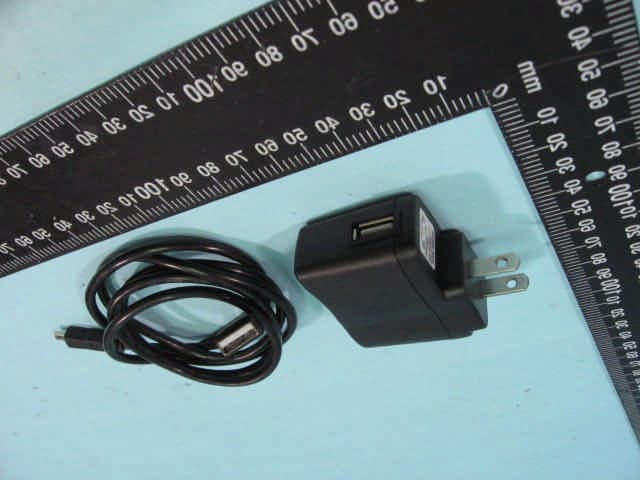
Click to zoom
Application Details
- Equipment Class
- DSR - Part 15 Remote Control/Security Device Transceiver
- Date of Grant
- Nov 07, 2010
- Application Purpose
- Original Equipment
- Date of Application
- Nov 07, 2010
- Equipment Note
- OLED remote
- Frequency Range
- 433.92000000 - 433.92000000
- Company
- Rockford Corporation
- Country
- United States
Documents & Files
Document Text
Text extracted from the exhibit documents filed with the FCC. Open a document above to read the original.
Users Manual
1 FS-60 2-Way OLED Remote Paging Alarm & Engine Starting System OPERATION INSTRUCTIONS INTRODUCTION CONGRATULATIONS on your choice of the OLED Remote Paging Alarm & Remote Engine Starting System with 3 D Graphics by Crimestopper Security Products Inc. CONTACT INFORMATION: TECHNICAL SUPPORT (800)-998-6880 Monday - Friday 8:00am - 4:30pm Pacific Website: www.crimestopper.com E-mail: [email protected] CRIMESTOPPER SECURITY PRODUCTS INC. 1770 S. TAPO STREET SIMI VALLEY, CA. 93063 REV. A 7.2009 This device complies with FCC Rules part 15. Operation is subject to the following two conditions: 1) This device may not cause interference, and (2) this device must accept any interference that may be received, including interference that may cause undesired operation. The manufacturer is not responsible for any radio or TV interference caused by unauthorized modification to this equipment. Such modification could void the user's authority to operate the equipment. 2 Lift side cover ► for USB PLUG Charging Battery THE REMOTE CONTROLS 1-WAY - SIDEKICK REMOTE: The 1-Way sidekick remote adds flexibility to your system. You can have the convenience of operating your system without needing to carry the larger pager remote. The Sidekick remote has less range and offers all of the same operation features except for page-back confirmation. The 1-Way Sidekick Remote uses two CR-2025 Lithium 3 Volt Batteries. 2-WAY - TOUCH SCREEN PAGER / REMOTE CONTROL: The 2-Way OLED pager remote control is used to send and receive information to and from the vehicle. The vehicle will confirm remote commands by transmitting High Frequency FM signals to your pager over long distances. Your range will vary depending on location, terrain, and local RF noise/interference. This system is not guaranteed to page you if you are behind concrete walls, underground, in a large structure, or in an area with high levels of electronic interference. Handle the pager/remote with care. The LCD display and/or the electronics may be damaged if subjected to abuse. The OLED remote control will confirm everything on the display along with voice and vibration. The voice and vibration can be turned ON or OFF thru the menu choices. • Press Side Scroll-Wheel to display ALARM Status and exit Menu Options ARM / LOCK DISARM / UNLOCK START TRUNK ▲ ◄Scroll - Wheel ▼ 3 • Scroll Scroll-Wheel “UP” to display the Following screens • Scroll Scroll-Wheel “DOWN” to display the Following screens Power OFF Button: Scroll-Wheel Down This turns the Power Off. The Remote will not receive signals from vehicle until button # 4 is pressed about 4 seconds. The screen will change colors, and then show Start-Up Screen. Arming / Locking: Press the Lock Button on the remote control. The System will arm and confirm with one siren and horn chirp, one park lights flash, and the LED will begin to flash slowly. Power locks will lock (if equipped). The starter disable circuit will turn on. The 2-Way LCD Pager will give voice confirmation “System Armed” while displaying a Locking symbol. After a short delay, the system will be completely armed. NOTE: The siren and horn chirps are programmable ON or OFF (option # 4). Open Door Alert / Bypass: Upon arming, the system will warn you if a door, hood or trunk is left open. The system will chirp and flash the parking lights 4 times to warn you of a problem. The system will wait up to 45 seconds (programmable 0, 15, 30, 45 seconds) for the dome light to turn off. The open zone will automatically be bypassed until closed. The alarm will continue to protect all other zones. Car Finder Mode: When the alarm system is armed, press the Lock Button. The siren, horn and lights will flash 6 times. This is useful in a large parking lot to help find your car. 4 Disarming / Unlocking: Press the Unlock Button on the remote control. The System will disarm and confirm with two chirps, two light flashes, and the LED will turn off. Power locks will unlock and Interior Dome light will turn on (if installed with these optional features). The 2-Way LCD Pager will confirm with “System Disarmed” while displaying an Unlock symbol. Driver’s Door Priority Unlock: Optional connection required This option separates unlock of the driver’s door from the passenger doors with the remote control. There are 2 choices of operation. • Default = Press and hold the Unlock Button for 2 seconds to unlock all doors. • Press the Unlock Button 2 times to unlock all doors. This is Remote Channel 2 output (Option # 10). This output can also be programmed for other auxiliary functions, consult your installer. Silent Arming: Scroll-Wheel Down To Arm without chirps, press the Silent Arm button # 1. The 2-Way LCD Pager will confirm with “System Armed”. Silent Disarming: Scroll-Wheel Down To Disarm without chirps, press the Silent Disarm button # 2. The 2-Way LCD Pager will confirm with “System Disarmed”. Arm without Shock Sensor Zone: Scroll-Wheel Down To arm the system without the shock sensor zone, press button # 3. The 2-Way LCD Pager will confirm with “System Armed”. Panic Mode: Ignition Key OFF Scroll-Wheel Down To sound the alarm in an emergency situation or to draw attention to your vehicle, press Button # 4 until the siren / horn sounds. The alarm will sound for 30 seconds. Press the Lock or Unlock Button to reset panic mode. Note: On 1-Way Sidekick remote, press the Buttons at the same time. Plus 5 Manual Arming Mode: The alarm system can be Manually Armed and Disarmed without the remote control. The door entry will change to a 20 second delay to allow disarm without sounding alarm. This is useful if you don’t have a remote control or go swimming. To Activate Manual Mode: 1. Turn Ignition Key off. 2. Press Valet Override Button 3 times and exit vehicle. 3. The system will arm 10 seconds after closing the door. 4. Disarm by Ignition On and press Valet Override button 4 seconds. Valet Mode: Solid Blue LED Valet Mode is disables the Alarm and Remote Engine Starting for…
Text truncated - open the document above for the full version.
External Photos
ETC Report No.:10-06-RBF-142 Sheet 1 of 8 Sheets FCC ID.: CHXFS60TX Rev. No 1.0 CONSTRUCTED PHOTOS of EUT A. EUT 1. Front View of EUT 2. Side View of EUT ETC Report No.:10-06-RBF-142 Sheet 2 of 8 Sheets FCC ID.: CHXFS60TX Rev. No 1.0 CONSTRUCTED PHOTOS of EUT 3. Top View of EUT 4. Side View of EUT ETC Report No.:10-06-RBF-142 Sheet 3 of 8 Sheets FCC ID.: CHXFS60TX Rev. No 1.0 CONSTRUCTED PHOTOS of EUT 5. Bottom View of EUT 6. Rear View of EUT ETC Report No.:10-06-RBF-142 Sheet 7 of 8 Sheets FCC ID.: CHXFS60TX Rev. No 1.0 CONSTRUCTED PHOTOS of EUT A. Adaptor 1. Front View of EUT 2. Side View of EUT ETC Report No.:10-06-RBF-142 Sheet 8 of 8 Sheets FCC ID.: CHXFS60TX Rev. No 1.0 CONSTRUCTED PHOTOS of EUT 3. Top View of EUT 4. Label View of Adaptor
Internal Photos
ETC Report No.:10-06-RBF-142 Sheet 4 of 8 Sheets FCC ID.: CHXFS60TX Rev. No 1.0 CONSTRUCTED PHOTOS of EUT 7. Internal View of EUT 8. Internal View of EUT ETC Report No.:10-06-RBF-142 Sheet 5 of 8 Sheets FCC ID.: CHXFS60TX Rev. No 1.0 CONSTRUCTED PHOTOS of EUT 9. Component View of PCB 10. Solder View of PCB ETC Report No.:10-06-RBF-142 Sheet 6 of 8 Sheets FCC ID.: CHXFS60TX Rev. No 1.0 CONSTRUCTED PHOTOS of EUT 11. Component View of PCB 12. Solder View of PCB
Test Report
Rev. No 1.0 FCC Part 15 EMI TEST REPORT of E.U.T. : OLED Remote FCC ID : CHXFS60TX MODEL : FS-60 Working Frequency : 433.920MHz for APPLICANT : Crimestopper Security Products, INC ADDRESS : 1770 South Tapo St, Simi Valley, California 93063 USA Test Performed by ELECTRONICS TESTING CENTER, TAIWAN NO.34, LIN 5, DINGFU TSUEN, LINKOU SHIANG TAIPEI COUNTY, TAIWAN, 24442, R.O.C. TEL : (02)26023052 Fax : (02)26010910 http://www.etc.org.tw ; e-mail: [email protected] Report Number : 10-06-RBF-142 ETC Report No.:10-06-RBF-142 FCC ID.: CHXFS60TX Rev. No 1.0 TEST REPORT CERTIFICATION Applicant : Crimestopper Security Products, INC 1770 South Tapo St, Simi Valley, California 93063 USA Manufacturer : Tesor Plus Corp. 6 th Floor, No.11, Alley 11, Lane 327, Section 2, Chung-Shan Road, Chung-Ho City, Taipei Hsien, Taiwan Description of EUT : a) Type of EUT : OLED Remote b) Trade Name : Fortress c) Model No. : FS-60 d) FCC ID : CHXFS60TX e) Working Frequency : 433.920 MHz f) Power Supply : Tx: DC 3.7 V Battery Regulation Applied : FCC Rules and Regulations Part 15 Subpart C (2009) I HEREBY CERTIFY THAT: The data shown in this report were made in accordance with the procedures given in ANSI C63.4 and the energy emitted by the device was founded to be within the limits applicable. I assume full responsibility for accuracy and completeness of these data. Note : 1. The results of the testing report relate only to the items tested. 2. The testing report shall not be reproduced except in full, without the written approval of ETC. ETC Report No.:10-06-RBF-142 FCC ID.: CHXFS60TX Rev. No 1.0 Issued Date : Aug. 30, 2010 Test Engineer : (Vincent Chang, Engineer ) Check By : ( Charles Wang, Supervisor ) Approve & Authorized Signer : Will Yauo, Manager EMC Dept. II of ELECTRONICS TESTING CENTER, TAIWAN ETC Report No.:10-06-RBF-142 FCC ID.: CHXFS60TX Rev. No 1.0 Table of Contents Page 1. GENERAL INFORMATION.....................................................................................................................................................1 1.1 PRODUCT DESCRIPTION...........................................................................................................................................................1 1.2 CHARACTERISTICS OF DEVICE:...............................................................................................................................................1 1.3 TEST METHODOLOGY..............................................................................................................................................................1 1.4 TEST FACILITY..........................................................................................................................................................................1 2. DEFINITION AND LIMITS.......................................................................................................................................................2 2.1 DEFINITION................................................................................................................................................................................2 2.2 RESTRICTED BANDS OF OPERATION.....................................................................................................................................2 2.3 LIMITATION...............................................................................................................................................................................2 2.4 LABELING REQUIREMENT.......................................................................................................................................................4 2.5 USER INFORMATION.................................................................................................................................................................4 3 SYSTEM TEST CONFIGURATION.........................................................................................................................................5 3.1 JUSTIFICATION..........................................................................................................................................................................5 3.2 DEVICES FOR TESTED SYSTEM...............................................................................................................................................5 4. RADIATED EMISSION MEASUREMENT.............................................................................................................................6 4.1 APPLICABLE STANDARD.........................................................................................................................................................6 4.2 MEASUREMENT PROCEDURE..................................................................................................................................................6 4.3 TEST DATA.................................................................................................................................................................................8 4.4 FIELD STRENGTH CALCULATION........................................................................................................................................12 4.5 ACTIVATE TIME......................................................................................................................................................................12 4.6 CALCULATION OF DUTY FACTOR.......................................................................................................................................12 4.7 RADIATED TEST EQUIPMENT...............................................................................................................................................15 4.8 MEASURING INSTRUMENT SETUP.......................................................................................................................................15 4.9 RADIATED MEASUREMENT PHOTOS.....…
Text truncated - open the document above for the full version.
Test Setup Photos
ETC Report No.:10-06-RBF-142 Sheet 16 of 25 Sheets FCC ID.: CHXFS60TX Rev. No 1.0 4.9 Radiated Measurement Photos ETC Report No.:10-06-RBF-142 Sheet 17 of 25 Sheets FCC ID.: CHXFS60TX Rev. No 1.0 ETC Report No.:10-06-RBF-142 Sheet 24 of 25 Sheets FCC ID.: CHXFS60TX Rev. No 1.0 5.6 Photos of Conduction Measuring Setup
Contact Information
Applicant
Jonathan Comune(Director of Business Planning)
Test Firm
Taiwan Testing and Certification CenterAnderson Ku
Technical Specifications
| # | Rule Parts | Frequency Range | Power Output |
|---|---|---|---|
| 1 | 15.231 | 433.92 MHz - 433.92 MHz | - |
Other Applications from Rockford Corporation

CHXRX01-2W433
Sep 02, 2014Car Alarm - RS2-G3
Equipment Class
DSC - Part 15 Security/Remote Control Transmitter
CHXT34A-1W433
Aug 27, 2014Car alarm -RS2-G3
Equipment Class
DSC - Part 15 Security/Remote Control Transmitter
CHXT34A-2W433
Aug 26, 2014Car alarm -RS2-G3
Equipment Class
DSC - Part 15 Security/Remote Control Transmitter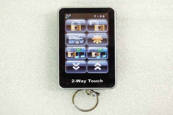
CHXFS99TX915
Oct 31, 2012Touch Remote
Equipment Class
DXX - Part 15 Low Power Communication Device Transmitter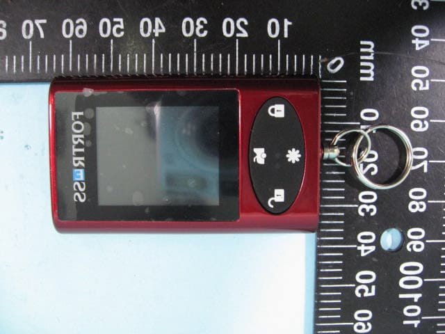
CHXFS90TX915
Nov 07, 2010mini touch remote
Equipment Class
DXT - Part 15 Low Power Transceiver, Rx Verified