CHXSP101Remote control
Rockford Corporation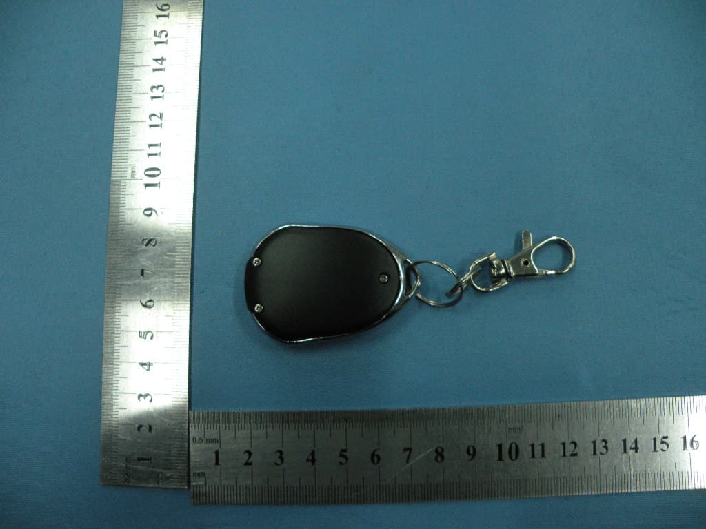
Click to zoom
Application Details
- Equipment Class
- DSC - Part 15 Security/Remote Control Transmitter
- Date of Grant
- Apr 01, 2010
- Application Purpose
- Original Equipment
- Date of Application
- Apr 01, 2010
- Equipment Note
- Remote control
- Frequency Range
- 433.92000000 - 433.92000000
- Company
- Rockford Corporation
- Country
- United States
Documents & Files
Document Text
Text extracted from the exhibit documents filed with the FCC. Open a document above to read the original.
Users Manual
1 SP-101 REMOTE CONTROL ALARM SYSTEM INSTALLATION & OPERATING INSTRUCTIONS INTRODUCTION CONGRATULATIONS on your choice of a “Security Plus” Remote Alarm System by Crimestopper Security Products Inc. This booklet contains the information necessary for installing, using, and maintaining your alarm system. If any questions arise, contact your installation dealer or Crimestopper Security Products Inc. at the Tech Support number below. This installation book is designed for the installer or individual with an existing understanding of automotive electrical systems, along with the ability to test and connect wires for proper operation. To ease installation, we suggest that you READ THIS MANUAL before beginning your installation. This book is provided as a GENERAL GUIDLINE and the information contained herein may differ from your vehicle. TECH SUPPORT Mon-Fri 8:00 AM-4:30 PM Pacific Time www.crimestopper.com Phone (800) 998-6880 FAX (805) 581-9500 REV. A 03.2010 This device complies with FCC Rules part 15. Operation is subject to the following two conditions: 1) This device may not cause interference, and (2) this device must accept any interference that may be received, including interference that may cause undesired operation. The manufacturer is not responsible for any radio or TV interference caused by unauthorized modification to this equipment. Such modification could void the user's authority to operate the equipment. 2 TABLE OF CONTENTS Installation Cautions & Warnings.................................................................................................2 Control Module & Component Mounting........................................................................................3 Wiring....................................................................................................................................4-5 Power Door Lock Wiring.............................................................................................................6 Transmitter Programming..........................................................................................................7 Option Programming.............................................................................................................8-10 Operating Instructions..........................................................................................................11-13 Car Jack Protection..................................................................................................................14 LED / Valet Switch....................................................................................................................15 Shock Sensor...........................................................................................................................15 System Wiring Diagram............................................................................................................16 INSTALLATION CAUTIONS & WARNINGS BEFORE BEGINNING, check all vehicle manufacturer cautions and warnings regarding electrical service (AIR BAGS, ABS BRAKES, ENGINE COMPUTERS, BATTERY etc.). WE RECOMMEND the use of a VOLT/OHM METER to test and verify wiring circuits. Test lights or illuminated probes can cause damage to on-board computer or engine management systems. DO NOT exceed maximum output ratings or damage may occur. Electrical current limits for this alarm are listed where applicable on the system diagram (Pg. 16). If you are unsure about the current load, of a specific circuit on your vehicle, measure the load first with an amp-meter before connecting. WE RECOMMEND that the MAIN SYSTEM FUSE be REMOVED before jump starting, using a battery charger, or changing the battery. A voltage surge or high boost condition could damage alarm circuits. DO NOT ROUTE ANY WIRING THAT MAY BECOME ENTANGLED with brake, and gas pedals, steering column, or any other moving parts in the vehicle. 3 CONTROL MODULE MOUNTING DO NOT Mount the control unit in the engine compartment! DO NOT Mount the control unit or wiring harness where they can become entangled with moving parts such as brake/gas/clutch pedals, or the steering column! The alarm control module should be mounted in a concealed location. The Placement of the module will affect the distance from which the remote transmitter can control the unit. The antenna wire should be routed away from any metal if possible. Do not alter the length of the antenna wire or route it with other wires. Do not ground the antenna wire. Fasten the module to a bracket or wire harness using the cable ties provided. Underdash Mounting: If you are locating the control unit underdash, mount it as high as possible, not easily located by an intruder. Driver’s Side Underdash mounting provides an easy location for wiring most of the system’s connections, however this is a common location for an intruder to check for an alarm after breaking into the vehicle. The left side of the vehicle may contain more metal and or wiring that will create interference and decrease the operating range of the system. Passenger Side underdash is a good location, however some extra wiring may be needed to extend wires across from the driver’s side. Under-seat / Center Console mounting is also a possibility, but NOT RECOMMENDED. The system’s transmitter range will be reduced by the metal structures of the seat or center console and the unit may also be exposed to moisture from spilled drinks etc. Moisture or water damage is not covered under the warranty and will be subject to repair charges. Under seat or console mounting will create more difficulty if you need to access the unit for service or want to add-on features or connections later. Use this location as a last resort. COMPONENT MOUNTING SIREN: Mount the siren under the hood to an inner fender-well or other body surface with the open end facing downward. SHOCK SENSOR: Mount the included shock sensor with wire ties to an under dash wire harness or fasten with screws…
Text truncated - open the document above for the full version.
Block Diagram
SP100 (TA25) ELECTRIC CI RCUIT STRUCTURE DRAWING
Cover Letter(s)
Crimestopper Security Products, Inc. ____________________________________________________ SCS-F18: Project and Product Certification Representative Authorization Letter Page 1 of 2 Rev 2.0 2206 Ringwood Avenue San Jose, CA 95131 Tel: 408-526-1188 Fax: 408-526-1088 Email: [email protected] Project and Product Certification Representative Authorization Letter Revision History Reason for Amendment (current / obsolete) From To Approved Date Initial Release (current) 1.0 1.0 Nov-14-2006 Revised wording (current) 1.0 2.0 Sept–25-2007 Crimestopper Security Products, Inc. ____________________________________________________ SCS-F18: Project and Product Certification Representative Authorization Letter Page 2 of 2 Rev 2.0 (March 27, 2010) To: SIEMIC, INC. 2206 Ringwood Avenue, San Jose, CA 95131 USA Dear Sir/Madam, Re: Project and Product Certification Representative Authorization Letter We, Crimestopper Security Products, Inc. hereby authorize SIEMIC, INC. to act as a Certification Body for certifying for the following project(s): (Product description, model name) FCC ID: CHXSP101 Product name: Remote control Model: SP101 We affirm that between SIEMIC and Crimestopper Security Products, Inc., any difference in understanding, including test plan, measurement methods, applicable standards and relevant procedures and processes have been resolved prior to commencement of testing activities. Sincerely, Signature Mr. Howard Miller / President Title: President Telephone: 805-526-9400-217 Email: [email protected] Date: March 27, 2010
External Photos
To p Vi e w Bottom View Front View Left View Rear View Right View
ID Label/Location Info
FCC ID: CHXSP101 This device complies with Part 15 of the FCC Rules. Operation is subject to the following two conditions: (1) this device may not cause harmful interference, and (2) this device must accept any interference received, including interference that may cause undesired operation.
ID Label/Location Info
Label Location
Internal Photos
Label Location
Operational Description
The Operating Guider of SP100(TA25) Remote Control DESCRIPTION: This device is to transmit code, When click one button, a group of codes are modulated to be 433.92MHz frequency ASK radio, then send out by built-in PCB antenna. IC WORKING MANNER OF REMOTE CONTROL FIG1 Encode IC eV1527 FIG2 Remote Control As shown in FIG: Keys (K0, K1, K2, K3) link corresponding buttons of remote control (FIG2), when press one button, the button swtiches DC power on, then encode IC outputs a group of built-in fixed codes (same 20-digit address codes and different data 4-digit codes) via RF transmitting circuit to emanate. When release the button, DC power swtich off, RF transmitting circuit stops sending. The use method of remote control’s all buttons is same. --1/2-- Electrical Characteristic: DC Supply Voltage (V DD) 12 volt Maximum Transmitting Power ≦10mW Operating Current: ≦10mA Standby Current 0mA Operating Frequency 433.92MHz Operating Coditions: Storage Temperature Range -40°C(-104°F) ~ +100°C(-212°F) Operating Temperature Range: -20°C(-68°F) ~ +85°C(+185°F) Operating Humidity Range 25% ~95% SP100 Button’s Definitions First button: Define: LOCK, press once, arm the system; car finding Second button Define: UNLOCK, press once, unlock and disarm Third button: Arm the system without chirp (mute mode). Forth button: Trunk Release. Press once, release the trunk. --2/2--
Schematics
TA25(433.92Mhz) CZB20100306 YZ 2010.3.9 2010.3.9 2010.3.9 2010.3.8 YC YCA HZW B 11 REV:SIZE:CODE: DRAWN:DATED: DATED:CHECKED: QUALITY CONTROL:DATED: DATED:RELEASED: COMPANY: TITLE: DRAWING NO: SHEET: OFSCALE: REVISION RECORD APPROVED:ECO NO: A B D DATE: 123456 D C A B C LTR 1 2 3 4 8 7 6 5 U1 EV1527 R5 47K R2 5.6K Q1 2TY SW1 SW2 SW3 SW4 R3 1K R4 200K R1 10K D1 LED C5 102P C4 102P Q2 R25 R6 33K L1 1uH Y1 433.92M R7 100R C10 2pF C6 10pF C9 4pF C1 3pF C3 3pF C8 102P B1 12V C2 104P C7 NC PDF 文件使用 "pdfFactory" 试用版本创建 www.fineprint.cn
Test Report
Shenzhen Certification Technologh Service Co., Ltd 3F, Bldg27,Area A, Tanglang Industrial Zone, Xili Town, Nanshan District, ShenZhen, Guang dong, P.R. China. FCCID: CHX-SP101 Page 1 of 27 TEST REPORT FCC ID: CHXSP101 Applicant : Crimestopper Security Products, Inc. Address : 1770 S. Tapo Street, Simi Valley, CA 93063 Equipment under Test (EUT): Name : Remote Control Model : SP101 Standards : FCC PART 15, SUBPART C : 2008 (Section 15.231) Report No. : STE100322179 Date of Test : March 22-25, 2010 Date of Issue : March 26, 2010 Test Result : PASS * * In the configuration tested, the EUT complied with the standards specified above Authorized Signature (Mark Zhu) General Manager The manufacture should ensure that all the products in series production are in conformity with the product sample detailed in this report. If the product in this report is used in any configuration other than that detailed in the report, the manufacturer must ensure the new system complies with all relevant standards. Any mention of Shenzhen Certification Technology Service Co., Ltd. Or test done by Shenzhen Certification Technology Service Co., Ltd. Approvals in connection with, distribution or use of the product described in this report must be approved by Shenzhen Certification Technology Service Co., Ltd. Approvals in writing. Report No.:STE100322179 FCCID: CHX-SP101 Page 2 of 27 TABLE OF CONTENT Description Page 1 General Information------------------------------------------------------------------------------------- 3 1.1 Description of Device (EUT)---------------------------------------------------------------------3 1.2 Description of Test Facility -----------------------------------------------------------------------4 2 EMC Equipment List --------------------------------------------------------------------------------- 4 3 Test Procedure ------------------------------------------------------------------------------------------- 5 4 Summary of Measurement ------------------------------------------------------------------------- 6 Occupied bandwidth -------------------------------------------------------------------------------------- 6 5 Radiation Emission----------------------------------------------------------------------------------- 7 5.1 Duty cycle------------------------------------------------------------------------------------------7 5.2 Radiation Emission Limits(15.209&231)------------------------------------------------- 10 5.3 Test Setup--------------------------------------------------------------------------------------- 10 5.4 Test Procedure--------------------------------------------------------------------------------- 12 5.5 Test Equipment Setting For emission test.est Result--------------------------------- 13 5.6 Test Condition---------------------------------------------------------------------------------- 13 5.7 Test Result-------------------------------------------------------------------------------------- 13 6 Occupied bandwidth -------------------------------------------------------------------------------- 17 6.1 Test limit------------------------------------------------------------------------------------------ 17 6.2 Method of measurement--------------------------------------------------------------------- 17 6.3 Test Setup--------------------------------------------------------------------------------------- 17 6.4 Test Results------------------------------------------------------------------------------------- 17 7 Transmission time ----------------------------------------------------------------------------------- 19 7.1 Test limit------------------------------------------------------------------------------------------ 19 7.2 Method of measurement--------------------------------------------------------------------- 19 7.3 Test Setup--------------------------------------------------------------------------------------- 19 7.4 Test Results------------------------------------------------------------------------------------- 19 8 Band Edge Check------------------------------------------------------------------------------------ 21 8.1 Test limit------------------------------------------------------------------------------------------ 21 Please refer section15.231 and section 15.205.----------------------------------------------- 21 8.2 Test Procedure--------------------------------------------------------------------------------- 21 8.3 Test Setup--------------------------------------------------------------------------------------- 21 8.4 Test Result-------------------------------------------------------------------------------------- 21 9 Antenna Requirement ------------------------------------------------------------------------------ 22 9.1 Standard Requirement----------------------------------------------------------------------- 22 9.2 Antenna Connected Construction---------------------------------------------------------- 22 9.3 Result--------------------------------------------------------------------------------------------- 22 10 Photographs of Test Setup ----------------------------------------------------------------------- 23 11 Photographs of EUT--------------------------------------------------------------------------------- 24 Report No.:STE100322179 FCCID: CHX-SP101 Page 3 of 27 1 General Information 1.1 Description of Device (EUT) Trade Name : N/A EUT : Remote Control Model No. : SP101 Type of Antenna : Integral Antenna Operation Frequency : 433.92 MHZ Channel number : 1 Modulation type : ASK Power Supply : DC 12V Supply by battery for Transmitter Rated PF output Power 71.60 dBuV (PK detector) Applicant : C rimestopper Security Products, Inc. Address : 1770 S. Tapo Street, Simi Valley, CA 93063 Manufacturer : ShenZhen Carsky Electronic Technology Co., Ltd Address : Block C12, Fuyuan Industrial City, Xixiang Baoan District Shenzhen China Report No.:STE100322179 FCCID: CHX-SP101 Page 4 of 27 1.2 Description of Test Facility Shenzhen Certification Technology Se…
Text truncated - open the document above for the full version.
Contact Information
Applicant
Jonathan Comune(Director of Business Planning)
Test Firm
Shenzhen Certification Technology Service Co.,LtdMark Zhu
Technical Specifications
| # | Rule Parts | Frequency Range | Power Output |
|---|---|---|---|
| 1 | 15.231 | 433.92 MHz - 433.92 MHz | - |
Other Applications from Rockford Corporation

CHXRX01-2W433
Sep 02, 2014Car Alarm - RS2-G3
Equipment Class
DSC - Part 15 Security/Remote Control Transmitter
CHXT34A-1W433
Aug 27, 2014Car alarm -RS2-G3
Equipment Class
DSC - Part 15 Security/Remote Control Transmitter
CHXT34A-2W433
Aug 26, 2014Car alarm -RS2-G3
Equipment Class
DSC - Part 15 Security/Remote Control Transmitter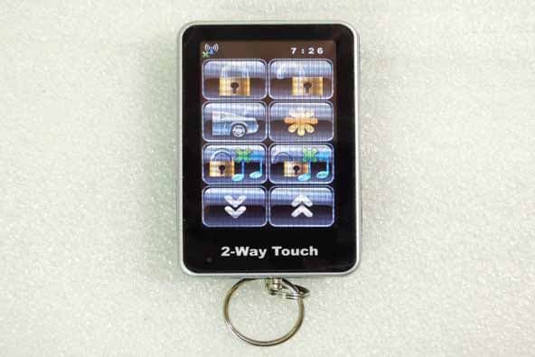
CHXFS99TX915
Oct 31, 2012Touch Remote
Equipment Class
DXX - Part 15 Low Power Communication Device Transmitter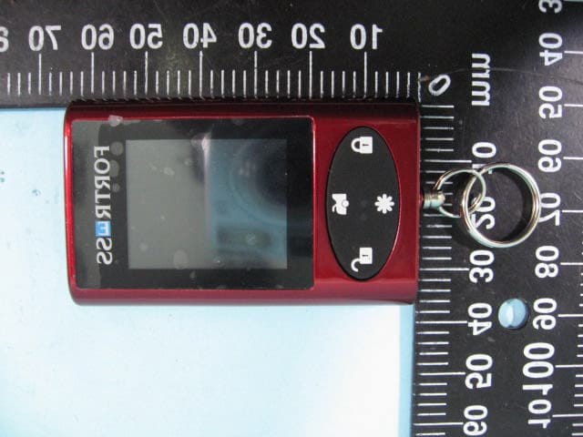
CHXFS90TX915
Nov 07, 2010mini touch remote
Equipment Class
DXT - Part 15 Low Power Transceiver, Rx Verified