CICCAE-A30-7'X' Band Radar
Kelvin Hughes Limited
Click to zoom
Application Details
- Equipment Class
- MRD - Marine Radar
- Date of Grant
- Mar 28, 2002
- Application Purpose
- Original Equipment
- Date of Application
- Jan 31, 2002
- Equipment Note
- 'X' Band Radar
- Frequency Range
- 9380.00000000 - 9440.00000000
- Company
- Kelvin Hughes Limited
- Country
- United Kingdom
Documents & Files
Document Text
Text extracted from the exhibit documents filed with the FCC. Open a document above to read the original.
Users Manual
CHAPTER 2 INSTALLATION GENERAL 1The Antenna/Transceiver is to be mounted on a rigid platform which provides clearance from other structures for the rotating antenna. The height and position of the platform is to be such that the radiated beam is unobstructed forward (i.e. beam-to-beam through the ship’s head) and the vertical radiated beam clearing the ship’s bow. 2There are two versions of the MkV Transceiver covered in this publication: (1)Low Speed Turning Mechanism CAE-A30/7. (2)High Speed Turning Mechanism CAE-A30/8. 3The High Speed Turning Mechanism uses an external downmast Power Supply CZZ-A22 to provide +40V to drive the turning motor. The Low Speed Turning Mechanism uses +27V power supplies from the display to drive the turning motor. SAFETY NOTES 4Electrical power supplies are to be isolated to any part of the platform when mounting an antenna/transceiver. A suitable safety platform or harness should be used to avoid personal injury when working aloft. (1)A working platform is to be provided for installing or servicing the assembly. This should be positioned approximately a metre below the base of the Transceiver housing with a guard rail surrounding it. (2)A flat steel plate (12mm thick approx.), pre-drilled (in accordance with Figure 1) to accommodate the Transceiver unit and the cable from the Display. The steel plate must be mounted horizontally and braced with struts for rigidity. (3)The plate has to be sited in a clear area where the turning Antenna cannot be obstructed by any cables, mast halyards etc. (4)The Antenna and Transceiver Unit must be hoisted to the fixing position using a secured block and tackle or rope strops. (5)Safety personnel must ensure that persons do not encroach on the area of work. (6)The Antenna and Transceiver Unit mustNOTbe lifted by the array, but the complete unit secured and hoisted evenly. KH1207 Chapter 2 mkv3Issue 2 EQUIPMENT LOCATION Transceiver and Turning Mechanism 5The Transceiver/Turning Mechanism should be installed in such a position where Blind Arcs, caused by obstructions, e.g. masts, funnels, are eliminated or minimised. Funnels, crosstrees and other large obstructions can also reflect energy and give rise to spurious echo returns especially in close proximity to land. 6The Transceiver/Turning Mechanismmust notbe mounted where the temperature exceeds 70°C. 7The Transceiver/Turning Mechanism must be kept clear of ship’s flexible communication aerials to avoid damage to both. 8The Transceiver/Turning Mechanism must be mounted more than 914mm above any flat surface, when the flat surface is greater than the diameter swept by the antenna. 9The Transceiver/Turning Mechanism must not be positioned in the close proximity of any magnetic compass or D/F aerial, etc. 40V Power Supply CZZ-A22 10The following points must be considered when selecting a suitable site for the Power Supply: (1)The Power Supply is designed for bulkhead mounting, away from the turning mechanism. (2)Consideration must be given to accessibility for servicing and protection from adverse conditions. For ease of maintenance, the top of the power supply should not be mounted more than 1.6m above the deck. (3)Ensure that there is sufficient space below the unit for cable entries. (4)The power supply should be mounted in a position which allows for ventilation and cooling. NOTE The power supply air circulation must not be obstructed. (5)Do not fit the power supply in an acoustic, noise sensitive area, e.g. The bridge or operations room. KH1207 Chapter 2 Issue 24mkv FITTING NOTES Transceiver and Turning Mechanism 11The Antenna and Transceiver are specified and supplied separately (options are shown on Chapter 1, Figure 1). Refer to Figure 1 for outline dimensions and fixing centres. The following criteria are to be observed when installing: NOTE:Assemble the two units together prior to hoisting into the installation position. CAUTION Do not remove the transparent film covering the waveguide outlet as this prevents the ingress of water or moisture. (1)Remove the protective caps, tapes etc. Ensure the waveguide faces are clean and free from grease. Fit the appropriate ‘O’ ring. Fit the Antenna array to the transceiver with the eight bolts, holding it loosely in position. DO NOT TIGHTEN THE BOLTS. Refer to Figure 2. (2)Align the waveguide from the Antenna to the Rotating Joint and fit the four waveguide bolts. Do not force the waveguide to the coupling face. Tighten the waveguide bolts evenly until the mating faces are flush. Torque load the Antenna retaining bolts to 19 to 24 Nm (14-16 lb./ft). (3)Hoist the Transceiver and Antenna assembly, (ensuring the slings do not foul with the Array), to the mounting plate. (4)Mount the Transceiver facing forward (removable cover facing aft). Fit the retaining bolts and torque load to 50lb/ft (75kg/m) then gain access to the interior by removing the rear cover. NOTE:The outer casing of the Transceiver must be bonded to the ship’s superstructure using a copper earthing strap connected to the earthing point shown in Figure 1. (5)The connecting cable from the Transceiver to the Display should be kept to a maximum of 60 metres. Do not exceed 60m without consulting the Kelvin Hughes Technical Department. (6)Fit the Monitor Arm (if supplied) onto the side of the casing and secure the clamp with the four retaining screws. The monitor arm cable is passed through the smaller cable gland and clamped. The cable screen is to be earthed by the ferrules in the cable gland assembly. 40V Power Supply CZZ-A22 12The +40V Power Supply is fitted to the bulkhead using the four installation bolts provided. KH1207 Chapter 2 mkv5Issue 2
Block Diagram
40V Power Supply 21The 40V Power Supply (CAE-A30-8 only) is bulkhead mounted below decks and is connected the Transceiver by a cable. The unit consists of a +40V power supply with associated control, filter and indicator circuits. A switch mounted on the top panel of the unit allows the power supply to be switched off. The 40V Power Supply is connected to the Transceiver/Turning Mechanism via the Display, Interswitch Unit or In Line Power Supply. KH1207 Chapter 1 Amdt 5 (Oct 01)6mkv AERIAL GEARBOX AZIMUTH PCB CAE-A402/3 RF HEAD MAGNETRON Tx Monitor (OPT) CTX-A198 RECEIVER CTX-C356 TERMINALS PCB CTX-A368 VIDEO VIDEO TO/FROM DISPLAY OR INTERSWITCH UNIT OR IN LINE PSU POWER RF POWER MODULATOR CTX-A332 CD-3711 BRUSHLESS MOTOR PCB CAE-A236 40V PSU CZZ-A22 (LOCATED DOWNMAST) MOTOR THESE ITEMS FOR CAE-A30/8 ONLY UNITS LOCATED WITHIN TURNING MECHANISM Figure 1 - System Block Diagram
Operational Description
CHAPTER 1 INTRODUCTION GENERAL 1This technical manual covers the low speed transceiver and turning mechanism CAE-A30/7 and the high speed transceiver and turning mechanism CAE-A30/8. For information on earlier versions of the equipment refer to Publication KH 1203. 2The transceiver may be interfaced with any of the Nucleus 2 and 3 Series displays via a parallel interface or the NUCLEUS 3 series displays only via a Controller Access Network (CAN) Bus link, the CANbus link being interfaced to the transceiver via a Transmitter Interface Unit (TIU). When the parallel interface is used the Low Speed Turning Mechanism (CAE-A30/7) uses +27V power supply from the display unit to drive the turning motor, whereas the High Speed Turning Mechanism (CAE-A30/8) uses an external 40V Power Supply Unit which is bulkhead mounted below deck. When the CANbus interface is used, the power supplies are provided by the Transmitter Interface Unit for both low and high speed turning mechanisms (the voltage can be set to meet the requirement of the specific turning mechanism). 3Forward planning for positioning the various units of the Radar must be made before any installation work is carried out. A full survey is required in order to establish the ship’s fitment. This may be arranged with the Technical Department of Kelvin Hughes or one of the approved Agencies. Details of Agencies worldwide can be found in Publication KH 401. Kelvin Hughes, or appointed agents, contract to supply and install the equipment. It is recommended that the installation is made by a fully qualified Kelvin Hughes Radar Engineer. Compass Safe Distances 4Compass safe distances are stated on labels on all units and are as follows: Grade I(0.25 degree)Grade II(1 degree) MkV Transceiver3.0m1.8m Transceiver Unit Siting 5The Transceiver is to be mounted on a rigid platform, which is positioned so that the rotating antenna is clear of other structures. 6The Transceiver/Antenna assembly should be installed in a position that eliminates or minimises blind arcs caused by obstructions, e.g. masts, etc. 7The primary consideration must be the strength of the support for the Transceiver/Antenna assembly. Details of this requirement are described in the following sub-paragraphs : (1)The antenna must be mounted more than 3ft (914mm) above any flat surface greater than the diameter swept by the antenna. It must not be positioned in close proximity of any magnetic compass or D/F aerial etc. KH1207 Chapter 1 mkv3Amdt 3 (Mar 01) (2)Masts, sampsons, posts and rigging of more than 0.6m (2ft) diameter can cause blind sectors. Increasing the distance between the antenna unit and these objects will reduce the blind sectors that inhibit a good radar picture. Funnels, crosstrees and other large areas can reflect energy and give rise to spurious echo returns especially in close proximity to land. Positioning the antenna close to funnels and exhaust gasses can adversely affect antenna performance. The antenna units must not be mounted where the temperature exceeds 70°C. (3)Antennas must be kept clear of ships radio and communication aerials to avoid electrical RF interference that will cause reflections on the radar PPI display. NOTE: A heavy duty earthing strap or cable must be taken from the scanner unit to the ship’s earth. 8The Antenna is to be mounted onto the Transceiver/Gearbox using the ‘O’ ring and fixings supplied. Dimensions and weights for the unit are given in Chapter 2. Power Supply Unit Siting 9The Power Supply Unit (CZZ-A22) is only required for the High Speed Turning Mechanism (CAE-A30/8). It is bulkhead mounted in a protected environment and is secured by four fixings. SYSTEM DESCRIPTION 10The MkV Transceiver (CAE-A30/7 and CAE-A30/8) comprises the following main units: (1)Terminals PCB. (2)Modulator. (3)Magnetron/RF Head. (4)Azimuth PCB. (5)Receiver. (6)Tx Monitor (Optional). (7)Brushless Motor PCB (CAE-A30/8 only). 11The 40V Power Supply (CZZ-A22), used on the High Speed Turning Mechanism (CAE-A30/8) only, is a separate item of equipment, which is mounted below decks. This is only required when the parallel interface is used. When the CANbus interface is used the TIU supplies either +26V (low speed turning mechanism) or +36V (high speed turning mechanism) for the antenna turning motor, selected by a switch on the power supply. KH1207 Chapter 1 Amdt 3 (Mar 01)4mkv Terminals PCB 12The Terminals PCB feeds the incoming power and data from the display to the other assemblies, providing modulator trigger pulses, pulse selection gating, antenna switching, voltage regulation and tune voltage. The PCB also receives the video from the Receiver and feeds the signals to the display processor. Modulator 13The Modulator provides a high voltage pulsed supply via a pulse width circuit and FET circuit into a pulse transformer to drive the Magnetron. RF Head 14The RF Head contains the Magnetron, Ferrite Circulator, Pulse Limiter and Low Noise Front End (LNFE). The LNFE comprises an RF Amplifier, Local Oscillator and IF Head Amplifier. 15The magnetron energy is fed to the circulator and via the rotating joint to the antenna. The small leakage of power across the circulator, is fed into the pulse limiter and used by the LNFE as a tune signal. 16Return signals from the antenna are fed through the circulator to the limiter and the LNFE, where they are amplified, mixed and converted to IF levels to interface with the Receiver main IF. Receiver 17The Receiver amplifies and filters the IF from the RF Head and then feeds the signal to an eight stage logarithmic amplifier which produces the video for the display monitor. Azimuth PCB 18The Heading Line and Azimuth data are produced by the interaction between an opto-interrupter disc and sensors located on the PCB. Brushless Motor PCB (CAE-A30/8 only) 19The Brushless Motor PCB provides switching of the 40V supply to drive the motor within the transceiver/turning mechanism at a constant speed. +26V Motor Start PCB 20Provides s…
Text truncated - open the document above for the full version.
Parts List/Tune Up Info
CHAPTER 3 COMMISSIONING INTRODUCTION 1After Installation, certain checks are required to bring the Antenna/Transceiver up to full working order. The majority of PCBs and Modules have been factory tested, and preset, and do not require any adjustment. However, certain setting up checks are needed to enable the set to become operational. 2The installer must carry out the following procedures to set equipment to work. 3Check that all cables have been installed and connected correctly. Fitting the Links 4The links should be set up as follows:: a) Azimuth/Heading Line PCB Azimuth PCB link set to 9090 pulses per revolution b) Antenna PCB CTX-A204/2 LK1 set to 750 positionTriggers Dummy Sync pulse for Mute state If Transceiver Terminals PCB CTX-A368 is fitted LK1 - AAntenna rotates on Run only LK1 - BAntenna rotates continuously LK2 - MADEDummy sync pulse for Mute sector LK2 - OPENNo dummy sync for Mute sector c) FET Modulator CTX-A332 GridStatusFunction LK1E1MADEHeater current LK2F4MADE400V HT connected to power output stage LK3D4OPENAutomatic Magnetron Current control circuit enabled LK4Not used LK5D3OPENSafety trips enabled LK6D3MADETrigger pulse jitter. Enabled LK7C1MADE75 ohm load connected allows modulator to run on its Internal trigger Other links are soldered onto board to set current pulse width. SW1 A7ON(Towards heatsink). HV supply enabled KH1207 Chapter 3 mkv3Issue 2 d) Receiver CTX-A356 LK1OPENTune sample delay (intermediate, approx 50 ns) LK2MADETune sample delay (maximum, approx 100 ns) LK3OPENTune sample delay (minimum) (Note: only one of LK1, LK2 or LK3 is to be MADE. Selected for best AFC performance) LK4NOT FITTED LK5BMinimum AFC lock A - intermediate AFC lock A & B OPEN - maximum AFC lock. LK6A3 bandwidths. SP, MP and LP/VLP LK7OPENMinimum Vco gain LK8B (82 ohm)TR5 mounted on link LK9MADESets regulator output to +5V SETTING TO WORK 5Assuming connection has been made to the display, switch on the power to the Transceiver. Ensure that ‘TX Ready’ is indicated at the display after approximately 60 seconds. Transceiver Terminals PCB 6This PCB requires no adjustments apart from the setting up of links. Checking the Alignment of the Heading Line 7Following installation, the heading line may be checked to give maximum bearing accuracy, as follows: NOTE:During the Heading Line alignment procedure, the ship must be stationary on a fixed known heading and must have bearing information from the gyro compass available. The ship is to be alongside; less accurate results are obtained if at anchor or at a buoy. 8With the vessel stationary, or at anchor proceed as follows: (1)Check that array/gearbox alignment mark /\ is correct. (2)Switch ON the Display and operate in a HEAD UP mode and a range of 6 miles. (3)Select a stationary target which can be seen by eye and which paints an echo on the screen. (4)Take a compass bearing on the target, and compare this with the bearing of the echo paint on the display. Note the degree and direction of discrepancy. KH1207 Chapter 3 Issue 24mkv To Correct an Error (Fine Adjustment) 9Any error present in the Heading Line may be adjusted as follows: (1)Switch the Gearbox Safety Switch to OFF. (2)Switch all supplies to STANDBY. (3)Remove the four captive screws securing the cover to the rear of the transceiver. (4)Loosen the Azimuth/Heading Line PCB locking screws, refer to Figure 2. (5)Note the position of the pointer on the scale, which is marked in two degree steps. Note: Pulling the PCB forward moves the video clockwise with respect to the Heading Line. (6)Remove the error by sliding the PCB by the number of degrees of error from Paragraph 8(4). (7)Retighten the Azimuth/Heading Line PCB locking screw. (8)Repeat Paragraphs 8 and 9 until no error is present. To Correct and Error (Coarse Adjustment) 10The Heading Line Opto Disc is factory set, however, if fine adjustment does not achieve the required correction, proceed as follows: (1)Perform paragraph 9, steps (1) to (3). (2)Remove the transceiver unit as described in Chapter 5 Paragraph 13. (3)The heading line disc recess position may be corrected by slackening the three M4 retaining bolts. DO NOT remove the bolts completely. (4)Manually rotate the disc to the new position required and retighten the bolts. (5)Refit and reconnect the transceiver in the reverse order to Paragraph 10(2). (6)To check that the Heading Line is correct, refer to the Fine Adjustment Paragraph 9. KH1207 Chapter 3 mkv5Issue 2 SETTING UP THE TRANSMISSION MONITOR 11The efficiency of the magnetron is checked by carrying out a performance monitor check. 12The two specific types of optional performance monitors that can be fitted are: (1)Transmission Monitor- comprises a monitor arm fitted to the outer case of the scanner unit. The transmission monitor is selected by setting PERF. MON to ON at the display. The monitor arm neon is ionised as the antenna passes over the arm, and a ‘plume’ is displayed on the screen. (2)Receiver Monitor- comprises a resonant cavity with an adjustable plunger, which is factory set according to magnetron frequency. It is fitted to the rotating joint waveguide. The receiver monitor is selected by setting PERF.MON to ON at the display and is displayed as a ‘sun’ in the centre of the screen. PERFORMANCE CHECKS 13To carry out the performance monitor check, proceed as follows: (1)Switch the display power to ON. (2)After the Tx warm-up period, the Nucleus screen should indicate TX READY, select GO TO RUN. (3)Select 1.5 mile range and PERF.MON, (this should also be indicated - top left hand side of the Nucleus screen). (4)By using the VRM facility, measure the diameter of the radar sun that appears in the centre of the display. (5)For future reference, record the diameter in the operators record under the PERFORMANCE MONITOR heading in the RX.... nm. (6)Select the 12 mile range. (7)Using the VRM facility, measure the plume (at a bearing of approximately 210 degrees from the heading line) and record as in (5) under …
Text truncated - open the document above for the full version.
Parts List/Tune Up Info
Table 1 - Transceiver/Turning Mechanism: CAE-A30-7 CIRCUIT REF. GRID REF. DESCRIPTIONKELVIN HUGHES PART No. ASSY. OF GEARBOXCAE-A280 ASSY. OF CABLE FORM 2SKM-SWITCHCAE-A283 ASSY. OF TRANSCEIVER (10kW)CTX - A363 FITTING KITCTX-A170 PERFORMANCE MONITORING KIT (OPTIONAL), comprising: CTX-A171 Tx Monitor ArmCAE-A147 Rx CavityCTX-A173 Rx Monitor PCBCTX-A198 Cableform 2SKN-7SKACTX-A198 Table 2 - Transceiver/Turning Mechanism: CAE-A30-8 CIRCUIT REF. GRID REF. DESCRIPTIONKELVIN HUGHES PART No. ASSY. OF GEARBOXCAE-A245 ASSY. OF CABLE FORM 2SKM-SWITCHCAE-A261 ASSY. OF TRANSCEIVER (10kW)CTX - A363 FITTING KITCTX-A170 PERFORMANCE MONITORING KIT (OPTIONAL), comprising: CTX-A171 Tx Monitor ArmCAE-A147 Rx CavityCTX-A173 Rx Monitor PCBCTX-A198 Cableform 2SKN-7SKACTX-A198 KH1207 Chapter 7 mkv7Issue 2 Table 3 - Assembly of Gearbox: CAE-A280 (Low Speed) ITEM No. DESCRIPTIONKELVIN HUGHES PART No. 1CASTINGCAE-A229 2BEARING 35 x 62 x 14mm WITH SHIELDS TYPE 6007-2Z R.H.P.45-173-1548 3SHIM BEARINGCAE-4028/1 SHIM BEARINGCAE-4028/2 SHIM BEARINGCAE-4028/3 4MAIN GEAR AND SHAFTCAE-4063 5SWING CASTING (CAE-1018 MODIFIED)CAE-4029 6‘V’ SEAL TYPE VA 0095 HEADLAND35-781-739 7BEARING 50 x 80 x 16mm WITH SHIELDS TYPE 6010-2Z R.H.P.45-173-1545 8DRIVE SHAFTCAE-4012 9GEAR PLATECAE- 4004 10BEARING 12 x 28 x 8mm WITH SHIELDS TYPE 6001-2Z R.H.P.45-173-1549 11GEARWHEEL & PINION 2nd STAGECAE-1415 12GEARWHEEL & PINION 1st STAGE (106T)CAE-1605 13PINION MOTOR (20T)CAE-1280 14SPIROL PIN 2.5 DIA x 16 LG TYPE MDP20-287-4542-49 15DISC CARRIERCAE-4006 16DISC OPTICALCAE-4005 17+26V MOTOR START PCBCAE-A359 18DC MOTOR (LOW SPEED)CAE-A281 19CASE CASTINGCAE-4002 25KW ROTATING JOINTCAE-A415 ASSEMBLY OF CABLEFORMCAE-A283 RUNNER L.H.CAE-4014 RUNNER R.H.CAE-4015 ASSY. OF RESTRAINT CORDCAE-A119 SPECIAL WASHERCAE-1110 CLIPCAE-4016 BOLT SPECIALCAE-4017 SPACERCAE-4030 NUT SPECIALCAE-1625 NEOPRENE CORD 1/4” DIA. BAINES5662-202 SPIROL PIN 2.0 DIA x 12 LG SPIROL TYPE MCS STD. DUTY STST CAD PL. 25-287-001 CABLE GLAND BRASS No. 248-S85-267-872 CABLE GLAND BRASS No. 25485-267-874 KH1207 Chapter 7 Issue 28mkv Table 5 - Assembly of Transceiver: CTX-A363 (10kW) ITEM No. GRID REF. DESCRIPTIONKELVIN HUGHES PART No. ASSY. OF AZIMUTH PCBCAE-A402/3 ASSY. OF MODULATOR PCBCTX-AA332 ASSY. OF RECEIVER PCBCTX-C356 ASSY. OF TERMINALS PCBCTX-A368 ASSY. OF SECTOR MUTE PCB (OPTION)CTX - A162 DET’D ASSY. OF MOUNT PCBCTX-A405 ASSY. OF SPACER W/GCTX-A412 ASSY. OF LOW NOISE FRONT ENDCTX-A323 ASSY. OF MAGNETRONCTX-A197 (10kW) PILLAR RECEIVERCTX-1025 COVER MODULATORCTX-4006 PANEL L.H.CTX-4007 PANEL R.H.CTX-4008 SPACER W/GCTX-4012 PLATE LOCKINGCTX-4019 CIRCULATOR TYPE NJC 3901BNJRC45-646-604 DIODE LIMITER TYPE NJS 6930JRC45-646-603 KH1207 Chapter 7 Amdt 5 (Oct 01)10mkv
Schematics
KH1207 Chapter 1 mkv7Amdt 5 (Oct 01) 10kW TRANSCEIVER/TURNING MECHANISM (CAE-A30-7) 28rpm (CAE-A30-8) 45rpm ANTENNA - SEE TABLE 1 CABLE CODE N CABLE CODE N: 38-CORE CD-3712 40V POWER SUPPLY CZZ-A22 FOR HIGH SPEED (CAE-A30/8) DISPLAY/INTERSWITCH BOX (IN LINE POWER SUPPLY) FROM DISPLA Y/ INTERSWITCH BOX TO DISPLA Y/ INTERSWITCH BOX CABLE E 1 PHASE SHIPS MAINS CABLE K TABLE 1 ANTENNA OPTIONS 1.3m ANTENNA (CAE-A27) 1.8m ANTENNA (CAE-A13/2) 2.4m ANTENNA (CAE-A25) Figure2-Transceiver Configurations
Schematics
mkv Issue 2 Page 5/6 KH 1207 Chapter 7 CD-3722 RX MONCAVITY Figure 1 Turning Mechanism: Main Assemblies Figure 1
Test Report
FCC ID: CICCAE-A30-7 MFA p01b0007, d01c0002 Date of Report: Date of Submission: December 3, 2001 January 30, 2002 Federal Communications Commission Via Electronic Filing Attention: Authorization & Evaluation Division Applicant: Kelvin Hughes Limited Equipment: CAE-A30- 7 FCC ID: CICCAE-A30-7 FCC Rules: 80 Gentlemen: On behalf of the Applicant, enclosed please find Application Form 731, Engineering Test Report and all pertinent documentation, the whole for approval of the referenced equipment as shown. Filing fees are attached. We trust the same is in order. Should you need any further information, kindly contact the writer who is authorized to act as agent. Sincerely yours, Morton Flom, P. Eng. enclosure(s) cc: Applicant MF/cvr FCC ID: CICCAE-A30-7 MFA p01b0007, d01c0002 LIST OF EXHIBITS (FCCCERTIFICATION(TRANSMITTERS) - REVISED 9/28/98) APPLICANT: Kelvin Hughes Limited FCC ID: CICCAE-A30-7 BY APPLICANT: 1. LETTER OF AUTHORIZATION x 2. IDENTIFICATION DRAWINGS, 2.1033(c)(11) xLABEL xLOCATION OF LABEL xCOMPLIANCE STATEMENT xLOCATION OF COMPLIANCE STATEMENT 3. PHOTOGRAPHS, 2.1033(c)(12) x 4. DOCUMENTATION: 2.1033(c) (3) INSTALLATION MANUAL x (9) TUNE-UP/ALIGNMENT PROCEDURE x (10) SCHEMATIC DIAGRAM x (10) OPERATIONAL DESCRIPTION x BLOCK DIAGRAM x PARTS LIST x ACTIVE DEVICES x 5. PART 80.203(b) x 6. Hazard Warnings x BY M.F.A. INC. A. TESTIMONIAL & STATEMENT OF CERTIFICATION B. STATEMENT OF QUALIFICATIONS FCC ID: CICCAE-A30-7 MFA p01b0007, d01c0002 TRANSMITTER CERTIFICATION of FCC ID: CICCAE-A30-7 MODEL: CAE-A30- 7 to FEDERAL COMMUNICATIONS COMMISSION Rule Part(s) 80 DATE OF REPORT: December 3, 2001 ON THE BEHALF OF THE APPLICANT: Kelvin Hughes Limited AT THE REQUEST OF : P.O. V139928/B5 Kelvin Hughes Limited New North Rd. Hainault, Ilford Essex 1G6 2UR, England Attention of: David A. Hannah, Chief Engineer Dave Everson, Coordinator email: [email protected] Phone: 011 81 500 1020 FAX: 011 44 208 559 8524 SUPERVISED BY: Morton Flom, P. Eng. FCC ID: CICCAE-A30-7 MFA p01b0007, d01c0002 THE APPLICANT HAS BEEN CAUTIONED AS TO THE FOLLOWING: 15.21 INFORMATION TO USER. The users manual or instruction manual for an intentional radiator shall caution the user that changes or modifications not expressly approved by the party responsible for compliance could void the user's authority to operate the equipment. 15.27(a) SPECIAL ACCESSORIES. Equipment marketed to a consumer must be capable of complying with the necessary regulations in the configuration in which the equipment is marketed. Where special accessories, such as shielded cables and/or special connectors are required to enable an unintentional or intentional radiator to comply with the emission limits in this part, the equipment must be marketed with, i.e. shipped and sold with, those special accessories. However, in lieu of shipping or packaging the special accessories with the unintentional or intentional radiator, the responsible party may employ other methods of ensuring that the special accessories are provided to the consumer, without additional charge. Information detailing any alternative method used to supply the special accessories for a grant of equipment authorization or retained in the verification records, as appropriate. The party responsible for the equipment, as detailed in § 2.909 of this chapter, shall ensure that these special accessories are provided with the equipment. The instruction manual for such devices shall include appropriate instructions on the first page of text concerned with the installation of the device that these special accessories must be used with the device. It is the responsibility of the user to use the needed special accessories supplied with the equipment. FCC ID: CICCAE-A30-7 MFA p01b0007, d01c0002 TABLE OF CONTENTS RULEDESCRIPTIONPAGE . Test Report 1 2.1033(c) General Information Required 2 2.1033(c)(14) Rule Summary 5 . Standard Test Conditions and Engineering Practices 6 . Summary of Calculations 7 2.1046(a) Carrier Output Power (Conducted) 10 . Calculation of Peak Power 12 . Detected Pulses 13 2.1047(b) Modulation Limiting 18 2.1049(c)(1) Emission Masks (Occupied Bandwidth) 19 2.1051 Unwanted Emissions (Transmitter Conducted) 24 2.1053(a) Field Strength of Spurious Radiation 25 2.1055(a)(1) Frequency Stability (Temperature Variation) 29 2.1055(b)(1) Frequency Stability (Voltage Variation) 31 2.202(g) Necessary Bandwidth and Emission Bandwidth 32 FCC ID: CICCAE-A30-7 MFA p01b0007, d01c0002 PAGE NO.1of32. Required information per ISO/IEC Guide 25-1990, paragraph 13.2: a) TEST REPORT b) Laboratory: (FCC: 31040/SIT) (Canada: IC 2044) M. Flom Associates, Inc. 3356 N. San Marcos Place, Suite 107 Chandler, AZ 85225 c) Report Number: d01c0002 d) Client: Kelvin Hughes Limited New North Rd. Hainault, Ilford Essex 1G6 2UR, England e) Identification: CAE-A30- 7 FCC ID: CICCAE-A30-7 Description: "X" Band Radar f) EUT Condition: Not required unless specified in individual tests. g) Report Date: December 3, 2001 EUT Received: h, j, k): As indicated in individual tests. i) Sampling method: No sampling procedure used. l) Uncertainty: In accordance with MFA internal quality manual. m) Supervised by: Morton Flom, P. Eng. n) Results: The results presented in this report relate only to the item tested. o) Reproduction: This report must not be reproduced, except in full, without written permission from this laboratory. FCC ID: CICCAE-A30-7 MFA p01b0007, d01c0002 PAGE NO.2of32. LIST OF GENERAL INFORMATION REQUIRED FOR CERTIFICATION IN ACCORDANCE WITH FCC RULES AND REGULATIONS, VOLUME II, PART 2 AND TO 80 Sub-part 2.1033 (c)(1): NAME AND ADDRESS OF APPLICANT: Kelvin Hughes Limited New North Rd. Hainault, Ilford Essex 1G6 2UR, England MANUFACTURER: Applicant (c)(2): FCC ID: CICCAE-A30-7 MODEL NO: CAE-A30-7 (c)(3): INSTRUCTION MANUAL(S): PLEASE SEE ATTACHED EXHIBITS (c)(4): TYPE OF EMISSION: 77M6P0N (c)(5): FREQUENCY RANGE, MHz : 9380 to 9440 (c)(6): POWER RATING, Watts Peak: 10000 Switchable Variable x N/A (…
Text truncated - open the document above for the full version.
Contact Information
Applicant
Tim Acland(Chief Engineer)
Technical Contact
M. Flom Associates, IncMorton Flom
[email protected]480 926 3100
3356 N. San Marcos Pl., Suite 107 · Chandler, Arizona · United States
Non-Technical Contact
M. Flom Associates, Inc.Morton Flom
[email protected]480 926 3100
Test Firm
M. Flom Associates, Inc.Morton Flom
Technical Specifications
| # | Rule Parts | Frequency Range | Power Output | Emission | Tolerance |
|---|---|---|---|---|---|
| 1 | 80 | 9.38 GHz - 9.44 GHz | 10000 W | 77M6P0N | 30000.0000000000 Hz |
Other Applications from Kelvin Hughes Limited
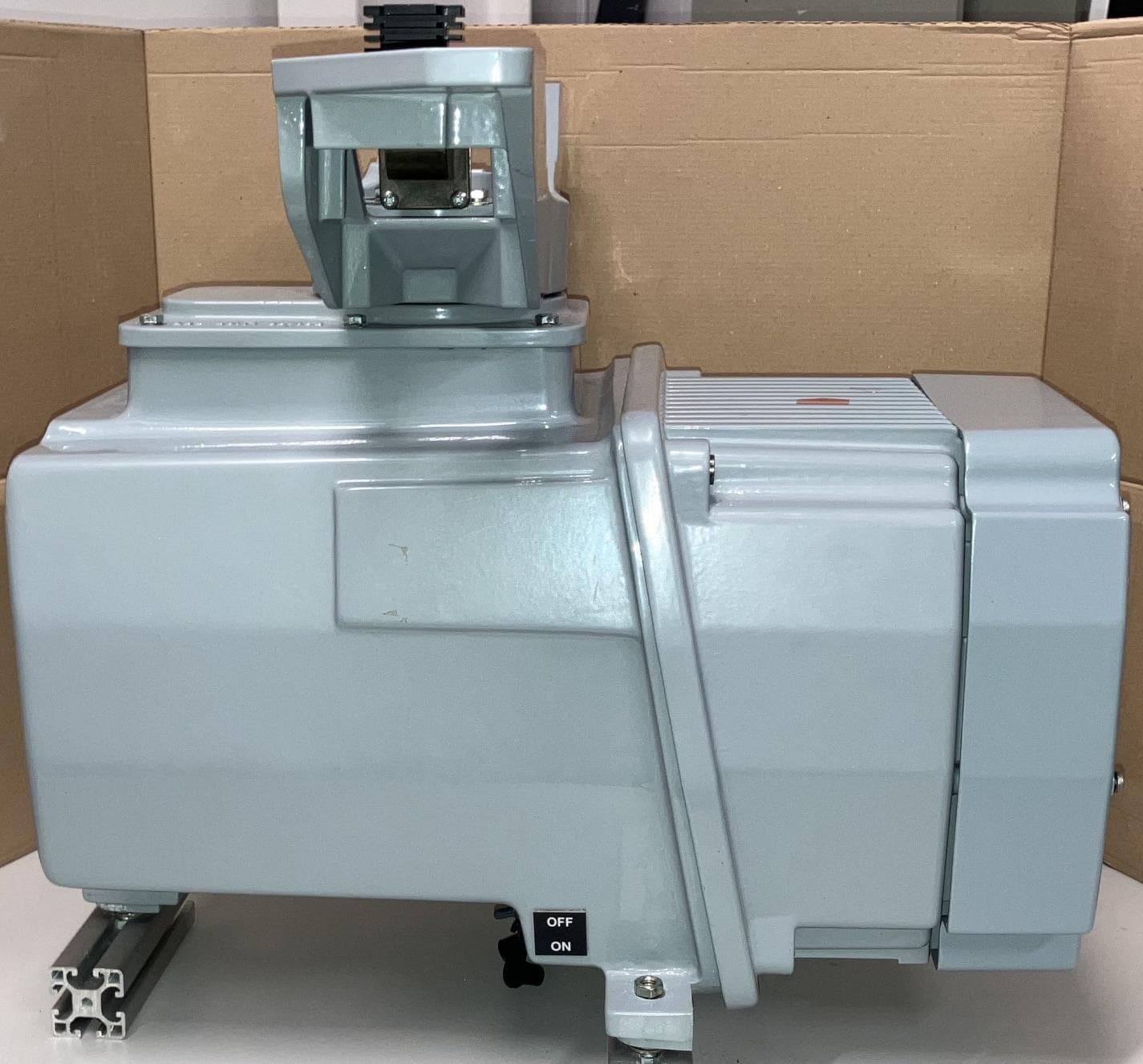
CICPCV-A1
Sep 30, 2024Mk5 Sharp Eye Radar
Equipment Class
MRD - Marine Radar
CICDTX-A613-SF
Aug 25, 2020SHARPEYE RADAR TRANSCEIVER
Equipment Class
TNB - Licensed Non-Broadcast Station Transmitter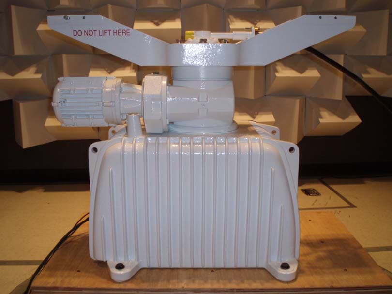
CICDTX-A3-FDLR
May 19, 2015X BAND RADAR
Equipment Class
MRD - Marine Radar
CICDTX-A3
May 09, 2011RADAR
Equipment Class
MRD - Marine Radar
CICCTX-A9
Mar 28, 2002'S' Band Radar
Equipment Class
MRD - Marine Radar