CICCTX-A9'S' Band Radar
Kelvin Hughes Limited
Click to zoom
Application Details
- Equipment Class
- MRD - Marine Radar
- Date of Grant
- Mar 28, 2002
- Application Purpose
- Original Equipment
- Date of Application
- Jan 31, 2002
- Equipment Note
- 'S' Band Radar
- Frequency Range
- 3040.00000000 - 3060.00000000
- Company
- Kelvin Hughes Limited
- Country
- United Kingdom
Documents & Files
Document Text
Text extracted from the exhibit documents filed with the FCC. Open a document above to read the original.
Users Manual
WORKSHOP MANUAL TECHNICAL, INSTALLATION, COMMISSIONING and MAINTENANCE INFORMATION for Mk VII X-BAND TRANSCEIVER and ANTENNAS PUBLICATION KH1251 Issue 1, May 2000 KELVIN HUGHES Kelvin Hughes Ltd. is the Naval and Marine Division of Smiths Industries Aerospace Registered Office: 765 Finchley Road, London NW11 8DS. Incorporated in England No. 1030135 New North Road, Hainault, Ilford, Essex IG6 2UR, England Telephone: 0208 500 1020 Telefax: 0208 559 8522 Telex: 896401 CONFORMITY STATEMENT This equipment has been designed to comply with IMO regulations and IEC standards. COPYRIGHT ãCopyright Kelvin Hughes Ltd. 2000 All rights reserved. No part of this publication may be reproduced, transmitted, transcribed, translated or stored in any form or by any means, without the written permission of Kelvin Hughes Limited. Technical details contained in this publication are subject to change without notice. Page iiIssue 1 CONTENTS PRELIMINARY PAGES Title Page Contents (this page)iii Health and Safety Notice Pageiv Emergency Resuscitationvi Electrostatic Caution Pagevii Amendment Record Pageviii CHAPTERS Chapter 1 - General Description Chapter 2 - Specification Chapter 3 - Technical Introduction Chapter 4 - Installation Chapter 5 - Commissioning Chapter 6 - Technical Description, including Unit Information for: 25 kW FET Modulator (CTX-A369/CTX-A345) Tx Microcontroller PCB (CTX-A346) Logarithmic Receiver PCB (CTX-A356) Azimuth/Heading Line PCB (CAE-A106-2) +26V Motor Starter PCB (CAE-A359) Brushless Motor PCB (CAE-A236) Chapter7-Maintenance Chapter 8 - Parts Annex A - Long Cable Runs Issue 1Page iii IMPORTANT NOTICES HEALTH AND SAFETY 1All personnel are required to study these notices and familiarise themselves with all applicable safety precautions and bring them to the attention of others in the vicinity. HIGH VOLTAGE WARNING LETHAL HIGH VOLTAGES ARE PRESENT IN THE TRANSCEIVER 2A current of 100 mA passing through the human body for one second can kill. This can occur at voltages as low as 35 Vac or 50 Vdc. Some equipment in the system uses electrical power that can be lethal. Whenever practical, before carrying out installation, maintenance or repair, personnel involved must: (1)Isolate the equipment from the electrical supply. (2)Make tests to verify that the isolation is complete. (3)Ensure that power cannot be accidentally reconnected. DO NOT OPEN ANY OF THE UNITS WHEN THE RADAR IS OPERATIONAL - UNLESS FULLY QUALIFIED TO DO SO. 3If it is essential to work on the equipment with power connected, work must only be undertaken by qualified personnel who are fully aware of the danger involved and who have taken adequate safety precautions to avoid contact with dangerous voltages. HEALTH HAZARD 4This equipment contains materials which produce toxic fumes when ignited. 5The inhalation of dust and fumes or any contact with lubricants when cleaning the equipment may be temporarily harmful to health, depending on individual allergic reactions. Components which are broken or overheated may release toxic fumes or dust and must be treated with caution. Do not inhale the fumes and ensure that the dust and debris do not enter open cuts or abrasions. It is prudent to regard all damaged components as being potentially toxic, requiring careful handling and appropriate disposal. Page ivIssue 1 CD-0844 CD-0845 RADIATION HAZARD: NON-IONISING AERIAL RADIATION HAZARD: INJURY CAN RESULT FROM EXPOSURE TO THE MAIN BEAM OF A STATIONARY RADAR AERIAL. DO NOT STAND LESS THAN 2m FROM THE CENTRAL FRONT FACE OF THE AERIAL. 6It is accepted in most countries that no significant hazard is presented by radio frequency mean power density levels up to 10mW/cm. RF power levels in excess of this may cause harmful effects, particularly to the eyes. 7Users of cardiac pacemakers should be aware that radio frequency transmissions, can damage some such devices or cause irregularities in their operation. Persons using a pacemaker should ascertain whether their device is likely to be affected before exposing themselves to the risk of malfunction. SAFETY ALOFT AERIAL ROTATION: BEFORE MAINTENANCE TO THE TURNING MECHANISM TAKES PLACE, DISABLE AERIAL ROTATION. 8When working aloft, ensure that it is brought to the attention of someone in authority at deck or at ground level and that suitably placed warning notices are posted warning that work aloft is in progress. Ensure that the means of access aloft is secure and beware of wet or slippery ladder rungs and working areas. 9When working on or near a radar scanner and other moving or r.f. radiating equipment, ensure that it is switched off and that the fuses have been removed and retained. PERSONAL PROTECTION 10Personal protection must be used whenever the possibility of an uncontrolled hazard exists. For example, a suitable face visor, gloves and a body apron should be worn when handling cathode ray tubes, as a precaution against injury in the event of breakage. Issue 1Page v Page viIssue 1 LOOSEN NECKWARE TILT HEAD BACKWARDS AND PUSH CHIN UPWARDS PINCH THE NOSE COMMENCE VENTILATION FOUR GOOD INFLATIONS MOUTH TO MOUTH IF CHEST DOES NOT RISE RE-CHECK AIRWAY. REMOVE OBSTRUCTION AND RE-INFLATE CHECK PULSE POSITION OF PULSE ONE FIRST AIDER TWO FIRST AIDERS 15 Compressions of 80 per minute followed by two inflations One conducts chest compressions, without pause at 60 per minute. The other administers mouth-to-mouth ventilation - after each 5th compression HEART HAS STOPPED BEATING LAY ON BACK ON FIRM SURFACE eg FLOOR COMMENCE EXTERNAL CHEST COMPRESSION AND CONTINUE MOUTH-TO-MOUTH VENTILATION Check heart beat after first five minutes and then after every three mintutes. Continue external chest compression and mouth-to-mouth ventilation until a normal pulse is felt and colour improves WHEN NORMAL BREATHING COMMENCES PLACE CASUALTY IN RECOVERY POSITION Keep casualty at rest. Remove on a stretcher. Watch closely, particularly for difficulty in breathing. Lightly cover with blankets or other materials. ELECTRIC…
Text truncated - open the document above for the full version.
Block Diagram
Turning Mechanism 8Two versions of turning mechanism are used: (1)Low speed (CAE-A42), which rotates at 25 rpm. (2)High speed (CAE-A41), which rotates at 40 rpm. 9The two versions of turning mechanism use different motors. KH1252 Chapter 1 Page 1.4Issue 2 ANTENNA GEARBOX AZIMUTH PCB RF HEAD MAGNETRON Tx Monitor (OPT) LOGARITHMIC RECEIVER TX MICRO- CONTROLLER PCB VIDEO IF TO/FROM DISPLAY POWER POWER 25 kW FET MODULATOR CD-4029 MOTOR POWER UNIT MAINS INPUT TURNING MECHANISM (CAE-A41 OR CAE-A42) TRANSCEIVER (CTX-A9) EMC FILTER NOISE DIODE (OPT) SAFETY SWITCH CONTROL SOFT START UNIT 3 PHASE MAINS INPUT SYNC Figure 1 - System Block Diagram
Operational Description
CHAPTER 6 TECHNICAL DESCRIPTION INTRODUCTION 1This chapter provides an overview of the Mk VII Downmast Transceiver CTX-A9, and the associated Turning Mechanism, together with functional and technical descriptions for the electronic units. DOWNMAST TRANSCEIVER 2The downmast transceiver is designed for bulkhead mounting inside the vessel. It comprises a sheet metal rear plate which is formed to include the top of the unit. This is braced by two ‘U’ sections which protrude above and below the rear plate to provide the bulkhead fixing points. The main sub-units are bolted to the rear plate (refer to Figure 1). 3The main sub-units are: (1)EMC Filter (2)Power Unit 45-677-124 (3)Electronic Unit consisting of: (a)25 kW FET Modulator CTX-A369/CTX-A345 (b)Tx Microcontroller PCB CTX-A346 (4)Logarithmic Receiver PCB CTX-A356 (5)RF Head CTX-A384 (6)Magnetron (CTX-A309) attached to the RF Head 4Figure 2 shows the interconnections between the units. 5The Electronic Unit has to be removed to gain access to the modulator and pulse transformer. The 25 kW FET Modulator (CTX-A369) consists of a 25 kW Modulator PCB (CTX-A345) mounted on a chassis, together with the high power FETs and a heatsink. 6The EMC Filter is located at the right hand side of the unit and is fitted to the mounting that supports the Electronic Unit. The output terminal 1TB1 is also fitted to this mounting. 7The RF Head is fixed to the top of the framework and is also supported on brackets. 8Two fans are fitted to the Transceiver. One fan (CTX-A379) located at the base of the Electronic Unit provides general purpose cooling for the whole Transceiver. The second fan (45-683-158), fitted to the Electronic Unit heatsink, provides cooling for the modulator components. KH1252 Chapter 6 Issue 2Page 6.3 9A sheet metal wrap-around cover, secured in position by six captive screws, provides access to the front and sides of the unit. Cable entry is at the bottom of the unit. An earth bonding point is situated on the top. POWER SUPPLY (45-677-124) 10The Power Supply is located at the base of the Transceiver and is secured to two mounting brackets by four captive screws. It provides the +27V DC to drive the 300V modulator power supply in the 30 kW Modulator PCB. The +26V or +36V power supplies are not used (required for X band antenna motor only). (1)+27V (2)+15V (3)+10V (Heater Supply) (4)-15V 25 kW FET MODULATOR (CTX-A369/CTX-A345) 11The 25 kW FET Modulator provides the following functions: (1)Drives the S-band 30 kW magnetron. (2)Automatically adjusts the parameters of the magnetron to compensate for the characteristics of different magnetrons, and to allow for change of characteristics due to ageing. 12Full details of this unit are provided in the Unit Information at the end of this chapter. TX MICROCONTROLLER PCB (CTX-A346) 13The main function of the Tx Microcontroller PCB is to interface the Display Unit with the Transceiver. The PCB carries out the following functions: (1)Controls the transmitter via direct parallel connection or Controller Area Network (CAN) bus. (2)Provides control of the FET modulator. (3)Provides modulator trigger pulses of the relevant width and PRF. (4)Provides sync pulses for the receiver and display units. (5)Provides control of the turning motor and modulator cooling fan. (6)Provides the capability of using an external trigger from 300 Hz to 8 kHz, subject to pulse width. The trigger pulse must be positive from 0V. (7)Provides BITE information on the running parameters from the modulator. (8)Provides BITE information on the running parameters of the control board. (9)Controls the pulse width and PRF via a computer serial link. 14Full details of this unit are provided in the Unit Information at the end of this chapter. KH1252 Chapter 6 Page 6.4Issue 2 LOGARITHMIC RECEIVER PCB (CTX-A356) 15The Receiver Assembly (CTX-A364) consists of a Logarithmic Receiver PCB (CTX-A356) mounted on a chassis with a screening cover. The Receiver Assembly is mounted on brackets attached to the main framework and the LNFE. The Logarithmic Receiver PCB provides the following: (1)RF input stages. (2)Logarithmic amplifier with switchable bandwidths. (3)Video detector and amplifier with three independent outputs. (4)Tune indicating and AFC functions. 16Full details of this unit are provided in the Unit Information at the end of this chapter. RF HEAD (CTX-A384) 17The RF Head comprises: (1)Noise Source CAE-A213 (2)Circulator 45-750-0008-001 (3)Diode Limiter 45-646-608 (4)Bandpass Filter 45-750-0009-001 (5)Low Noise Front End CAE-A217, combining and RF amplifier, balanced mixer, electronically tunes local oscillator and IF head amplifier. 18The Magnetron CTX-A309 does not form part of the RF Head, but functionally completes the RF path. High Power (Tx) Signal Path 19Typical pulse conditions for the 30 kW magnetron are: (1)Short pulse: 50 ns at 6 amps (2)Medium pulse: 180 ns at 8.0 amps (3)Long pulse: 800 ns at 8.0 amps (4)Very long pulse: 950 ns at 8.0 amps 20The magnetron output is fed into port 2 of the circulator, and due to the rotational properties of the circulator, emerges at port 3 and out to the rotating joint. 21A small amount of the magnetron energy leaks across the ferrite junction and into the diode limiter. The limiter in turn limits this energy to a safe level for the low noise front end to use as a tune signal. KH1252 Chapter 6 Issue 2Page 6.5 Low Power (Rx) Signal Path 22Signals, which are target returns, are received by the antenna and are fed to port 3 of the circulator, via the rotating joint. The signals emerge at port 1, and are fed to the diode limiter. Normally these signals are of low amplitude, and will not be limited by the diode limiter. The limited signals are passed through an S-band Bandpass Filter and are amplified by the LNFE and mixed at 60MHz, to produce IF for the receiver. KH1252 Chapter 6 Page 6.6Issue 2
Operational Description
CHAPTER 2 SPECIFICATION TECHNICAL SPECIFICATIONS 1The technical specifications for the MkVII S-band Transceiver are as follows: Transmitter: Frequency:3050 ±10 MHz Magnetron Rating:30 kW nominal Magnetron Life:10,000 Hours typical Pulse length and P.R.F: Short(S)nominal 0.055ms 3000pps ±100 Medium(M)nominal 0.2ms 1500 pps ±40 Long(L)nominal 0.9ms 750 pps ±20 Long-Low PRF(VL)nominal 1.0ms 375 pps ±10 Sync. Output:2 x 75 Ohm outputs not less than +12V amplitude Pulse to Pulse Jitter:This will normally be activated and is nominally±15ms from nominal period. This function can be inhibited. The PRF and Pulse Length can be set to other values via the RS232 link. The above values are nominal settings. Receiver specifications are detailed overleaf. KH1252 Chapter 2 Issue 2Page 2.3 Receiver: TypeLogarithmic Receiver I.F.60 MHz Video Output2 x 75W +5.5V to 6V peak signal System Overall Noise FigureNominal 6.0 dB OPERATING TEMPERATURE RANGES Turing Mechanism Ambient Range-25°C to +70°C Humidity95% at +40°C Downmast Transceiver Ambient Range-15°C to +55°C Humidity95% at +40°C FOR TURNING MECHANISM Azimuth Data:180 pulses per revolution Heading Data:1 pulse per revolution INPUT POWER Input Power Single Phase:110V/220V AC input 155 W, 220 VA Input Power Three Phase: Low Speed:0.55 kW 0.75 kVA High Speed:2.2 kW 3 kVA KH1252 Chapter 2 Page 2.4Issue 2
Parts List/Tune Up Info
CHAPTER 5 COMMISSIONING INTRODUCTION 1Interswitched equipments, or equipments interfaced with other radar equipments, are described in their respective Handbooks. CAUTION The transceiver RF output must not be operated into an open circuit or poorly matched feed cable. Damage to the RF head will result. POWER SUPPLIES 2Check that all cables have been installed and connected. 3In the Soft Start Unit check that the thermal overload trip button is set. 4In the Soft Start Unit check the voltage and fuse settings of the Power Supply (factory set to 220V input). For 110V operation, short out the link pins located beside C6 on the PSU. KH1252 Chapter 5 Issue 2Page 5.3 LNE A2 A1 R3** R4** R5## R20** R21** R22## -------- C6 LINKS FUSE CD-1360 Figure 1 - Soft Start Unit: Link and Fuse Locations LINK AND SWITCH SETTINGS 5Ensure that the correct links are fitted to the Display Unit to enable it to work with the MkVII Transceiver. 6The Transceiver links are factory set. The links/switches listed below are options for the installation. All other links and switches are listed in the unit descriptions. Check that the MkVII Transceiver links/switches are set as follows: a) Receiver CTX-A356 LK1OPENTune sample delay (intermediate, approx. 50 ns) LK2MADETune sample delay (maximum, approx. 100 ns) LK3OPENTune sample delay (minimum) Note: only one of LK1, LK2 or LK3 is to be MADE. Selected for best AFC performance) LK5BMinimum AFC Lock A - intermediate AFC lock A &B OPEN - maximum AFC lock b) Tx Microcontroller PCB: Grid SW1-34AONJitter enabled OFFNo PRF jitter SW2-13AOFFAntenna Motor starts on Run ONAntenna Motor on all of the time c) Soft Start Unit neon indicator voltage 220v Nom. Connect a wire link between TP3 and TP4 on PCB (located behind the heatsink). Connect a wire link across one of the two resistors mounted below the keyswitch. 380 to 440V No links required. KH1252 Chapter 5 Page 5.4Issue 2 SETTING TO WORK 7Carry out the following: (1)Switch on the single phase mains at the Isolators for the Display and Transceiver. (2)Set the 3 phase mains isolator to ON. (3)Set the Soft Start Unit switch to ON. (4)Set the display power switch to ON. 8At the display ensure that the Transceiver is entered as MkVII in the installed equipment parameters. 9Verify that the display indicates TX READY after the warm up period of approximately 3 minutes. 10Set to RUN. 11Transceiver status is indicated by LEDs located on the modulator and control board. Only the LEDs on the Tx Microcontroller PCB are visible with the transceiver cover removed. The other LEDs are only visible with the Electronics Unit (CTX-A370) in the test position. Refer to Fault Diagnosis procedures in Chapter 7 details of the LEDs and the test position. 12The LEDs on the Tx Microcontroller PCB are as follows: Grid D188FLit, indicating Tune Indicator signal present (Run mode only) D414EFlashing, indicating that the processor is running D424EOnly lit when external trigger pulses being applied D434ELit, indicating magnetron heater OK Flashes slowly for warm up time Flashes quickly after warm up time D444ENot used KH1252 Chapter 5 Issue 2Page 5.5 HEADING LINE ADJUSTMENT NOTE: This procedure is not required for Nucleus 3 displays. Heading line errors are corrected by the Display ‘skew’ setting. General 13Following installation, the heading line may be checked to give maximum bearing accuracy as follows: NOTE: During the Heading Line alignment procedure, the ship must be stationary on a fixed known heading and must have bearing information from the gyro compass available. The ship is to be alongside; less accurate results are obtained if at anchor or at a buoy. Checking the Alignment 14With the vessel stationary, or at anchor, proceed as follows: (1)Check that the array/gearbox alignment markÙis correct. (2)Switch ON the Display and operate in a HEAD UP mode and at a range of 6 miles. (3)Select a stationary target which can be seen by eye and which paints an echo on the screen. (4)Take a compass bearing on the target, and compare this with the bearing of the echo paint on the display. Note the degree and direction of discrepancy. To Correct an Error (Fine Adjustment) 15Any error is present in the Heading Line may be adjusted as follows: (1)Switch the Gearbox Safety Switch to OFF. (2)Switch all supplies to STANDBY. (3)Using a 12 mm spanner, release the six bolts securing the rear cover to the Turning Mechanism and remove the cover. (4)Loosen the two pillars securing the Azimuth/Heading Line PCB. (5)Hold the antenna secure. (6)Note the position of the pointer on the scale, which is marked in two degree steps. (7)Move the pcb assembly the required amount to correct the mis-alignment. NOTE: Moving the PCB to the left moves the video anti-clockwise with respect to the Heading Line. (8)Retighten the two pillars to secure the Azimuth/Heading Line PCB. (9)Refit the outer cover. DO NOT TIGHTEN. (10)Set the Safety Switch to ON. KH1252 Chapter 5 Page 5.6Issue 2 (11)Set the Display to RUN and check that the visual and PPI display bearing of the known target. (12)To make any further adjustment repeat step (7). (13)Secure the rear cover. To Correct an Error (Coarse Adjustment) 16The Heading Line Opto Disc is factory set, however if the fine adjustment does not achieve the required correction, proceed as follows: (1)Perform Paragraph 15, steps (1) to (3). (2)Disconnect the plug to the Heading Line PCB. (3)Remove the Heading Line PCB, ensuring that the opto sensor does not foul against the opto disc. (4)With the array facing forward, check that the leading edge of the heading line disc recess is in line with the array centre line. (5)The heading line disc recess may be corrected by slackening the three M4 retaining bolts holding the disc in place.Do notremove the bolts completely. (6)Manually rotate the disc to the new position required and retighten the bolts. (7)Refit and reconnect the Heading Line PCB by sliding the opto device over the edge of the opto disc. (8)Refit th…
Text truncated - open the document above for the full version.
Parts List/Tune Up Info
PL4 - Downmast Transceiver CTX-A9: Parts List ITEM NUMBERDESCRIPTIONKELVIN HUGHES Part No. 1ASSEMBLY OF MAGNETRONCTX-A309 2ASSEMBLY OF MkVII RECEIVER, COMPRISINGCTX-A364 MOUNTING CHASSISCTX-1362 COVERCTX-1363 INSULATOR BOARDCTX-1364 LOGARITHMIC RECEIVER PCBCTX-A356 3PART ASSEMBLY OF RF HEAD, COMPRISING:CTX-A384 3ACIRCULATOR45-750-0008-001 3BNOISE SOURCECAE-A213 3CLIMITER45-646-608 3DBANDPASS FILTER S-BAND45-750-0009-001 3ELOW NOISE FRONT ENDCAE-A217 4AIR DEFLECTORCTX-1380 SEAL PLATE UPPERCTX-1264 SEAL PLATE LOWERCTX-1263 SEAL CIRCULATORCTX-1265 FITTING KITCTX-A382 ASSEMBLY OF INSULATING BLOCKCTX-A383 ASSEMBLY OF CABLEFORM, LNFE TO 7-SKACAE-A231 CABLEFORM, RECEIVER, 7-PLE TO 5-PLBCTX-A385 SCREW M5 x 10 PAN HEAD25-243-1055-27 WASHER, CRINKLE M620-282-5010-25 MkVII TRANSMITTER (COMMON)CTX-A374 5POWER SUPPLY TYPE MK4TX45-677-124 6MAINS FILTER 6A TYPE 6ET145-680-003 7FAN 24V DC TYPE 61445-683-158 FAN GUARD METAL LZ28CP45-683-163 8ASSEMBLY OF CABLEFORMCTX-A375 9ASSEMBLY OF MAIN CABLEFORMCTX-A376 10ASSEMBLY OF CABLEFORMCTX-A377 11ASSEMBLY OF CABLEFORMCTX-A378 KH1252 Chapter 8 Issue 2Page 8.9 ITEM NUMBERDESCRIPTIONKELVIN HUGHES Part No. 12ASSEMBLY OF FAN, MKVII TRANSMITTERCTX-A379 FAN 24V DC TYPE 41445-825-0006-001 METAL FAN GUARD LZ 29-145-825-0007-001 ASSEMBLY OF MKVII ELECTRONICS UNITCTX-A370 13ASSEMBLY OF MICROCONTROLLER PCB CTX-A346 14ASSEMBLY OF 25 kW FET MODULATOR CTX-A369 KH1252 Chapter 8 Page 8.10Issue 2 PL4 - Downmast Transceiver CTX-A9: Parts List (continued)
Test Report
FCC ID: CICCTX-A9 MFA p01a0001, d01c0026 D E C L A R A T I O N O F C O N F O R M I T Y of RECEIVER MODEL: CTX-A9 FCC ID: CICCTX-A9 to FEDERAL COMMUNICATIONS COMMISSION Part 15(B) (New) DATE OF REPORT: December 14, 2001 ON THE BEHALF OF THE APPLICANT: Kelvin Hughes Limited AT THE REQUEST OF : P.O. V139928/B5 Kelvin Hughes Limited New North Rd. Hainault, Ilford Essex 1G6 2UR, England Attention of: David A. Hannah, Chief Engineer Dave Everson, Coordinator [email protected] Phone: 011 81 500 1020 FAX: 011 44 208 559 8524 SUPERVISED BY: Morton Flom, P. Eng. FCC ID: CICCTX-A9 MFA p01a0001, d01c0026 TABLE OF CONTENTS RULE DESCRIPTION PAGE 2.948 Description of Measurement Facilities 1 15.109 Receiver Spurious Emissions (Radiated) 6 15.107 A/C Powerline Conducted Emissions 11 FCC ID: CICCTX-A9 MFA p01a0001, d01c0026 PAGE NO. 1 of 17. Required information per ISO/IEC Guide 25-1990, paragraph 13.2: a) TEST REPORT b) Laboratory: (FCC: 31040/SIT) (Canada: IC 2044) M. Flom Associates, Inc. 3356 N. San Marcos Place, Suite 107 Chandler, AZ 85225 c) Report Number: d01c0026 d) Client: Kelvin Hughes Limited New North Rd. Hainault, Ilford Essex 1G6 2UR, England e) Identification: CTX-A9 FCC ID: CICCTX-A9 Description: "S" Band Radar f) EUT Condition: Not required unless specified in individual tests. g) Report Date: December 14, 2001 EUT Received: October 2001 h, j, k): As indicated in individual tests. i) Sampling method: No sampling procedure used. l) Uncertainty: In accordance with MFA internal quality manual. m) Supervised by: Morton Flom, P. Eng. n) Results: The results presented in this report relate only to the item tested. o) Reproduction: This report must not be reproduced, except in full, without written permission from this laboratory. FCC ID: CICCTX-A9 MFA p01a0001, d01c0026 PAGE NO. 2 of 17. M. Flom Associates, Inc. is accredited by the American Association for Laboratory Association (A2LA) as shown in the scope below. "This laboratory is accredited by the American Association for Laboratory Accreditation (A2LA) and the results shown in this report have been determined in accordance with the laboratory's terms of accreditation unless stated otherwise in the report." Should this report contain any data for tests for which we are not accredited, or which have been undertaken by a subcontractor that is not A2LA accredited, such data would not covered by this laboratory's A2LA accreditation. FCC ID: CICCTX-A9 MFA p01a0001, d01c0026 PAGE NO. 3 of 17. GENERAL INFORMATION Part 2.948: (a)(b) DESCRIPTION OF MEASUREMENT FACILITIES: FILE: 31040/SIT A description of the measurement facilities was filed with the Commission and was found to be in compliance with the requirements of Section 2.948, by letter dated March 13, 2000. All pertinent changes will be reported to the Commission by up-date prior to March 2003. (b)(4) SUPPORTING STRUCTURES: SKETCH - ATTACHED EXHIBITS (b)(5)(6) TEST INSTRUMENTATION: LIST - SEE EXHIBITS 2.925: IDENTIFICATION OF AN AUTHORIZED DEVICE: DRAWING - SEE EXHIBITS LOCATION OF LABEL - SEE PHOTOS NAME AND ADDRESS OF APPLICANT : Kelvin Hughes Limited New North Rd. Hainault, Ilford Essex 1G6 2UR, England FCC ID: CICCTX-A9 MFA p01a0001, d01c0026 PAGE NO. 4 of 17. 2.911: 2.1033(b)(6) TECHNICAL REPORT MANUFACTURER: Kelvin Hughes Limited New North Rd. Hainault, Ilford Essex 1G6 2UR, England TRADE NAME: Kelvin Hughes LTD FCC ID: CICCTX-A9 MODEL NO: CTX-A9 PHOTOGRAPHS: SEE LIST OF EXHIBITS DUT DESCRIPTION : This unit Passes 15.31: MEASUREMENT STANDARD & PROCEDURE: IEEE STANDARD 187 WAS USED AS A GUIDE. FCC MEASUREMENT PROCEDURE MP-1 x ANSI 63.4 (1992/2000) “Methods of measurement od radio-noise emissions from low-voltage electrical and electronic equipment in the range of 9 kHz to 40 GHz.” FCC ID: CICCTX-A9 MFA p01a0001, d01c0026 PAGE NO. 5 of 17. EXPOSITORY STATEMENT 1. NUMBER OF BANDS = 1 2. NUMBER OF CHANNELS = 1 3. TUNING RANGE, MHz = 3040 to 3060 4. OSCILLATOR RANGE, MHz = 3100 to 4200 5. I.F., MHz = 60 6. BLOCK DIAGRAM = ATTACHED 7. For cellular receiver only, the radio transceiver meets the requirements of FCC Bulletin OET 53 ("Cellular System Mobile Stations-Land-System Compatibility Specification."). See attached affidavit. 15.203 : ANTENNA REQUIREMENT: The antenna is permanently attached to the EUT The antenna uses a unique coupling x The EUT must be professionally installed The antenna requirement does not apply SUPERVISED BY: Morton Flom, P. Eng. FCC ID: CICCTX-A9 MFA p01a0001, d01c0026 PAGE NO. 6 of 17. NAME OF TEST: Receiver Spurious Emissions (Radiated) SPECIFICATION: 15.109: Radiated Interference Limits 15.33: Frequency Range of Radiated Measurements 80.217: Suppression of Interference Aboard Ships GUIDE: See measurement procedure below TEST CONDITIONS: Standard Temperature & Humidity TEST EQUIPMENT: As per attached page SEARCH ANTENNAS: 100 Hz - 50 MHz: Emco 3301B Active Rod 10 kHz - 32 MHz: Singer 94593-1 Loop 25 MHz - 300 MHz: Emco 3109 Biconical 200 MHz - 1 GHz: Aprel 2001 Log Periodic 1 GHz - 18 GHz: Emco 3115 Horn 10 GHz - 40 GHz: Emco 3116 Horn with HP11970A Mixer MEASUREMENT PROCEDURE 1. At first, bench tests were performed to locate the spurious emissions at the antenna terminals. 2. In the field, tests were conducted over the range shown, The test sample was set up on a wooden turntable above ground, and at a distance of three meters from the antenna connected tot he Spectrum Analyzer. 3. In order to obtain the maximum response at each frequency, the turntable was rotated, and the search antenna was raised and lowered. The EUT was also adjusted for maximum response. Tests were conducted in Horizontal & Vertical polarization modes. 4. The field strength was calculated from: E μV/m @ 3 m = Log 10 -1 (dBμV + A.F. + C.L.) 20 5. MEASUREMENT RESULTS: Attached for "Worst Case" conditions. FCC ID: CICCTX-A9 MFA p01a0001, d01c0026 PAGE NO. 7 of 17. RADIATED TEST SETUP NOTES: (a)Search Antenna - Rotatable on boom (b) Non-metallic boom (c) Non-metallic mast (d) Ad…
Text truncated - open the document above for the full version.
Test Report
FCC ID: CICCTX-A9 MFA p01a0001, d01c0057 Date of Report: Date of Submission: December 14, 2001 January 31, 2002 Federal Communications Commission Via Electronic Filing Attention: Authorization & Evaluation Division Applicant: Kelvin Hughes Limited Equipment: CTX-A9 FCC ID: CICCTX-A9 FCC Rules: 80 Gentlemen: On behalf of the Applicant, enclosed please find Application Form 731, Engineering Test Report and all pertinent documentation, the whole for approval of the referenced equipment as shown. Filing fees are attached. We trust the same is in order. Should you need any further information, kindly contact the writer who is authorized to act as agent. Sincerely yours, Morton Flom, P. Eng. enclosure(s) cc: Applicant MF/cvr FCC ID: CICCTX-A9 MFA p01a0001, d01c0057 LIST OF EXHIBITS (FCC CERTIFICATION (TRANSMITTERS) - REVISED 9/28/98) APPLICANT: Kelvin Hughes Limited FCC ID: CICCTX-A9 BY APPLICANT: 1. LETTER OF AUTHORIZATION x 2. IDENTIFICATION DRAWINGS, 2.1033(c)(11) x LABEL x LOCATION OF LABEL x COMPLIANCE STATEMENT x LOCATION OF COMPLIANCE STATEMENT 3. PHOTOGRAPHS, 2.1033(c)(12) x 4. DOCUMENTATION: 2.1033(c) (3) INSTALLATION MANUAL x (9) TUNE-UP/ALIGNMENT PROCEDURE x (10) SCHEMATIC DIAGRAM x (10) OPERATIONAL DESCRIPTION x BLOCK DIAGRAM x PARTS LIST x ACTIVE DEVICES x 5. PART 80.203(b) ATTESTATION x BY M.F.A. INC. A. TESTIMONIAL & STATEMENT OF CERTIFICATION B. STATEMENT OF QUALIFICATIONS FCC ID: CICCTX-A9 MFA p01a0001, d01c0057 T R A N S M I T T E R C E R T I F I C A T I O N of FCC ID: CICCTX-A9 MODEL: CTX-A9 to FEDERAL COMMUNICATIONS COMMISSION Rule Part(s) 80 DATE OF REPORT: December 14, 2001 ON THE BEHALF OF THE APPLICANT: Kelvin Hughes Limited AT THE REQUEST OF : P.O. V139928/B5 Kelvin Hughes Limited New North Rd. Hainault, Ilford Essex 1G6 2UR, England Attention of: David A. Hannah, Chief Engineer Dave Everson, Coordinator [email protected] Phone: 011 81 500 1020 FAX: 011 44 208 559 8524 SUPERVISED BY: Morton Flom, P. Eng. FCC ID: CICCTX-A9 MFA p01a0001, d01c0057 THE APPLICANT HAS BEEN CAUTIONED AS TO THE FOLLOWING: 15.21 INFORMATION TO USER. The users manual or instruction manual for an intentional radiator shall caution the user that changes or modifications not expressly approved by the party responsible for compliance could void the user's authority to operate the equipment. 15.27(a) SPECIAL ACCESSORIES. Equipment marketed to a consumer must be capable of complying with the necessary regulations in the configuration in which the equipment is marketed. Where special accessories, such as shielded cables and/or special connectors are required to enable an uninte…
Text truncated - open the document above for the full version.
Contact Information
Applicant
Tim Acland(Chief Engineer)
Technical Contact
M. Flom Associates, Inc.Morton Flom
[email protected]480-926-3100
3356 N. San Marcos Place, Suite 107 · Chandler, Arizona · United States
Non-Technical Contact
M. Flom Associates, Inc.Morton Flom
[email protected]480-926-3100
Test Firm
M. Flom Associates, Inc.Morton Flom
Technical Specifications
| # | Rule Parts | Frequency Range | Power Output | Emission | Tolerance |
|---|---|---|---|---|---|
| 1 | 80 | 3.04 GHz - 3.06 GHz | 30000 W | 25M8P0N | 10000.0000000000 Hz |
Other Applications from Kelvin Hughes Limited
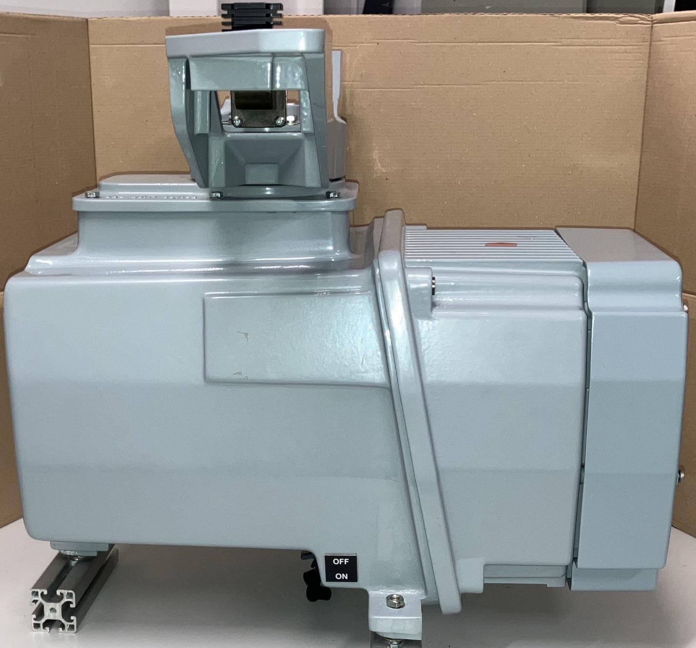
CICPCV-A1
Sep 30, 2024Mk5 Sharp Eye Radar
Equipment Class
MRD - Marine Radar
CICDTX-A613-SF
Aug 25, 2020SHARPEYE RADAR TRANSCEIVER
Equipment Class
TNB - Licensed Non-Broadcast Station Transmitter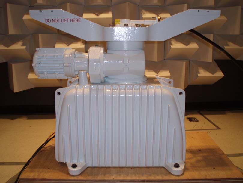
CICDTX-A3-FDLR
May 19, 2015X BAND RADAR
Equipment Class
MRD - Marine Radar
CICDTX-A3
May 09, 2011RADAR
Equipment Class
MRD - Marine Radar
CICCAE-A30-7
Mar 28, 2002'X' Band Radar
Equipment Class
MRD - Marine Radar