CICPCV-A1Mk5 Sharp Eye Radar
Kelvin Hughes Limited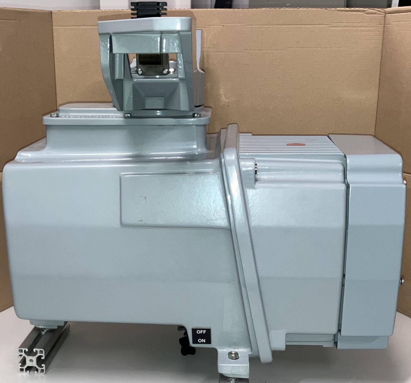
Click to zoom
Application Details
- Equipment Class
- MRD - Marine Radar
- Date of Grant
- Sep 30, 2024
- Application Purpose
- Original Equipment
- Date of Application
- Sep 30, 2024
- Equipment Note
- Mk5 Sharp Eye Radar
- Frequency Range
- 9200.00000000 - 9500.00000000
- Company
- Kelvin Hughes Limited
- Country
- United Kingdom
Documents & Files
Document Text
Text extracted from the exhibit documents filed with the FCC. Open a document above to read the original.
Users Manual
Kelvin Hughes MK5 SharpEye Chapter 6: Commissioning/ Setting to work Page 31 of 76 KH2200 Issue 4 6 Commissioning/ Setting to work Overview No commissioning is required at or within the transceiver. The system is configured via the display sub-system or via a laptop computer connected to the relevant managed network switch. The procedures noted in this handbook do not detail the configuration of firewall or antivirus software on computing equipment. HENSOLDT UK can only offer technical assistance with the parameters directly related to the configuration of the Kelvin Hughes MK5 SharpEye transceiver. COMMISSIONING WEB PAGE In most applications it will NOT be necessary to access the commissioning web page. Parameters within the web page must only be adjusted when specifically advised by HENSOLDT UK or as part of a system integration instructions. CONFIGURATION: HENSOLDT UK SYSTEMS For Kelvin Hughes display solutions, a list of applicable IP addresses, TCP, UDP Port configurations etc. can be found in the relevant display commissioning handbook. CONFIGURATION: 3 RD PARTY SYSTEMS The system configuration will be set by the system integrator. The various settings should be confirmed prior to commencing this task. HELP/ CONTEXT HELP With the cursor hovering over some buttons or functions within the webpage, CONTEXT HELP/ SETTINGS GUIDANCE will be temporarily displayed on the right hand side of the web page. The help guidance includes details about the function and suggested settings. COMMON WEB PAGE FUNCTIONS FUNCTION OVERVIEW/ DESCRIPTION SAVE Saves the current setting(s). Changes are not adopted until SAVE is pressed. When SAVE is pressed, warnings are presented. When changing IP address details the system may automatically re-boot. SAVED OK When a change has been successfully saved, a green confirmation message is displayed at the base of the webpage. SAVE ERROR If there is an error with a setting or parameter. A red error message is displayed at the base of the webpage. RESET Resets the page setting(s) to the factory defaults. +/- Minimise/ maximise the details in a tab. Return to the Main Menu (Back arrow). A function or setting is ON, enabled, locked etc. A function or setting is OFF, disabled, unlocked etc. A function or feature is selected. A function or feature is NOT selected. Hover over any status indicators to open the Help/ Context help function that describes the colour status of each indicator. Kelvin Hughes MK5 SharpEye Chapter 6: Commissioning/ Setting to work Page 32 of 76 KH2200 Issue 4 System configuration When access to the commission pages is required, connect a laptop computer to the managed network switch specifically associated with the Kelvin Hughes MK5 SharpEye being commissioned, open a web browser and enter the default IP address shown below. A web page will open that has a number of tabs which are detailed in the following pages. FACTORY DEFAULT IP ADDRESS http://192.168.22.70:8008 Where a setting, value or configuration has not been defined by the system integrator, the setting should be left at the factory default value. IP Tab IP ADMINISTRATION PAGE (LOCKED/ UNLOCKED) The IP address/ Subnet Mask sections of the IP Tab are locked by default via a separate IP Administration page. The method of unlocking the IP address/ subnet mask is not detailed in this handbook. Please contact HENSOLDT UK or the system integrator for details on accessing the IP Administration page. IP tab LOCKED (see note above) IP Tab UNLOCKED IP TAB The IP tab is used to set the various IP address as defined by the system handbook or system integrator. a) To change the IP address firstly unlock the page (see above), b) Enter the required details and press the Save button, c) When Save is pressed, the system will automatically reboot, d) Where an IP address has been changed, the new IP address will have to be entered to re-open the web page, e) Lock the IP address in the Administration page. Kelvin Hughes MK5 SharpEye Chapter 6: Commissioning/ Setting to work Page 33 of 76 KH2200 Issue 4 IP Advanced tab IP Advanced tab MINIMISED CONFIGURATION The IP tab is used to set the advanced IP details as defined by the relevant display handbook or the system integrator. The Tab can be displayed Minimised or Maximised as shown. a) Enter the required details and press the Save button. b) Reset reverts the settings to the factory defaults. IP Advanced tab MAXIMISED TAB COLOUR When viewing the page Minimised, the selected tab is highlighted in Green as shown in the Control tab above. ASTERIX tab The ASTERIX tab is used to configure the networking as defined by the relevant display handbook or the system integrator. ASTERIX Custom tab The ASTERIX custom tab is used to configure the Video Summary Message (VSM) as defined by the display handbook or system integrator. Kelvin Hughes MK5 SharpEye Chapter 6: Commissioning/ Setting to work Page 34 of 76 KH2200 Issue 4 Transmit control HEADING LINE SKEW (HLS) ADJUSTMENT See Disable HLS updates below before attempting this configuration. a) Where possible and in the relevant radar setup/ configuration menu, make a note of the current SharpEye transmission frequency then set the frequency to the LOWEST available value. b) From the radar screen, calculate the level of heading line skew required. c) Enter the required heading line skew in degrees in the box marked Heading Line Skew (HLS) and press Save. FREQUENCY SKEW (SQUINT) a) In the relevant radar setup menu, set the SharpEye transmission frequency to the HIGHEST available value. b) Observing the radar screen, adjust the Frequency Squint value so that the radar returns correctly align with the heading line. Values of between -3 to +3° can be entered. c) To observe a change on the radar screen, you will need to press Save after entering each value. d) When the returns are correctly aligned, press Save. e) In the relevant radar Setup page, return the SharpEye transmission frequency to the original transmission frequen…
Text truncated - open the document above for the full version.
Users Manual
Kelvin Hughes MK5 SharpEye Upmast X-band transceiver INSTALLATION, COMMISSIONING, OPERATION & MAINTENANCE KH-2200 issue 4 Kelvin Hughes MK5 SharpEye Chapter 1: Contents Page 2 of 76 KH2200 Issue 4 DOCUMENT HISTORY ISSUE RELEASE DATE DETAILS 1 November 2019 First release. 2 February 2020 Addition of Corrective Maintenance section, Service Access Panel safety rope and carabiner added to fitting kit and assembly instructions, Minor corrections, amendments and drawings updated to latest revision(s). 3 July 2021 Section 4.1.6: Fitting kit contents revised. Section 4.5: Update to transceiver mounting arrangement Section 5.2: Connector location drawing updated (PLA & PLB). Drawings updated to latest revision(s) as appropriate. Minor corrections and amendments. 4 February 2024 FCC Warnings added. Copyright © 2024 HENSOLDT UK. HENSOLDT, its logo and the product names are registered Trademarks. All rights reserved. When planning any aspect of the installation, commissioning, operation, maintenance or risk analysis (RADHAZ) of the system(s) described in this handbook, it is the responsibility of the individual carrying out the required task to ensure they are working from the latest issue/ revision of this document. No parts of this publication may be reproduced, transmitted, transcribed, translated or stored in any form or by any means without the written permission of HENSOLDT UK. Where translated, the original English version of this document will remain the definitive document and should be referred to in any situation of doubt, confusion or conflict. Specifications are subject to change without notice. Printed copies of this document are unmaintained. This publication supersedes all previous versions. Kelvin Hughes MK5 SharpEye Chapter 1: Contents Page 3 of 76 KH2200 Issue 4 1 Contents 1 Contents ........................................................... 3 2 Safety notices .................................................. 5 3 Introduction ..................................................... 9 Overview ...................................................... 9 Part numbers ............................................... 9 Typical system ........................................... 10 4 Mechanical installation ................................. 11 Installation considerations & requirements 11 Storage conditions & shelf life ................... 11 Handbook: Radar installation guidelines ... 11 General position requirements .................. 11 Recommended orientation ........................ 13 Inspection & installation notes ................... 13 Fitting kits, cables & tools .......................... 13 Recommended tools ................................. 14 Torque settings.......................................... 14 Unpacking & lifting ..................................... 15 X-band LPA antenna installation ............... 16 Lifting ......................................................... 18 Turning unit/ transceiver installation .......... 19 Dimensions ................................................ 20 Mounting footprint ...................................... 20 1.3m Antenna ............................................ 21 1.9m antenna ............................................ 22 2.5m antenna ............................................ 23 PCV-A2 AC/DC converter ......................... 24 5 Termination .................................................... 25 Cabling, termination and general notes..... 25 Connector & Switch locations .................... 26 Earth stud .................................................. 26 PCV-A137-* DC cable ............................... 27 SCV-A168-* LAN cable ............................. 28 PCV-A2 AC/DC supply (optional) .............. 29 External fan connection ............................. 30 6 Commissioning/ Setting to work ................. 31 Overview .................................................... 31 System configuration ................................. 32 IP Tab ........................................................ 32 IP Advanced tab ........................................ 33 ASTERIX tab ............................................. 33 ASTERIX Custom tab ................................ 33 Transmit control......................................... 34 Sectors ...................................................... 35 Fan status & configuration ......................... 36 Status and Version tabs ............................ 36 Printer output/ system configuration .......... 36 7 Installation checklist .................................... 39 8 Operator instructions ................................... 41 Power ON, OFF & system isolation .......... 41 Control & operation ................................... 41 Operational states ..................................... 41 .................................... 42 Fan operation ............................................ 43 System reset ............................................. 43 Optional AC/DC power supply. ................. 43 Interpreting the Radar display ................... 43 9 Maintenance .................................................. 45 IMPORTANT MAINTENANCE NOTES .... 45 Planned maintenance ............................... 46 6-monthly planned maintenance ............... 46 5 years: External fan replacement ............ 47 5 years: Internal fan replacement ............. 48 Illustrated Parts List ................................... 49 Corrective maintenance ............................ 52 Troubleshooting ........................................ 52 General precautions and notes ................. 55 Fan & Outer Cover removal ...................... 55 Transceiver removal ................................. 57 PSU fuse .................................................. 59 EMC filter (PCV-A128) .............................. 60 PSU assembly (PCV-A129) ...................... 61 Motor Controller (CAE-A429-1)................. 63 HL/ AZ encoder (PCA-A105) .................... 65 HL/AZ dis…
Text truncated - open the document above for the full version.
Attestation Statements
�.,_ Gll/-.;� ,,. ARMED ,o�cu COVENANT �, HEI\ISOLDT Detect and Protect. ./ /. HENSOLDT UK Voltage, Mollison Avenue Enfield EN3 7XCl, United Kingdom T +44 (0)1992 805200 F +44 (0)1992 805310 www.uk.hensoldt.net Federal Communications Commission Authorization and Evaluation Division 74 35 Oakland Mills Road Columbi a, MD 21046 USA Date: 31 October 2023 Ref: Attestation Statements Part 2.911(d)(S)(ii) Filing FCC ID: CICPCV-A1, FRN 0019158021 Ke lvin Hughes Limited (Trading as Hensoldt UK) ("the applicant") certifies that, as of the date of the filing of the application, the applicant is not iden tified on the Covered List (as a specifically named entity or any of its subsidiaries or affiliates) an entity producing "covered" equipment. Sincerely, Tim Acland HENSOLDT UK, a trading name of Kelvin Hughes Limited Registered Office: Voltage, Mollison Avenue, Enfield EN3 7XO, UK Incorporated in England and Wales No: 01030135
Attestation Statements
�.,_ Gll/-.;� ,,. ARMED ,o�cu COVENANT �, HEI\ISOLDT Detect and Protect. ./ /. HENSOLDT UK Voltage, Mollison Avenue Enfield EN3 7XCl, United Kingdom T +44 (0)1992 805200 F +44 (0)1992 805310 www.uk.hensoldt.net Federal Communications Commission Authorization and Evaluation Division 74 35 Oakland Mills Road Columbia, MD 21046 USA Date: 31 Octob er 2023 Ref: Attestation Statements Part 2.911(d)(S)(i) Filing FCC ID: CICPCV-A1, FRN 0019158021 Kelvin Hughes Limited (Trading as Hensoldt UK) ("the applicant") certifies that the equipment for which authorization is sought is not "Covered" equipment prohibited from receiving an eq uipment authorization pursuant to section 2.903 of the FCC rules. S incerely, Tim Acland HENSOLDT UK, a trading name of Kelvin Hughes Limited Registered Office: Voltage, Mollison Avenue, Enfield EN3 7XO, UK Incorporated in England and Wales No: 01030135
External Photos
External Photos for FCC Submission FCC ID: CICPCV-A1 External - Front External - Front Side Right External - Back External - Front Side Left External - Above External - Below External - Close up of Connectors
ID Label/Location Info
FCC Label & Location for FCC Submission FCC ID: CICPCV-A1 Proposed Location of FCC/IC Label
Internal Photos
Internal Photos for FCC Submission FCC ID: CICPCV-A1 Internal of Mk5 Unit – SharpEye Assembly pulled out Internal – (Top) PCV-A128 EMC Filter PCA, (Bottom) PCV-A101 Power Supply Board Internal – SCV A113 Downconverter (PCB 001335-1, -2, -3) Internal - SCV A113 Downconverter (rear PCB 001335-1) Internal – SCV HPA (PCB 001359-3, -4, 001360-1, -2, rear 001362) Internal – SCV HPA (PCB 001362) Internal – SCV LNA (PCB 001361) Internal – SCV LNA (PCB 001359-1) Internal – SCV LNA (PCB 001359-2) Internal – SCV Synth/PLO (PCB 001359-5, -6, -8, 001336-1, -2 ) Internal – SCV Upconverter (PCB 001334-1, -2, -3, 001359-7, -9 )
RF Exposure Info
Test Report# TR_6172-23_FCC 1.1310/ MPE_ Revision: 3 Te s t Report - FCC Par t 1.1310/ MPE Applicant: HENSOLDT UK, a trading name of Kelvin Hughes Limited This test report relates only to the items tested as identified and is not valid for any subsequent changes or modifications made to the equipment under test. 13146 NW 86 th Drive, Suite 400, Alachua, Florida 32615 (352) 472-5500 / [email protected] Page 2 of 10 This test report shall not be reproduced except in full without the written and signed permission of Timco Engineering Inc., a subsidiary of Industrial Inspection & Analysis, Inc. (IIA). Table of Contents 1. APPLICANT INFORMATION ........................................................................................................................................................................... 3 2. LOCATION OF TESTING ................................................................................................................................................................................. 3 2.1 TEST LABORATORY ...................................................................................................................................................................... 3 2.2 TESTING WAS PERFORMED, REVIEWED BY .................................................................................................................................... 4 3. TEST SAMPLE(S) (EUT/DUT) ........................................................................................................................................................................... 5 3.1 DESCRIPTION OF THE EUT .......................................................................................................................................................... 5 4. TEST METHODS & APPLICABLE REGULATORY LIMITS ............................................................................................................................ 6 4.1 TEST METHODS/STANDARDS/GUIDANCE: .................................................................................................................................... 6 4.1.1 FCC Limits for Maximum Permissible Exposure (MPE) .......................................................................................... 6 4.2 EQUATIONS ................................................................................................................................................................................ 7 5. RF EXPOSURE RESULTS .................................................................................................................................................................................. 8 6. HISTORY OF TEST REPORT CHANGES ........................................................................................................................................................ 9 13146 NW 86 th Drive, Suite 400, Alachua, Florida 32615 (352) 472-5500 / [email protected] Page 3 of 10 This test report shall not be reproduced except in full without the written and signed permission of Timco Engineering Inc., a subsidiary of Industrial Inspection & Analysis, Inc. (IIA). 1. Applicant Information Applicant: HENSOLDT UK, a trading name of Kelvin Hughes Limited Address: Voltage, Mollison Avenue Enfield, ESSEX, EN3 7XQ United Kingdom 2. Location of Testing 2.1 Test Laboratory Timco Engineering Inc. is a subsidiary of Industrial Inspection & Analysis, Inc. (“IIA”). Testing was performed at IIA’s permanent laboratory located at 13146 NW 86 th Drive, Suite 400, Alachua, Florida 32615. FCC test firm # 578780 FCC Designation # US1070 FCC site registration is under A2LA certificate # 0955.01 ISED Canada test site registration # 2056A EU Notified Body # 1177 For all designations see A2LA scope # 0955.01 13146 NW 86 th Drive, Suite 400, Alachua, Florida 32615 (352) 472-5500 / [email protected] Page 4 of 10 This test report shall not be reproduced except in full without the written and signed permission of Timco Engineering Inc., a subsidiary of Industrial Inspection & Analysis, Inc. (IIA). 2.2 Testing was performed, reviewed by Dates of Testing: 01/16/2023 – 03/23/2023 Signature: Name & Title: Tim Royer, EMC Engineer Date of Signature 04/26/2023 13146 NW 86 th Drive, Suite 400, Alachua, Florida 32615 (352) 472-5500 / [email protected] Page 5 of 10 This test report shall not be reproduced except in full without the written and signed permission of Timco Engineering Inc., a subsidiary of Industrial Inspection & Analysis, Inc. (IIA). 3. Test Sample(s) (EUT/DUT) The test sample was received: 01/16/2023 3.1 Description of the EUT A description as well as unambiguous identification of the EUT(s) tested. Where more than one sample is required for technical reasons (such as the use of connected units for the purpose of conducted output power testing where the product units will have integral antennas), each specific test shall identify which unit was tested. Identification FCC ID: CICPCV-A1 Brief Description Mk5 Sharp Eye Radar Model(s) # Mk5 Sharp Eye Firmware version n/a Software version ZM-2924 Version 1.3 Technical Characteristics Frequency Range 9.1 – 9.5 GHz RF O/P Power (Max.) 62.8 W/ Nominal peak output power into the antenna of 80 W Modulation FM Pulse/FM Chirp Bandwidth & Emission Class 53M5PON Number of Channels 14 Duty Cycle 6NM 4.26%, 12NM 7.90%, 24NM 7.59% Antenna Connector Flange Voltage Rating (AC or Batt.) 28V DC Antenna Characteristics Antenna Frequency Range Mode / BW Antenna Gain 1 n/a n/a 0 dBi - Note: Information such as antenna gain, firmware/software numbers are provided by manufacturer and cannot be validated by the test lab. 13146 NW 86 th Drive, Suite 400, Alachua, Florida 32615 (352) 472-5500 / [email protected] Page 6 of 10 This test report shall not be reproduced except in full without the written and signed permission of Timco Engineering Inc., a subsidiary of Industrial Inspection & Analysis, Inc. (IIA). 4. Test method…
Text truncated - open the document above for the full version.
Test Report
Test Report# TR_6172-23_FCC 80_Radar_ Revision: 2 Test Report - FCC Par t 80 (Radar) Applicant: HENSOLDT UK, a trading name of Kelvin Hughes Limited This test report shall not be reproduced except in full without the written and signed permission of Timco Engineering Inc. (IIA). This test report relates only to the items tested as identified and is not valid for any subsequent changes or modifications made to the equipment under test. 13146 NW 86 th Drive, Suite 400, Alachua, Florida 32615 (352) 472-5500 / [email protected] Page 2 of 82 This test report shall not be reproduced except in full without the written and signed permission of Timco Engineering Inc. (IIA). Table of Contents 1. APPLICANT INFORMATION ........................................................................................................................................................................... 5 1.1 PART 80 TEST RESULT SUMMARY ............................................................................................................................................................................ 5 2. LOCATION OF TESTING ................................................................................................................................................................................. 6 2.1 TEST LABORATORY .................................................................................................................................................................................................... 6 2.2 TESTING WAS PERFORMED, REVIEWED BY ................................................................................................................................................................ 6 3. TEST SAMPLE(S) (EUT/DUT) ........................................................................................................................................................................... 7 3.1 DESCRIPTION OF THE EUT ........................................................................................................................................................................................ 7 3.2 CONFIGURATION OF EUT ......................................................................................................................................................................................... 8 3.3 TEST SETUP OF EUT .................................................................................................................................................................................................. 8 4. TEST METHODS & APPLICABLE REGULATORY LIMITS ............................................................................................................................ 9 4.1 TEST METHODS/STANDARDS/GUIDANCE: ............................................................................................................................................................... 9 4.2 APPLIED LIMITS AND REGULATORY LIMITS: .............................................................................................................................................................. 9 5. MEASUREMENT UNCERTAINTY .................................................................................................................................................................... 9 6. ENVIRONMENTAL CONDITIONS ................................................................................................................................................................. 9 6.1 TEMPERATURE & HUMIDITY ...................................................................................................................................................................................... 9 7. LIST OF TEST EQUIPMENT AND TEST FACILITY ...................................................................................................................................... 10 7.1 LIST OF TEST EQUIPMENT ....................................................................................................................................................................................... 10 8. TEST RESULTS .................................................................................................................................................................................................. 11 8.1 POWER AT THE FINAL AMPLIFIER ............................................................................................................................................................................ 12 8.2 RF OUTPUT POWER ................................................................................................................................................................................................ 13 8.2.1 RF Power Output Plot, 9180 MHz, High Power ............................................................................................................................. 14 8.2.2 RF Power Output Plot, 9180 MHz, Low Power ............................................................................................................................... 15 8.2.3 RF Power Output Plot, 9260 MHz, High Power ............................................................................................................................. 16 8.2.4 RF Power Output Plot, 9260 MHz, Low Power .............................................................................................................................. 17 8.2.5 RF Power Output Plot, 9340 MHz, High Power ............................................................................................................................. 18 8.2.6 RF Power Output Plot, 9340 MHz, Low Power .............................................................................................................................. 19 8.2.7 RF Power Output Plot, 9440 MHz, High Power ...............................................................................................…
Text truncated - open the document above for the full version.
Test Setup Photos
ANNEX B – Test Setup Photograph Exhibit FCC ID: CICPCV-A1 Radiated Testing, Below 1 GHz Radiated Testing, Below 1 GHz #2 Radiated Testing, Above 1 GHz
Contact Information
Applicant
Tim Acland(Chief Technology Officer)
Test Firm
Timco Engineering, Inc.Bruno Clavier
Technical Specifications
| # | Rule Parts | Frequency Range | Power Output | Emission | Tolerance |
|---|---|---|---|---|---|
| 1 | 80 | 9.20 GHz - 9.50 GHz | 80 W | 53M5P0N | 17.2000000000 ppm |
Other Applications from Kelvin Hughes Limited

CICDTX-A613-SF
Aug 25, 2020SHARPEYE RADAR TRANSCEIVER
Equipment Class
TNB - Licensed Non-Broadcast Station Transmitter
CICDTX-A3-FDLR
May 19, 2015X BAND RADAR
Equipment Class
MRD - Marine Radar
CICDTX-A3
May 09, 2011RADAR
Equipment Class
MRD - Marine Radar
CICCTX-A9
Mar 28, 2002'S' Band Radar
Equipment Class
MRD - Marine Radar
CICCAE-A30-7
Mar 28, 2002'X' Band Radar
Equipment Class
MRD - Marine Radar