CICCTX-A8'X' Band Radar
Kelvin Hughes Limited
Click to zoom
Application Details
- Equipment Class
- MRD - Marine Radar
- Date of Grant
- Mar 28, 2002
- Application Purpose
- Original Equipment
- Date of Application
- Jan 30, 2002
- Equipment Note
- 'X' Band Radar
- Frequency Range
- 9110.00000000 - 9710.00000000
- Company
- Kelvin Hughes Limited
- Country
- United Kingdom
Documents & Files
Document Text
Text extracted from the exhibit documents filed with the FCC. Open a document above to read the original.
Users Manual
INSTALLATION OF UPMAST X-BAND TRANSCEIVER CAE-A12-20 (25kW) GENERAL 8The Upmast Transceiver comprises a casting with two cover plates. Both cover plates are secured by four bolts and may be removed to access the motor and transceiver PCBs mounted within. The PCBs are secured to mounting plates which form a safety cage whilst in the closed position. FITTING 9The Upmast Transceiver should be installed in such a position to avoid any RF interference and where Blind Arcs, caused by obstructions, e.g. masts, funnels, etc, are eliminated or minimised. Funnels, crosstrees and other large obstructions can also reflect energy and give rise to spurious echo returns, especially in close proximity to land. 10The Upmast Transceiver must not be mounted where the temperature exceeds 70 o C. 11The Upmast Transceiver must be kept clear of ship’s flexible communication antennas to avoid damage to both. 12The Upmast Transceiver must be mounted more than 914mm above any flat surface, when the flat surface is greater than the diameter swept by the antenna. 13The Upmast Transceiver must not be positioned in the close proximity of any magnetic compass or D/F antenna, etc. NOTEA heavy duty earthing strap or cable must be taken from the upmast transceiver/turning mechanism to the ship’s earth. 14Position the Upmast Transceiver at the installation site, supporting the unit where necessary, and mark out the mounting holes for drilling. Refer to Figure 1 for dimensions. 15Allow sufficient cable length, (approximately 1m) on all cables to enable them to be routed through the Transceiver unit. Refer to Figures 2 and 4 for details. Ensure that there is sufficient slack on all cables to allow for full movement of the equipment on its mounts during any sudden shock, or extreme movement of the vessel. WARNING THE UNIT MUST NOT BE LIFTED BY MEANS OF THE ANTENNA OR WING CASTING. THE LIFTING SUPPORTS MUST GO UNDER THE CASTING. Issue 14mkiv KH1254 Chapter 2 mkiv5Issue 1 KH1254 Chapter 2 All dimensions in millimetres. Turning Mech Weight : 30kg Antenna (2.4m) Weight : 21kg o o o Power Consumption : 150VA Operating Temperature : -25 C to +55 CRelative Humidity 95% : +40 COPERATING TEMPERATURE RANGE COMPASS SAFE DISTANCES :- Standard Compass 3m (Grade I) Steering Compass 1.8m (Grade II) KELVIN HUGHES OFF ON FWD ARM In transit Monitor Arm is stowed insideTurning Mechanism carton PTFE WINDOW FITTED AT THIS CONNECTION EARTHING POINT (TORQUE LOADED TO 75 kg/m) CABLE GLANDS WAVEGUIDE OUTLET SAFETY SWITCH OUTER HOUSING 14 mm holes (4 0 ff ) MONITOR M12 bolts 1-2MM LESS THANWAVEGUIDE FLANGE 40 TURNING RADIUS 2412 or 1990 2262 or 1840 645 406 140 250 570 310 150 270 270 310 135 CD-4541 Figure 1 - Upmast X-Band Transceiver CAE-A12-20 (25kW): Installation Dimensions Issue 16mkiv KH1254 Chapter 2 TB1CTB1BTB1ATB2 MODULATOR CONTROL PCB HEADING LINE PCB FWD EARTHING POINT ON UNDERSIDE POWER SUPPLY UNIT VIDEO & SYNC TERMINAL PLATE MAINS FILTER SHIP'S MAINS SAFETY SWITCH DISPLAY (38 CORE CABLE CODE M) TX MONITOR ARM CD-4542 PLB Figure 2 - X-Band Upmast Transceiver: Cable Routing MONITOR ARM 16The Monitor Arm is positioned by means of a channel above the glands at the rear of the casting, and is secured by a clamp with two retaining screws. The neon points to starboard when viewed from the rear of the transceiver. 17The cable is routed through the gland nearest the channel and connects to PLA-7 (red) and PLA-8 (blue) on the Azimuth PCB (CTX-A106). Refer to Figure 3. ELECTRICAL CONNECTION 18For detailed electrical connection of cables to the transceiver unit, refer to the installation diagrams in Figure 5. Figure 7 shows a typical arrangement with the MkIV transceiver connected to the NUCLEUS 3 Display, via the Radar Interface Unit (RIU). Ensure that all cables are secured to their associated entry point and that screened cables are earthed to their respective units. 19Connecting cables between the display and the transceiver should be limited to a length of 65 metres. Where the distance between transceiver and display exceeds 65 metres, special low loss co-axial cable should be used. Where the distance between transceiver and display exceeds 180 metres, special low loss co-axial cable, and line amplifiers for video and sync must be fitted (see Annex A). 20Cable specifications are detailed in Paragraphs 24 onwards. CHECKS AFTER FITTING 21Setting to work instructions are described in Chapter 3, Commissioning. The transceiver must be thoroughly checked for security, accessibility, and correct cabling runs. mkiv7Issue 1 KH1254 Chapter 2 TO TX MONITOR ARM CAE-A106 RED PLA BLUE 6 12345678910 CD-1134 Figure 3 - X-Band Upmast Transceiver Transmitter Monitor Arm: Connection Diagram
Block Diagram
Turning Mechanism 8Two versions of turning mechanism are used: (1)Low Speed (CAE-A30-6), which employs a 24V DC motor and rotates the antenna at 24 rpm. The Transceiver Power Supply switch SW2 is set to ON to provide a +26V output to the motor. (2)High Speed (CAE-A30-5), which employs a 36V brushless DC motor, and rotates the antenna at 40 rpm. The Transceiver Power Supply SW2 is set to OFF to provide a +36V output to the motor. KH1251 Chapter 1 Page 1.4Issue 1 ANTENNA GEARBOX AZIMUTH PCB RF HEAD MAGNETRON Tx Monitor (OPT) CTX-A198 LOGARITHMIC RECEIVER TX MICRO- CONTROLLER PCB VIDEO IF TO/FROM DISPLAY POWER POWER 25 kW FET MODULATOR CD-3880 MOTOR POWER UNIT MAINS INPUT TURNING MECHANISM (CAE-A30-5 OR -6) TRANSCEIVER (CTX-A8) EMC FILTER RX MON (OPT) MOTOR START OR DRIVE BOARD SAFETY SWITCH CONTROL Figure 1 - System Block Diagram
Cover Letter(s)
WORKSHOP MANUAL TECHNICAL, INSTALLATION, COMMISSIONING and MAINTENANCE INFORMATION for Mk VII X-BAND TRANSCEIVER and ANTENNAS PUBLICATION KH1251 Issue 1, May 2000 KELVIN HUGHES Kelvin Hughes Ltd. is the Naval and Marine Division of Smiths Industries Aerospace Registered Office: 765 Finchley Road, London NW11 8DS. Incorporated in England No. 1030135 New North Road, Hainault, Ilford, Essex IG6 2UR, England Telephone: 0208 500 1020 Telefax: 0208 559 8522 Telex: 896401 CONFORMITY STATEMENT This equipment has been designed to comply with IMO regulations and IEC standards. COPYRIGHT ãCopyright Kelvin Hughes Ltd. 2000 All rights reserved. No part of this publication may be reproduced, transmitted, transcribed, translated or stored in any form or by any means, without the written permission of Kelvin Hughes Limited. Technical details contained in this publication are subject to change without notice. Page iiIssue 1 CONTENTS PRELIMINARY PAGES Title Page Contents (this page)iii Health and Safety Notice Pageiv Emergency Resuscitationvi Electrostatic Caution Pagevii Amendment Record Pageviii CHAPTERS Chapter 1 - General Description Chapter 2 - Specification Chapter 3 - Technical Introduction Chapter 4 - Installation Chapter 5 - Commissioning Chapter 6 - Technical Description, including Unit Information for: 25 kW FET Modulator (CTX-A369/CTX-A345) Tx Microcontroller PCB (CTX-A346) Logarithmic Receiver PCB (CTX-A356) Azimuth/Heading Line PCB (CAE-A106-2) +26V Motor Starter PCB (CAE-A359) Brushless Motor PCB (CAE-A236) Chapter7-Maintenance Chapter 8 - Parts Annex A - Long Cable Runs Issue 1Page iii IMPORTANT NOTICES HEALTH AND SAFETY 1All personnel are required to study these notices and familiarise themselves with all applicable safety precautions and bring them to the attention of others in the vicinity. HIGH VOLTAGE WARNING LETHAL HIGH VOLTAGES ARE PRESENT IN THE TRANSCEIVER 2A current of 100 mA passing through the human body for one second can kill. This can occur at voltages as low as 35 Vac or 50 Vdc. Some equipment in the system uses electrical power that can be lethal. Whenever practical, before carrying out installation, maintenance or repair, personnel involved must: (1)Isolate the equipment from the electrical supply. (2)Make tests to verify that the isolation is complete. (3)Ensure that power cannot be accidentally reconnected. DO NOT OPEN ANY OF THE UNITS WHEN THE RADAR IS OPERATIONAL - UNLESS FULLY QUALIFIED TO DO SO. 3If it is essential to work on the equipment with power connected, work must only be undertaken by qualified personnel who are fully aware of the danger involved and who have taken adequate safety precautions to avoid contact with dangerous voltages. HEALTH HAZARD 4This equipment contains materials which produce toxic fumes when ignited. 5The inhalation of dust and fumes or any contact with lubricants when cleaning the equipment may be temporarily harmful to health, depending on individual allergic reactions. Components which are broken or overheated may release toxic fumes or dust and must be treated with caution. Do not inhale the fumes and ensure that the dust and debris do not enter open cuts or abrasions. It is prudent to regard all damaged components as being potentially toxic, requiring careful handling and appropriate disposal. Page ivIssue 1 CD-0844 CD-0845 RADIATION HAZARD: NON-IONISING AERIAL RADIATION HAZARD: INJURY CAN RESULT FROM EXPOSURE TO THE MAIN BEAM OF A STATIONARY RADAR AERIAL. DO NOT STAND LESS THAN 2m FROM THE CENTRAL FRONT FACE OF THE AERIAL. 6It is accepted in most countries that no significant hazard is presented by radio frequency mean power density levels up to 10mW/cm. RF power levels in excess of this may cause harmful effects, particularly to the eyes. 7Users of cardiac pacemakers should be aware that radio frequency transmissions, can damage some such devices or cause irregularities in their operation. Persons using a pacemaker should ascertain whether their device is likely to be affected before exposing themselves to the risk of malfunction. SAFETY ALOFT AERIAL ROTATION: BEFORE MAINTENANCE TO THE TURNING MECHANISM TAKES PLACE, DISABLE AERIAL ROTATION. 8When working aloft, ensure that it is brought to the attention of someone in authority at deck or at ground level and that suitably placed warning notices are posted warning that work aloft is in progress. Ensure that the means of access aloft is secure and beware of wet or slippery ladder rungs and working areas. 9When working on or near a radar scanner and other moving or r.f. radiating equipment, ensure that it is switched off and that the fuses have been removed and retained. PERSONAL PROTECTION 10Personal protection must be used whenever the possibility of an uncontrolled hazard exists. For example, a suitable face visor, gloves and a body apron should be worn when handling cathode ray tubes, as a precaution against injury in the event of breakage. Issue 1Page v Page viIssue 1 LOOSEN NECKWARE TILT HEAD BACKWARDS AND PUSH CHIN UPWARDS PINCH THE NOSE COMMENCE VENTILATION FOUR GOOD INFLATIONS MOUTH TO MOUTH IF CHEST DOES NOT RISE RE-CHECK AIRWAY. REMOVE OBSTRUCTION AND RE-INFLATE CHECK PULSE POSITION OF PULSE ONE FIRST AIDER TWO FIRST AIDERS 15 Compressions of 80 per minute followed by two inflations One conducts chest compressions, without pause at 60 per minute. The other administers mouth-to-mouth ventilation - after each 5th compression HEART HAS STOPPED BEATING LAY ON BACK ON FIRM SURFACE eg FLOOR COMMENCE EXTERNAL CHEST COMPRESSION AND CONTINUE MOUTH-TO-MOUTH VENTILATION Check heart beat after first five minutes and then after every three mintutes. Continue external chest compression and mouth-to-mouth ventilation until a normal pulse is felt and colour improves WHEN NORMAL BREATHING COMMENCES PLACE CASUALTY IN RECOVERY POSITION Keep casualty at rest. Remove on a stretcher. Watch closely, particularly for difficulty in breathing. Lightly cover with blankets or other materials. ELECTRIC…
Text truncated - open the document above for the full version.
Operational Description
CHAPTER 1 GENERAL DESCRIPTION INTRODUCTION 1The MkVII X-Band Transceiver is available in a downmast configuration only, where the transceiver electronics are remote from the turning mechanism, being located in a separate enclosure located below deck. The downmast Transceiver can be used with either one of two upmast Turning Mechanisms in the following configurations: (1)Low Speed Antenna rotation - 24 rpm (CTX-A8 25 kW X-Band downmast Transceiver and CAE-A30-6 Turning Mechanism). This configuration is used for normal applications. (2)High Speed Antenna rotation - 40 rpm (CTX-A8 25 kW X-Band downmast Transceiver and CAE-A30-5 Turning Mechanism). This configuration is used for high speed craft. 2The configuration, shown in Figures 1 and 2, is provided with a single phase mains input to the transceiver, which provides DC supplies for the turning motor. SYSTEM DESCRIPTION Transceiver 3The transceiver (CTX-A8) is fitted with a logarithmic amplifier with AFC and employs fan cooling for the magnetron and modulator. 4The magnetron energy is fed via a circulator and a waveguide 16 run to the rotating joint located in the turning mechanism and onto the antenna. Received signals from the antenna are routed via the rotating joint and waveguide to the circulator. Within the transceiver the received signals are routed from the circulator to the RF limiter and low noise front end to the Logarithmic receiver. 5The transceiver is normally muted whenever the antenna ceases to rotate. Pulse jitter, muting and sector transmission are standard facilities, with options for pre-pulse generation and external synchronisation. 6The transceiver may be interfaced with any of the NUCLEUS Series displays. In addition facilities are provided for interfacing with the display via a Controller Area Network (CAN) Bus link. The CAN Bus is used with displays with this facility, for example the Kelvin Hughes Navigation and Tactical Display (NTD). 7The transceiver provides two SYNC and two VIDEO coaxial outputs. KH1251 Chapter 1 Issue 1Page 1.3
Parts List/Tune Up Info
CHAPTER 5 COMMISSIONING INTRODUCTION 1Interswitched equipments, or equipments interfaced with other radar equipments, are described in their respective Handbooks. CAUTION The transceiver RF output must not be operated into an open circuit or poorly matched feed cable. Damage to the RF head will result. POWER SUPPLIES 2Check that all cables have been installed and connected. LINK AND SWITCH SETTINGS 3Ensure that the correct links are fitted to the Display Unit to enable it to work with the MkVII Transceiver. 4The Transceiver links are factory set. The links/switches listed below are options for the installation. All other links and switches are listed in the unit descriptions. Check that the MkVII Transceiver links/switches are set as follows: a) Receiver CTX-A356 LK1OPENTune sample delay (intermediate, approx. 50 ns) LK2MADETune sample delay (maximum, approx. 100 ns) LK3OPENTune sample delay (minimum) Note: only one of LK1, LK2 or LK3 is to be MADE. Selected for best AFC performance) LK5BMinimum AFC Lock A - intermediate AFC lock A &B OPEN - maximum AFC lock b) Tx Microcontroller PCB: Grid SW1-34AONJitter enabled OFFNo PRF jitter SW2-13AOFFAntenna Motor starts on Run ONAntenna Motor on all of the time KH1251 Chapter 5 Issue 1Page 5.3 SETTING TO WORK 5Carry out the following: (1)Switch on the single phase mains at the Isolators for the Display and Transceiver. (2)Set the display power switch to ON. 6At the display ensure that the Transceiver is entered as MkVII in the installed equipment parameters. 7Verify that the display indicates TX READY after the warm up period of approximately 90 seconds. 8Set to RUN. 9Transceiver status is indicated by LEDs located on the modulator and control board. Only the LEDs on the Tx Microcontroller PCB are visible with the transceiver cover removed. The other LEDs are only visible with the Electronics Unit (CTX-A370) in the test position. Refer to Fault Diagnosis procedures in Chapter 7 details of the LEDs and the test position. 10The LEDs on the Tx Microcontroller PCB are as follows: Grid D188FLit, indicating Tune Indicator signal present (Run mode only) D414EFlashing, indicating that the processor is running D424EOnly lit when external trigger pulses being applied D434ELit, indicating magnetron heater OK Flashes slowly for warm up time Flashes quickly after warm up time D444ENot used KH1251 Chapter 5 Page 5.4Issue 1 HEADING LINE ADJUSTMENT General 11Following installation, the heading line may be checked to give maximum bearing accuracy as follows: NOTE: During the Heading Line alignment procedure, the ship must be stationary on a fixed known heading and must have bearing information from the gyro compass available. The ship is to be alongside; less accurate results are obtained if at anchor or at a buoy. Checking the Alignment 12With the vessel stationary, or at anchor, proceed as follows: (1)Check that the array/gearbox alignment markÙis correct. (2)Switch ON the Display and operate in a HEAD UP mode and at a range of 6 miles. (3)Select a stationary target which can be seen by eye and which paints an echo on the screen. (4)Take a compass bearing on the target, and compare this with the bearing of the echo paint on the display. Note the degree and direction of discrepancy. To Correct an Error (Fine Adjustment) 13Any error is present in the Heading Line may be adjusted as follows: (1)Switch the Gearbox Safety Switch to OFF. (2)Switch all supplies to STANDBY. (3)Remove the four captive screws securing the cover to the rear of the Turning Mechanism and remove the cover. (4)Loosen the Azimuth/Heading Line PCB locking screws, refer to Figure 1. (5)Note the position of the pointer on the scale, which is marked in two degree steps. NOTE: Moving the PCB to the left moves the video anti-clockwise with respect to the Heading Line. (6)Remove the error by sliding the PCB by the number of degrees to correct the misalignment. (7)Retighten the Azimuth/Heading Line PCB. (8)Refit the outer cover. (9)Set the Safety Switch to ON. (10)Set the Display to RUN and check that the visual and PPI display bearing of the known target. KH1251 Chapter 5 Issue 1Page 5.5 (11)To make any further adjustment repeat step (6). (12)Secure the rear cover. To Correct an Error (Coarse Adjustment) 14The Heading Line Opto Disc is factory set, however if the fine adjustment does not achieve the required correction, proceed as follows: (1)Perform Paragraph 13, steps (1) to (3). (2)Disconnect the plug to the Heading Line PCB. (3)Remove the Heading Line PCB, ensuring that the opto sensor does not foul against the opto disc. (4)With the array facing forward, check that the leading edge of the heading line disc recess is in line with the array centre line. (5)The heading line disc recess may be corrected by slackening the three M4 retaining bolts holding the disc in place.Do notremove the bolts completely. (6)Manually rotate the disc to the new position required and retighten the bolts. (7)Refit and reconnect the Heading Line PCB by sliding the opto device over the edge of the opto disc. (8)Refit the retaining pillars and reconnect the plug. (9)To check that the Heading Line is correct, refer to the Fine Adjustment Paragraph. SETTING UP THE TRANSMISSION MONITOR 15The efficiency of the magnetron is checked by carrying out a performance monitor check. 16The two specific types of optional performance monitors that can be fitted are: (1)Transmission Monitor- comprises a monitor arm fitted to the outer case of the turning mechanism. The transmission monitor is selected by setting PERF. MON to ON at the display. The monitor arm neon is ionised as the antenna passes over the arm, and a ‘plume’ is displayed on the screen. (2)Receiver Monitor- comprises a resonant cavity with an adjustable plunger, which is factory set according to magnetron frequency. It is fitted to the rotating joint waveguide. The receiver monitor is selected by setting PERF. MON to ON at the display and is displayed as a ‘sun’ in the cent…
Text truncated - open the document above for the full version.
Parts List/Tune Up Info
PL3 - Downmast Transceiver CTX-A8: Parts List ITEM NUMBERDESCRIPTIONKELVIN HUGHES Part No. 1ASSEMBLY OF RX MONITOR CAVITYCTX-A173 2ASSEMBLY OF LOW NOISE FRONT ENDCTX-A323 3ASSEMBLY OF MkVII RECEIVER, COMPRISINGCTX-A364 MOUNTING CHASSISCTX-1362 COVERCTX-1363 INSULATOR BOARDCTX-1364 LOGARITHMIC RECEIVER PCBCTX-A356 4PART ASSEMBLY OF RF HEAD, COMPRISING:CTX-A380 4ACIRCULATOR45-646-604 4BASSEMBLY OF WAVEGUIDE OUTLETCAE-A277 4CASSEMBLY OF MAGNETRON MG5437CTX-A317 5DIODE LIMITER45-646-603 6AIR DEFLECTORCTX-1380 SEALING RINGCTX-1402 PTFE INSERTCTX-1403 EARTH BRAIDCTX-A381 FITTING KITCTX-A382 ASSEMBLY OF INSULATING BLOCKCTX-A383 SCREW M5 x 20 REC PAN HEAD25-243-1054-27 WASHER, CRINKLE M520-282-5009-25 NUT M525-271-3064-27 WASHER, M5ZV-9660 MkVII TRANSMITTER (COMMON)CTX-A374 7POWER SUPPLY45-677-124 8MAINS FILTER 6A TYPE 6ET145-680-003 9FAN 24V DC TYPE 61445-683-158 FAN GUARD METAL LZ28CP45-683-163 10ASSEMBLY OF CABLEFORMCTX-A375 11ASSEMBLY OF MAIN CABLEFORMCTX-A376 12ASSEMBLY OF CABLEFORMCTX-A377 13ASSEMBLY OF CABLEFORMCTX-A378 KH1251 Chapter 8 Issue 1Page 8.11 ITEM NUMBERDESCRIPTIONKELVIN HUGHES Part No. 14ASSEMBLY OF FAN, MKVII TRANSMITTERCTX-A379 FAN 24V DC TYPE 41445-825-0006-001 METAL FAN GUARD45-825-0007-001 ASSEMBLY OF MKVII ELECTRONICS UNITCTX-A370 15ASSEMBLY OF MICROCONTROLLER PCB CTX-A346 16ASSEMBLY OF 25 kW FET MODULATOR CTX-A369 17FILTER SHIMNTX-1194 KH1251 Chapter 8 Page 8.12Issue 1 PL3 - Downmast Transceiver CTX-A8: Parts List (continued)
Schematics
KH1251 Chapter 1 Issue 1Page 1.5 TURNING MECHANISM ANTENNA - SEE TABLE 1 WAVEGUIDE 16 CABLE: CODE E OR G 12 CORE (CAE -A30-6) 25 CORE (CAE -A30-5) CABLE: CODE M CABLE CODES CABLE E - 12 CORE CABLE G - 25 CORE CABLE K - 2 CORE POWER CABLE M - 38 CORE or 10 CORE + 2 COAXIAL DISPLAY 1 PHASE IN CD-3879 OPTIONAL MAINS ISOLATOR 80-261-600 TRANSMITTER X BAND (CTX-A8) INTERSWITCH UNIT (OPTIONAL) OR DIRECT TABLE 1 ANTENNA OPTIONS 1.3m ANTENNA (CAE-A27) 1.8m ANTENNA (CAE-A13/2) 2.4m ANTENNA (CAE-A25) 1 PHASE IN CABLE: CODE K Figure 2 - Typical System Configuration with Nucleus Display KH1251 Chapter 1 Page 1.6Issue 1 TURNING MECHANISM ANTENNA - SEE TABLE 1 WAVEGUIDE 16 CABLE: CODE E OR G 12 CORE (CAE -A30-6) 25 CORE (CAE -A30-5) CABLE CODES CABLEE-12CORE CABLEG-25CORE CABLE K - 2 CORE POWER CABLEM-38CORE or 10 CORE + 2 COAXIAL CD-4430 TRANSMITTER X BAND (CTX-A8) TABLE 1 ANTENNA OPTIONS 1.3m ANTENNA (CAE-A27) 1.8m ANTENNA (CAE-A13/2) 2.4m ANTENNA (CAE-A25) 1 PHASE IN CABLE: CODE K ACH 115V 60Hz NTD PROCESSOR NTD DISPLAY SHIP'S MAINS GPS/GYRO/LOG CAN BUS VIDEO/SYNC/ AZIMUTH/HL Figure3-Typical System Configuration with NTD Display
Test Report
FCC ID: CICCTX-A8 MFA p01a0002, d01c0006 Date of Report: Date of Submission: December 6, 2001 January 29, 2002 Federal Communications Commission Via Electronic Filing Attention: Authorization & Evaluation Division Applicant: Kelvin Hughes Limited Equipment: CTX-A8 FCC ID: CICCTX-A8 FCC Rules: 80 Gentlemen: On behalf of the Applicant, enclosed please find Application Form 731, Engineering Test Report and all pertinent documentation, the whole for approval of the referenced equipment as shown. Filing fees are attached. We trust the same is in order. Should you need any further information, kindly contact the writer who is authorized to act as agent. Sincerely yours, Morton Flom, P. Eng. enclosure(s) cc: Applicant MF/cvr FCC ID: CICCTX-A8 MFA p01a0002, d01c0006 LIST OF EXHIBITS (FCCCERTIFICATION(TRANSMITTERS) - REVISED 9/28/98) APPLICANT: Kelvin Hughes Limited FCC ID: CICCTX-A8 BY APPLICANT: 1. LETTER OF AUTHORIZATION x 2. IDENTIFICATION DRAWINGS, 2.1033(c)(11) xLABEL xLOCATION OF LABEL xCOMPLIANCE STATEMENT xLOCATION OF COMPLIANCE STATEMENT 3. PHOTOGRAPHS, 2.1033(c)(12) x 4. DOCUMENTATION: 2.1033(c) (3) USER MANUAL x (9) TUNE-UP/ALIGNMENT PROCEDURE x (10) SCHEMATIC DIAGRAM x (10) OPERATIONAL DESCRIPTION x BLOCK DIAGRAM x PARTS LIST x ACTIVE DEVICES x 5. PART 80.203(b) ATTESTATION x BY M.F.A. INC. A. TESTIMONIAL & STATEMENT OF CERTIFICATION B. STATEMENT OF QUALIFICATIONS FCC ID: CICCTX-A8 MFA p01a0002, d01c0006 TRANSMITTER CERTIFICATION of FCC ID: CICCTX-A8 MODEL: CTX-A8 to FEDERAL COMMUNICATIONS COMMISSION Rule Part(s) 80 DATE OF REPORT: December 6, 2001 ON THE BEHALF OF THE APPLICANT: Kelvin Hughes Limited AT THE REQUEST OF : P.O. V139928/B5 Kelvin Hughes Limited New North Rd. Hainault, Ilford Essex 1G6 2UR, England Attention of: David A. Hannah, Chief Engineer Dave Everson, Coordinator [email protected] Phone: 011 81 500 1020 FAX: 011 44 208 559 8524 SUPERVISED BY: Morton Flom, P. Eng. FCC ID: CICCTX-A8 MFA p01a0002, d01c0006 THE APPLICANT HAS BEEN CAUTIONED AS TO THE FOLLOWING: 15.21 INFORMATION TO USER. The users manual or instruction manual for an intentional radiator shall caution the user that changes or modifications not expressly approved by the party responsible for compliance could void the user's authority to operate the equipment. 15.27(a) SPECIAL ACCESSORIES. Equipment marketed to a consumer must be capable of complying with the necessary regulations in the configuration in which the equipment is marketed. Where special accessories, such as shielded cables and/or special connectors are required to enable an unintentional or intentional radiator to comply with the emission limits in this part, the equipment must be marketed with, i.e. shipped and sold with, those special accessories. However, in lieu of shipping or packaging the special accessories with the unintentional or intentional radiator, the responsible party may employ other methods of ensuring that the special accessories are provided to the consumer, without additional charge. Information detailing any alternative method used to supply the special accessories for a grant of equipment authorization or retained in the verification records, as appropriate. The party responsible for the equipment, as detailed in § 2.909 of this chapter, shall ensure that these special accessories are provided with the equipment. The instruction manual for such devices shall include appropriate instructions on the first page of text concerned with the installation of the device that these special accessories must be used with the device. It is the responsibility of the user to use the needed special accessories supplied with the equipment. FCC ID: CICCTX-A8 MFA p01a0002, d01c0006 TABLE OF CONTENTS RULEDESCRIPTIONPAGE . Test Report 1 2.1033(c) General Information Required 2 2.1033(c)(14) Rule Summary 5 . Standard Test Conditions and Engineering Practices 6 . Summary of Calculations 7 2.1046(a) Carrier Output Power (Conducted) 10 . Calculation of Peak Power 12 . Detected Pulses 13 2.1047(b) Modulation Limiting 18 2.1049(c)(1) Emission Masks (Occupied Bandwidth) 19 2.1051 Emissions TX1 24 2.1051 Unwanted Emissions (Transmitter Conducted) 25 2.1053(a) Field Strength of Spurious Radiation 26 2.1055(a)(1) Frequency Stability (Temperature Variation) 30 2.1055(b)(1) Frequency Stability (Voltage Variation) 32 2.202(g) Necessary Bandwidth and Emission Bandwidth 33 FCC ID: CICCTX-A8 MFA p01a0002, d01c0006 PAGE NO.1of33. Required information per ISO/IEC Guide 25-1990, paragraph 13.2: a) TEST REPORT b) Laboratory: (FCC: 31040/SIT) (Canada: IC 2044) M. Flom Associates, Inc. 3356 N. San Marcos Place, Suite 107 Chandler, AZ 85225 c) Report Number: d01c0006 d) Client: Kelvin Hughes Limited New North Rd. Hainault, Ilford Essex 1G6 2UR, England e) Identification: CTX-A8 FCC ID: CICCTX-A8 Description: "X" Band Radar f) EUT Condition: Not required unless specified in individual tests. g) Report Date: December 6, 2001 EUT Received: h, j, k): As indicated in individual tests. i) Sampling method: No sampling procedure used. l) Uncertainty: In accordance with MFA internal quality manual. m) Supervised by: Morton Flom, P. Eng. n) Results: The results presented in this report relate only to the item tested. o) Reproduction: This report must not be reproduced, except in full, without written permission from this laboratory. FCC ID: CICCTX-A8 MFA p01a0002, d01c0006 PAGE NO.2of33. LIST OF GENERAL INFORMATION REQUIRED FOR CERTIFICATION IN ACCORDANCE WITH FCC RULES AND REGULATIONS, VOLUME II, PART 2 AND TO 80 Sub-part 2.1033 (c)(1): NAME AND ADDRESS OF APPLICANT: Kelvin Hughes Limited New North Rd. Hainault, Ilford Essex 1G6 2UR, England MANUFACTURER: Applicant (c)(2): FCC ID: CICCTX-A8 MODEL NO: CTX-A8 (c)(3): INSTRUCTION MANUAL(S): PLEASE SEE ATTACHED EXHIBITS (c)(4): TYPE OF EMISSION: 82M2P0N (c)(5): FREQUENCY RANGE, MHz : 9380 to 9440 (c)(6): POWER RATING, Watts Peak: 25000 Switchable Variable x N/A (c)(7): MAXIMUM POWER RATING, Watts: 16.8 Average PL…
Text truncated - open the document above for the full version.
Contact Information
Applicant
Tim Acland(Chief Engineer)
Technical Contact
M. Flom Associates, IncMorton Flom
[email protected]480 926 3100
3356 N. San Marcos Pl., Suite 107 · Chandler, Arizona · United States
Non-Technical Contact
M. Flom Associates, Inc.Morton Flom
[email protected]480 926 3100
Test Firm
M. Flom Associates, Inc.Morton Flom
Technical Specifications
| # | Rule Parts | Frequency Range | Power Output | Emission | Tolerance |
|---|---|---|---|---|---|
| 1 | 80 | 9.11 GHz - 9.71 GHz | 25000 W | 82M2P0N | 30000.0000000000 Hz |
Other Applications from Kelvin Hughes Limited
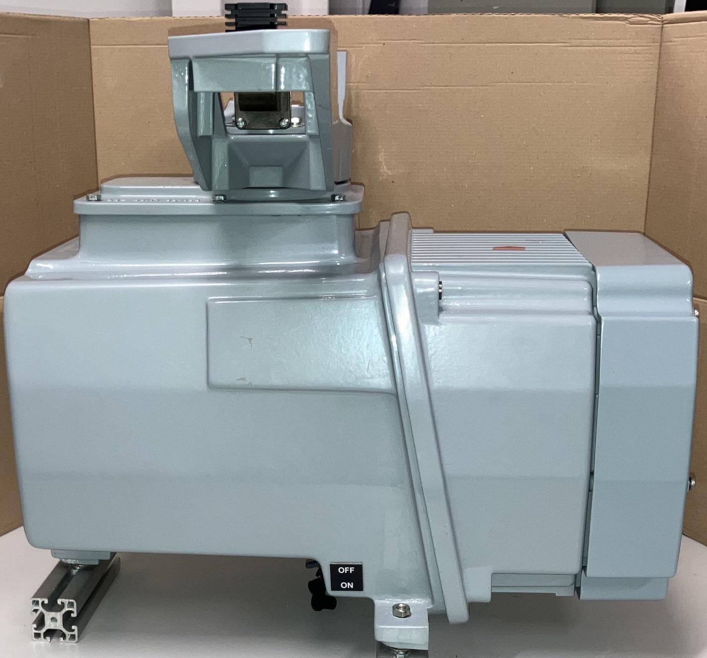
CICPCV-A1
Sep 30, 2024Mk5 Sharp Eye Radar
Equipment Class
MRD - Marine Radar
CICDTX-A613-SF
Aug 25, 2020SHARPEYE RADAR TRANSCEIVER
Equipment Class
TNB - Licensed Non-Broadcast Station Transmitter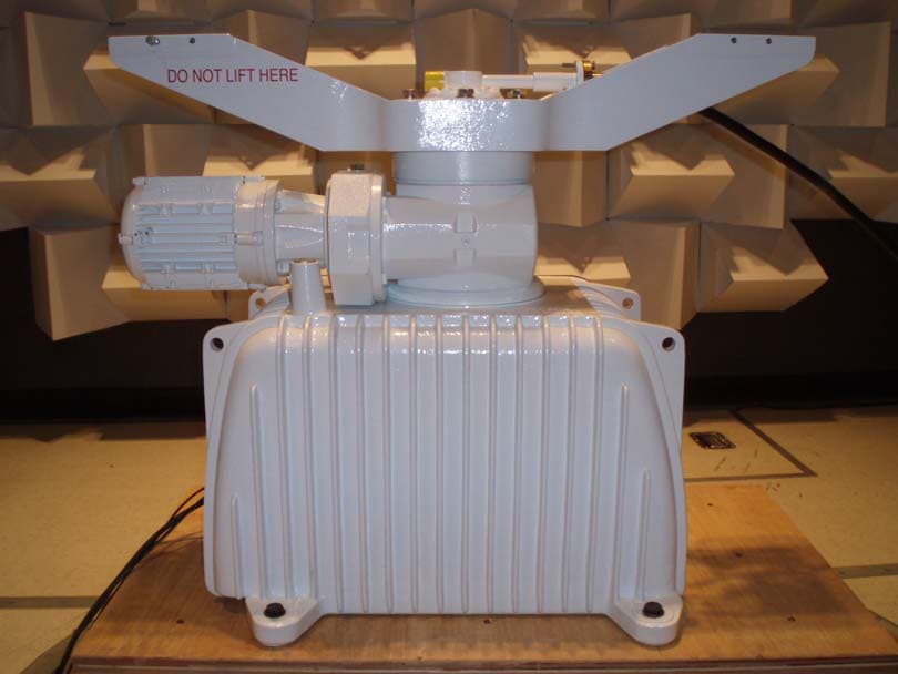
CICDTX-A3-FDLR
May 19, 2015X BAND RADAR
Equipment Class
MRD - Marine Radar
CICDTX-A3
May 09, 2011RADAR
Equipment Class
MRD - Marine Radar
CICCTX-A9
Mar 28, 2002'S' Band Radar
Equipment Class
MRD - Marine Radar