CJ6DCE44941ATri-Mode Dual Band Analog/PCS Mobile Phone
Dynabook Inc.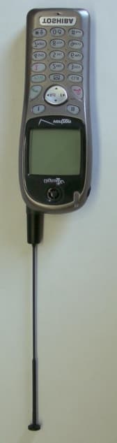
Click to zoom
Application Details
- Equipment Class
- PCE - PCS Licensed Transmitter held to ear
- Date of Grant
- Mar 18, 2002
- Application Purpose
- Original Equipment
- Date of Application
- Sep 30, 2001
- Equipment Note
- Tri-Mode Dual Band Analog/PCS Mobile Phone
- Frequency Range
- 824.04000000 - 848.97000000
- Company
- Dynabook Inc.
- Country
- Japan
Documents & Files
Document Text
Text extracted from the exhibit documents filed with the FCC. Open a document above to read the original.
Users Manual
APPLICANT: TOSHIBA CORPORATIONTRANSCEIVER TYPE: CJ6DCE44941A PAGE 1 OF EXHIBIT T ype“User Manual” OPERATING INSTRUCTIONS TABLE OF CONTENTS PAGE 1. FUNCTIONS 1-1 External View of the Unit 2 1-2 Function of Keys and Controls3 1-3 LCD Readout Indication Items4 2. OPERATION 2-1 Basic Operation5 2-2 Placing Telephone Calls6 2-3 End to End Signaling6 2-4 Call Time Display6 3. INPORTANT SAFETY INFORMATION7 4. WARNING7 5. FCC RF EXPOSURE INFORMATION8 APPLICANT: TOSHIBA CORPORATIONTRANSCEIVER TYPE: CJ6DCE44941A PAGE 2 OF EXHIBIT T ype“User Manual” 1.FUNCTIONS 1-1 EXTERNAL VIEW OF THE UNIT Retractable Whip Antenna Incoming Call & Charging Indicator End Key with Power On/Off Multi Function Key • Up-arrow • Recall • Function • Down-arrow Microphone Soft Key1 Message Access Key • Power Indicator • Receiving Signal Strength Indicator • Digital Mode Indicator • IN USE Indicator • Roaming Indicator • Message Indicator • Vibrating Indicator • Battery Level Indicator Digit Keys 64x129 Dot Display Data Connector DC Socket Send Key Earpiece Earphone Mic Jack Clear Key Voice Mail Dial Key Soft Key2 APPLICANT: TOSHIBA CORPORATIONTRANSCEIVER TYPE: CJ6DCE44941A PAGE 3 OF EXHIBIT T ype“User Manual” 2-2 FUNCTION OF KEYS AND CONTROLS Digit Keys To enter a Telephone Numbers, Names or special characters. is also used for One- Touch Emergency feature. To originate or receive a Call. To terminate a Call and to turn the Unit ON/OFF. To recall phone numbers from memory. To be used with other Keys to activate several special features. To control Earpiece audio level, Alert Tone and key Tone. Also used as Up/Down-arrow keys To dial most frequently called Number from specially assigned Memory Address only by One Key stroke. To readout Text Massage or Voice Mail Notification from me mo ry . To clear the Digit from memory and Display. Soft key 1 Key-Board Arrangement Function Keys Soft key 2 APPLICANT: TOSHIBA CORPORATIONTRANSCEIVER TYPE: CJ6DCE44941A PAGE 4 OF EXHIBIT T ype“User Manual” 2-3 LCD READOUT INDICATION ITEMS ItemDescription Receiving Signal Strength Indicator. The number of lines indicates the received Signal Strength, and is also used as a POWER ON Indicator. Digital Mode Indicator. To indicate the phone is operating in digital mode. A Call is in process. No Service Indicator. The phone cannot receive signals. The phone is out of the Home-Area. Message indicator. To indicate that new Text Message are stored in memory or new Voice Messages are in your Voice Mailbox. Vibrator Alert Indicator Battery Level Indicator. Monitor the current battery voltage level. Graphic full-dot matrix display with flexible font size in 3 to 7 line. APPLICANT: TOSHIBA CORPORATIONTRANSCEIVER TYPE: CJ6DCE44941A PAGE 5 OF EXHIBIT T ype“User Manual” 3. OPERATION 3-1 BASIC OPERATION Turning the Unit On Press the switch. The indicator will light (all indicators will light momentarily and then shows your Telephone Number, and a Tone will be heard). Note: To turn the Unit OFF, press again for about one second. * Signal Strength Indicator This enables you to know the Signal Strength in your Area. The number of the shaded blocks indicates it, and four blocks is the maximum level. The display will vary as your car moves. If the signal is not strong enough to originate a call, “No Service” will appear on the Dot display and also “No Service Indicator” will lit on. To Store a Number in Memory 1. Press then enter a Telephone Number. 2. Press ,, then enter the Memory Address (01 through 99). To Recall a Number from Memory Press , the display shows “Address” then enter the Memory Address (01 through 99). Phone Book Scroll This feature will be useful in finding a certain Telephone Number by scrolling the Repertory Memory Addresses 1. Press , enter the memory address (01 through 99) 2. Press or : Previous Address : Next Address Automatic Number Entry This feature allows an automatic Number Entry into the vacant Repertory Memory Address. 1. Enter a Telephone Number. 2. Press ,,,. If there is no vacant Address in the assigned Area, Telephone Number will remain not entered in the Memory. To Lock the Unit Press ,,. The Unit will remain locked until unlocked, even if the power is turned off. To Unlock the Unit Enter the 4 digit unlock Code. The “LOCK” will go out when the Unit is unlocked. APPLICANT: TOSHIBA CORPORATIONTRANSCEIVER TYPE: CJ6DCE44941A PAGE 6 OF EXHIBIT T ype“User Manual” Volume Control An Audio Level of the Alert Tone, Earpiese and the Key Tone can be adjusted by the Volume Control Buttons. Earpiece: Keep pressing or Button until the moderate Sound Level is got. Alert Tone Level will be displayed on the Readout digitally during the level adjustment and the Sample Tone will help you to know the Sound Level when not engaged in a Telephone Conversation. 3-2 PLACING TELEPHONE CALLS To Place a Call 1. Enter a Telephone Number. Maximumits of the dialed number are displayed on the digital Readout. 2. If a dialing error is made, press then enter the telephone number again. By pressing momentarily (less than approx. 0.5 sec.), only last digit can be cleared. (Last Digit clear) 3. Press . The indicator will light. If a Call Fails to go Through If you hear the Reorder signal, press and try again. Redial: If the Intercept signal is heard, press and dial the Correct Number. To Terminate a Call Press . The indicator will go out. To Receive Calls W hen the Telephone rings, press to answer. The indicator will light. To Place a Call to a Number in Memory Pressing , then enter the Memory Address (01 through 99). If you want to see all number, press , 1. Press . The indicator will light, and the Call will be placed. 3-3 END TO END SIGNALLING This feature permits you to utilize some attractive ways of phone, such as Accessing Discounted Long Distance Network, Signal Pager, or Banking by Phone etc. For these purposes, the signaling should be in DTMF. ( Touch Tone TM ) 3-4 CALL TIME DISPLAY This Feature automatically counts the Time while the Conversation is being…
Text truncated - open the document above for the full version.
Cover Letter(s)
APPLICANT: TOSHIBA CORPORATIONTRANSCEVER TYPE: CJ6DCE44941A PAGE 1 OF EXHIBIT T ype“Cover Letters” LIST OF EXHIBITS EXHIBIT Type.DESCRIPTION Attestation Statement(4 Pages) Request for confidentiality (1 Pages) Block Diagram of Handheld Portable Telephone Transceiver(1 Pages) Cover Letters (List of Exhibit)(1 Pages) External Photos(2 Pages) ID Label / Location Information(3 Pages) Internal Photos(10Pages) Operational Description(13 Pages) Parts List / Tune Up Information(21 Pages) Schematic Diagram of Transceiver RF/BB(3 Pages) Test Report (Include Exhibit type RF Exposure Information)(215 Pages) Test Set Up(4 Pages) User Manual(9 Pages)
External Photos
APPLICANT: TOSHIBA CORPORATIONTRANSCEIVER TYPE:CJ6DCE44941A PAGE 1 OF EXHIBIT T ype“External Photos” Handheld Portable General Appearance APPLICANT: TOSHIBA CORPORATIONTRANSCEIVER TYPE:CJ6DCE44941A PAGE 2 OF EXHIBIT T ype“External Photos” Handheld Portable Inside View (Showing FCC ID Nameplate)
ID Label/Location Info
APPLICANT: TOSHIBA CORPORATIONTRANSCEIVER TYPE: CJ6DCE44941A PAGE 1 OF EXIBIT Type“ID Label/Location Information” Subsection 2.1033 (c)(1). Manufacturer Address TOSHIBA Corporation1-1,Sihbaura 1-Chome, Minato-ku, Tokyo, 105-8001 Japan Toshiba America Information System Inc.9740 Irvine Boulevard, Irvine, California 92618-1697 U.S.A. Nanjing Postel Wong ZHISuning Universal Mansiong, Room 1898 Telecommunications co.,ltd188 Guanzhou Road Nanjing, China 210024 W elco China Limited Man Fung Industrial Estate, Shajing, Po On, Shenzhen, Guang Dong Province Peoples Republic of China MANUFACTURING LOCATION The equipment which is the subject of this Application will initially be manufactured by Toshiba Corporation, Hino Works, Asahigaoka 3-1-1 Hino-shi, Tokyo 191-8555, Japan. Middle in 2002, Toshiba Corporation plans to transfer a part of the manufacturing process for this product to the United States, at Irvine Works of Toshiba America Information Systems, Inc., 9740 Irvine Boulevard, Irvine, California 92618-1697. When units are completed by Toshiba America Information Systems Inc. at Irvine Works, the design and initial manufacturing of the product, or least its major components, will still be done at Hino W orks in Japan. Final Assembly and Testing will be done at Irvine W orks. It has not yet been finally decided how much of the manufacturing process will be done at Irvine W orks, nor has it been decided how many units will be completed at Hino W orks and how many at Irvine W orks. Those numbers will vary from time to time depending on market demand for the product and available plant capacity at each location. Toshiba America Information Systems, Inc. is a wholly owned subsidiary of Toshiba Corporation. The procedures at Irvine W orks will be similar to those at Hino W orks and will be designed and supervised by Hino technical personnel. The end product will be identical in design, performance, and quality, regardless of where final assembly takes place, and will not be distinguishable by the user based on the local of final assembly. In addition to above, middle in 2002, Toshiba corporation plans to transfer the manufacturing process for this product to China, at Nanjing Postel Wong ZHI Telecommunications co.,ltd. Suning Universal Mansiong, Room 1898 188 Guanzhou Road Nanjing, China 210024. Although, the units are completed by Nanjing Postel W ong ZHI Telecommunications co.,ltd., the design and initial manufacturing of the product has been done at Hino W orks in Japan as above mentioned. And although units are completed by Nanjing Postel W ong ZHI Telecommunications co.,ltd in China, most components will still be supplied from Hino W orks in Japan. In addition to above, middle in 2002, Toshiba corporation plans to transfer the manufacturing process for this product to China, at Welco China Limited a member of Wong ' s International (Holding’s) Ltd. in Hong APPLICANT: TOSHIBA CORPORATIONTRANSCEIVER TYPE: CJ6DCE44941A PAGE 2 OF EXIBIT Type“ID Label/Location Information” Kong. Man Fung Industrial Estate, Shajing, Po On, Shenzen, Guang Dong province, People's Republic of China. Even though, the units are completed by W elco China Limited in China, the design and initial manufacturing of the product has been done at Hino W orks in Japan as above mentioned. And although units are completed by W elco China Limited in China, most components will still be supplied from Hino Works in Japan. The procedures at Irvine W orks, Nanjing Postel W ong ZHI Telecommunications co.,ltd and W elco China Limited will be similar to those at Hino works and will be designed and supervised by Hino technical personnel. The end product will be identical in design, performance, and quality, regardless of where final assembly takes place, and will not be distinguishable by the user based on the local of final assembly. The FCC Identifier will be the same regardless of the location where a unit of the product is finally assembled, at Hino Works, Irvine Works or Welco China Limited. The final assembly point of any one unit may be determined by the Serial Number. The Number Assignment Rule is as follows. M M Y Z Z Z Z Z Z Z Z Serial Number Last Digit of the Year Month in which the Unit is manufactured
ID Label/Location Info
APPLICANT: TOSHIBA CORPORATIONTRANSCEIVER TYPE: CJ6DCE44941A PAGE 3 OF EXIBIT Type“ID Label/Location Information” Subsection Subsection 2.1033 (c) (2) FCC ID: CJ6DCE44941A Unit: mm FCC ID Nameplate A Nameplate of this type or one similar to this will be affixed to every Transceiver. It will be placed on the outside of the Handheld Portable Telephone as shown in the EXHIBIT Type “External Photo”. For Units for which manufacture or final assembly is performed in the United States, the words MADE IN JAPAN may remain or may be changed to ASSEMBLED IN USA FROM JAPANESE COMPONENTS or a similar expression depending upon how much of the process is done in the United States and an analysis of the requirements of U.S. Customs Law under those circumstances. For Units for which manufacture or final assembly is performed in China, the words MADE IN JAPAN will be changed to MADE IN CHINA or ASSEMBLED IN CHINA. 16 47
Internal Photos
APPLICANT: TOSHIBA CORPORATIONTRANSCEIVER TYPE:CJ6DCE44941A PAGE 1 OF EXHIBIT T ype“Internal Photos” Handheld Portable MAIN Board (W ith Shield Case and Cover) APPLICANT: TOSHIBA CORPORATIONTRANSCEIVER TYPE:CJ6DCE44941A PAGE 2 OF EXHIBIT T ype“Internal Photos” Handheld Portable MAIN Board (Front side , W ith Shield Cover Removed) APPLICANT: TOSHIBA CORPORATIONTRANSCEIVER TYPE:CJ6DCE44941A PAGE 3 OF EXHIBIT T ype“Internal Photos” Handheld Portable MAIN Board (Front side , W ith Shield Cover and LCD holder Removed) APPLICANT: TOSHIBA CORPORATIONTRANSCEIVER TYPE:CJ6DCE44941A PAGE 4 OF EXHIBIT T ype“Internal Photos” Handheld Portable MAIN Board (Back side , W ith shield cover)
Internal Photos
APPLICANT: TOSHIBA CORPORATIONTRANSCEIVER TYPE: CJ6DCE44941A PAGE 3 OF EXIBIT Type“ID Label/Location Information” Subsection Subsection 2.1033 (c) (2) FCC ID: CJ6DCE44941A Unit: mm FCC ID Nameplate A Nameplate of this type or one similar to this will be affixed to every Transceiver. It will be placed on the outside of the Handheld Portable Telephone as shown in the EXHIBIT Type “External Photo”. For Units for which manufacture or final assembly is performed in the United States, the words MADE IN JAPAN may remain or may be changed to ASSEMBLED IN USA FROM JAPANESE COMPONENTS or a similar expression depending upon how much of the process is done in the United States and an analysis of the requirements of U.S. Customs Law under those circumstances. For Units for which manufacture or final assembly is performed in China, the words MADE IN JAPAN will be changed to MADE IN CHINA or ASSEMBLED IN CHINA. 16 47
Internal Photos
APPLICANT: TOSHIBA CORPORATIONTRANSCEIVER TYPE:CJ6DCE44941A PAGE 9 OF E XH IB IT T ype“Internal Photos” Handheld Portable Key Board (Front side ) Handheld Portable Key Board (Back side) APPLICANT: TOSHIBA CORPORATIONTRANSCEIVER TYPE:CJ6DCE44941A PAGE 10 OF EXHIBIT Type“Internal Photos” Handheld Portable Inner Case (Front side) Handheld Portable Inner Case (Back side)
Internal Photos
APPLICANT: TOSHIBA CORPORATION•••••••••••••••TRANSCEIVER TYPE:CJ6DCE44941A PAGE 11 OF EXHIBIT Type “Internal Photos” Handheld Portable MAIN Board (Front side, With shielding removed.) APPLICANT: TOSHIBA CORPORATION•••••••••••••••TRANSCEIVER TYPE:CJ6DCE44941A PAGE 12 OF EXHIBIT Type “Internal Photos” (Back side, With shielding removed.)
RF Exposure Info
© 2001 PCTEST Lab FCC ID: CJ6DCE44941A (CDM-9150) NVLAP Lab Code: 100431-0 TOSHIBA Tri-Mode Dual-Band Analog/PCS Phone © 2001 PCTEST Lab FCC ID: CJ6DCE44941A (CDM-9150) NVLAP Lab Code: 100431-0 TOSHIBA Tri-Mode Dual-Band Analog/PCS Phone © 2001 PCTEST Lab FCC ID: CJ6DCE44941A (CDM-9150) NVLAP Lab Code: 100431-0 TOSHIBA Tri-Mode Dual-Band Analog/PCS Phone © 2001 PCTEST Lab FCC ID: CJ6DCE44941A (CDM-9150) NVLAP Lab Code: 100431-0 TOSHIBA Tri-Mode Dual-Band Analog/PCS Phone © 2001 PCTEST Lab FCC ID: CJ6DCE44941A (CDM-9150) NVLAP Lab Code: 100431-0 TOSHIBA Tri-Mode Dual-Band Analog/PCS Phone © 2001 PCTEST Lab FCC ID: CJ6DCE44941A (CDM-9150) NVLAP Lab Code: 100431-0 TOSHIBA Tri-Mode Dual-Band Analog/PCS Phone
RF Exposure Info
© 2001 PCTEST Lab FCC ID: CJ6DCE44941A (CDM-9150) NVLAP Lab Code: 100431-0 TOSHIBA Tri-Mode Dual-Band Analog/PCS Phone © 2001 PCTEST Lab FCC ID: CJ6DCE44941A (CDM-9150) NVLAP Lab Code: 100431-0 TOSHIBA Tri-Mode Dual-Band Analog/PCS Phone © 2001 PCTEST Lab FCC ID: CJ6DCE44941A (CDM-9150) NVLAP Lab Code: 100431-0 TOSHIBA Tri-Mode Dual-Band Analog/PCS Phone
RF Exposure Info
© 2001 PCTEST Lab FCC ID: CJ6DCE44941A (CDM-9150) NVLAP Lab Code: 100431-0 TOSHIBA Tri-Mode Dual-Band Analog/PCS Phone © 2001 PCTEST Lab FCC ID: CJ6DCE44941A (CDM-9150) NVLAP Lab Code: 100431-0 TOSHIBA Tri-Mode Dual-Band Analog/PCS Phone © 2001 PCTEST Lab FCC ID: CJ6DCE44941A (CDM-9150) NVLAP Lab Code: 100431-0 TOSHIBA Tri-Mode Dual-Band Analog/PCS Phone
RF Exposure Info
© 2001 PCTEST Lab FCC ID: CJ6DCE44941A (CDM-9150) NVLAP Lab Code: 100431-0 TOSHIBA Tri-Mode Dual-Band Analog/PCS Phone © 2001 PCTEST Lab FCC ID: CJ6DCE44941A (CDM-9150) NVLAP Lab Code: 100431-0 TOSHIBA Tri-Mode Dual-Band Analog/PCS Phone © 2001 PCTEST Lab FCC ID: CJ6DCE44941A (CDM-9150) NVLAP Lab Code: 100431-0 TOSHIBA Tri-Mode Dual-Band Analog/PCS Phone
RF Exposure Info
© 2001 PCTEST Lab FCC ID: CJ6DCE44941A (CDM-9150) NVLAP Lab Code: 100431-0 TOSHIBA Tri-Mode Dual-Band Analog/PCS Phone © 2001 PCTEST Lab FCC ID: CJ6DCE44941A (CDM-9150) NVLAP Lab Code: 100431-0 TOSHIBA Tri-Mode Dual-Band Analog/PCS Phone © 2001 PCTEST Lab FCC ID: CJ6DCE44941A (CDM-9150) NVLAP Lab Code: 100431-0 TOSHIBA Tri-Mode Dual-Band Analog/PCS Phone © 2001 PCTEST Lab FCC ID: CJ6DCE44941A (CDM-9150) NVLAP Lab Code: 100431-0 TOSHIBA Tri-Mode Dual-Band Analog/PCS Phone
RF Exposure Info
Peak SAR Location © 2001 PCTEST Lab TOSHIBA FCC ID: CJ6DCE44941A (Model: CDM-9150) NVLAP Lab Code: 100431-0 Tri-Mode Dual-Band Analog/PCS Phone (AMPS/CDMA) 800 MHz Head SAR File : c:/idx3/SYSTEM/SARMEAS3/data/Normal/01090536_ZOOM.VLT Start : 5-Sep-101 06:46:31 pm End : 5-Sep-101 06:54:37 pm Radio Type : TOSHIBA Model Number : CDM-9150 Serial Number : 5 Frequency : 824.04 MHz Peak Trans. Pwr : 0.530 W Start Trans. Pwr: 0.530 W Antenna Type : Helical Antenna Posn. : In Phantom Type : Head Phantom Posn. : Right Ear Scan Type : ZOOM/SAR Probe Name : PCTEST Field Type : E Field Orientation : 0 Degrees Mixture Type = Brain Mixture Dielectric Constant = 41.500 Mixture Conductivity = 0.900 Comment : TOSHIBA TRI-MODE PHONE - AMPS MODE CH 0991 Conducted 27.2 dBm TOSHIBA TRI-MODE PHONE Robot : PCTEST Probe Offset = 0.25 cm Sensor Factor = 0.0108 Conversion Factor = 0.788 PCTEST Amplifier Channel Settings : 0.166 0.135 0.132 Max Location : X = -2.250, Y = 0.000, Z = 0.000 (cm) Value = 17.787 Measured Values (volts) = 1.711E-002 1.429E-002 1.173E-002 9.921E-003 8.524E-003 7.409E-003 6.494E-003 5.972E-003 5.456E-003 5.133E-003 4.799E-003 4.529E-003 4.116E-003 3.617E-003 3.224E-003 2.717E-003 2.566E-003 2.196E-003 2.141E-003 2.229E-003 2.361E-003 Calc. Voltage @ Surface (Vs) = 0.0207 Voltage @ 1.00 cm (Vt) = 0.0099 Ave. Voltage (Vs+Vt)/2 = 0.0153 Ave. SAR over 1 g (mW/g) = 1.1162 File : c:/idx3/SYSTEM/SARMEAS3/data/Normal/01090549_ZOOM.VLT Start : 5-Sep-101 08:43:08 pm End : 5-Sep-101 08:43:59 pm Radio Type : TOSHIBA Model Number : CDM-9150 Serial Number : 5 Frequency : 824.04 MHz Peak Trans. Pwr : 0.530 W Start Trans. Pwr: 0.530 W Antenna Type : Helical Antenna Posn. : Out Phantom Type : Head Phantom Posn. : Right Ear Scan Type : SAR Probe Name : PCTEST Field Type : E Field Orientation : 0 Degrees Mixture Type = Brain Mixture Dielectric Constant = 41.500 Mixture Conductivity = 0.900 Comment : TOSHIBA TRI-MODE PHONE - FM MODE CH 0991 Conducted 27.2 dBm TOSHIBA TRI-MODE PHONE Robot : PCTEST Probe Offset = 0.25 cm Sensor Factor = 0.0108 Conversion Factor = 0.788 PCTEST Amplifier Channel Settings : 0.166 0.135 0.132 Max Location : X = -2.250, Y = -0.250, Z = 0.000 (cm) Value = 21.030 Measured Values (volts) = 2.285E-002 2.053E-002 1.627E-002 1.368E-002 1.139E-002 9.561E-003 8.036E-003 7.082E-003 6.375E-003 5.854E-003 5.398E-003 5.064E-003 4.576E-003 3.994E-003 3.330E-003 2.576E-003 1.890E-003 1.423E-003 1.237E-003 1.262E-003 1.452E-003 Calc. Voltage @ Surface (Vs) = 0.0271 Voltage @ 1.00 cm (Vt) = 0.0137 Ave. Voltage (Vs+Vt)/2 = 0.0204 Ave. SAR over 1 g (mW/g) = 1.4887 0.0 0.2 0.4 0.6 0.8 1.0 1.2 1.4 1.6 1.8 2.0 mW/g -1012345 Z centimeters SAR Scan File : 01090549_ZOOM Start : 5-Sep-101 08:43:08 pm End : 5-Sep-101 08:43:59 pm TOSHIBA/CDM-9150/5;824.04MHz;W;Helical/Out; Head/Right Ear;SAR;PCTEST/E Field/0 DegreesBrain/41.500/0.900 File : 01090548_ZOOM Start : 5-Sep-101 08:30:35 pm End : 5-Sep-101 08:39:27 pm TOSHIBA/CDM-9150/5;824.04MHz;W;Helical/Out; Head/Right Ear;ZOOM/SAR;PCTEST/E Field/0 DegreesBrain/41.500/0.900 1.534 1.439 1.344 1.249 1.154 1.059 0.964 0.869 0.774 0.678 File : 01090548_ZOOM Start : 5-Sep-101 08:30:35 pm End : 5-Sep-101 08:39:27 pm TOSHIBA/CDM-9150/5;824.04MHz;W;Helical/Out; Head/Right Ear;ZOOM/SAR;PCTEST/E Field/0 DegreesBrain/41.500/0.900 1.534 1.439 1.344 1.249 1.154 1.059 0.964 0.869 0.774 0.678 File : c:/idx3/SYSTEM/SARMEAS3/data/Normal/01090541_ZOOM.VLT Start : 5-Sep-101 07:28:29 pm End : 5-Sep-101 07:37:23 pm Radio Type : TOSHIBA Model Number : CDM-9150 Serial Number : 5 Frequency : 836.49 MHz Peak Trans. Pwr : 0.530 W Start Trans. Pwr: 0.530 W Antenna Type : Helical Antenna Posn. : In Phantom Type : Head Phantom Posn. : Right Ear Scan Type : ZOOM/SAR Probe Name : PCTEST Field Type : E Field Orientation : 0 Degrees Mixture Type = Brain Mixture Dielectric Constant = 41.500 Mixture Conductivity = 0.900 Comment : TOSHIBA TRI-MODE PHONE - AMPS MODE CH 0383 Conducted 27.2 dBm TOSHIBA TRI-MODE PHONE Robot : PCTEST Probe Offset = 0.25 cm Sensor Factor = 0.0108 Conversion Factor = 0.788 PCTEST Amplifier Channel Settings : 0.166 0.135 0.132 Max Location : X = -2.250, Y = -0.250, Z = 0.000 (cm) Value = 22.667 Measured Values (volts) = 2.245E-002 1.906E-002 1.545E-002 1.293E-002 1.093E-002 9.279E-003 7.887E-003 6.948E-003 6.271E-003 5.741E-003 5.310E-003 4.832E-003 4.291E-003 3.767E-003 3.001E-003 2.347E-003 1.824E-003 1.470E-003 1.378E-003 1.441E-003 1.652E-003 Calc. Voltage @ Surface (Vs) = 0.0271 Voltage @ 1.00 cm (Vt) = 0.0129 Ave. Voltage (Vs+Vt)/2 = 0.0200 Ave. SAR over 1 g (mW/g) = 1.4593 File : c:/idx3/SYSTEM/SARMEAS3/data/Normal/01090543_ZOOM.VLT Start : 5-Sep-101 07:38:50 pm End : 5-Sep-101 07:47:41 pm Radio Type : TOSHIBA Model Number : CDM-9150 Serial Number : 5 Frequency : 836.49 MHz Peak Trans. Pwr : 0.530 W Start Trans. Pwr: 0.530 W Antenna Type : Helical Antenna Posn. : Out Phantom Type : Head Phantom Posn. : Right Ear Scan Type : ZOOM/SAR Probe Name : PCTEST Field Type : E Field Orientation : 0 Degrees Mixture Type = Brain Mixture Dielectric Constant = 41.500 Mixture Conductivity = 0.900 Comment : TOSHIBA TRI-MODE PHONE - AMPS MODE CH 0383 Conducted 27.2 dBm TOSHIBA TRI-MODE PHONE Robot : PCTEST Probe Offset = 0.25 cm Sensor Factor = 0.0108 Conversion Factor = 0.788 PCTEST Amplifier Channel Settings : 0.166 0.135 0.132 Max Location : X = -2.250, Y = -0.250, Z = 0.000 (cm) Value = 20.801 Measured Values (volts) = 2.030E-002 1.766E-002 1.444E-002 1.205E-002 1.014E-002 8.425E-003 7.154E-003 6.252E-003 5.623E-003 5.195E-003 4.879E-003 4.568E-003 4.231E-003 3.739E-003 3.096E-003 2.458E-003 1.946E-003 1.498E-003 1.352E-003 1.343E-003 1.497E-003 Calc. Voltage @ Surface (Vs) = 0.0241 Voltage @ 1.00 cm (Vt) = 0.0121 Ave. Voltage (Vs+Vt)/2 = 0.0181 Ave. SAR over 1 g (mW/g) = 1.3186 File : c:/idx3/SYSTEM/SARMEAS3/data/Normal/01090544_ZOOM.VLT Start : 5-Sep-101 07:49:54 pm End : 5-Sep-101 07:58:45 pm Radio Type : TOSHIBA Model Number : CDM-9150 Serial Number : 5 Frequency : 848.97 MH…
Text truncated - open the document above for the full version.
RF Exposure Info
Leather Carrying Case Leather Carrying Case and Belt Clip Belt Clip
RF Exposure Info
© 2001 PCTEST Lab TOSHIBA FCC ID: CJ6DCE44941A (Model: CDM-9150) NVLAP Lab Code: 100431-0 Tri-Mode Dual-Band Analog/PCS Phone (AMPS/CDMA) © 2001 PCTEST Lab TOSHIBA FCC ID: CJ6DCE44941A (Model: CDM-9150) NVLAP Lab Code: 100431-0 Tri-Mode Dual-Band Analog/PCS Phone (AMPS/CDMA) © 2001 PCTEST Lab TOSHIBA FCC ID: CJ6DCE44941A (Model: CDM-9150) NVLAP Lab Code: 100431-0 Tri-Mode Dual-Band Analog/PCS Phone (AMPS/CDMA) © 2001 PCTEST Lab TOSHIBA FCC ID: CJ6DCE44941A (Model: CDM-9150) NVLAP Lab Code: 100431-0 Tri-Mode Dual-Band Analog/PCS Phone (AMPS/CDMA) © 2001 PCTEST Lab TOSHIBA FCC ID: CJ6DCE44941A (Model: CDM-9150) NVLAP Lab Code: 100431-0 Tri-Mode Dual-Band Analog/PCS Phone (AMPS/CDMA) © 2001 PCTEST Lab TOSHIBA FCC ID: CJ6DCE44941A (Model: CDM-9150) NVLAP Lab Code: 100431-0 Tri-Mode Dual-Band Analog/PCS Phone (AMPS/CDMA) © 2001 PCTEST Lab TOSHIBA FCC ID: CJ6DCE44941A (Model: CDM-9150) NVLAP Lab Code: 100431-0 Tri-Mode Dual-Band Analog/PCS Phone (AMPS/CDMA)
RF Exposure Info
File : c:/idx3/SYSTEM/SARMEAS3/data/Normal/01111932_ZOOM.VLT Start : 19-Nov-101 07:57:02 pm End : 19-Nov-101 08:03:05 pm Radio Type : TOSHIBA Model Number : CDM-9150 Serial Number : 5 Frequency : 824.04 MHz Peak Trans. Pwr : 0.530 W Start Trans. Pwr: 0.530 W Antenna Type : Helical Antenna Posn. : Out Phantom Type : Head Phantom Posn. : Right Ear Scan Type : ZOOM/SAR Probe Name : PCTEST Field Type : E Field Orientation : 0 Degrees Mixture Type = Brain Mixture Dielectric Constant = 41.500 Mixture Conductivity = 0.900 Comment : TOSHIBA TRI-MODE PHONE - AMPS MODE CH 0991 Conducted 27.2 dBm TOSHIBA TRI-MODE PHONE Robot : PCTEST Probe Offset = 0.20 cm Sensor Factor = 0.0108 Conversion Factor = 0.325 PCTEST Amplifier Channel Settings : 0.239 0.278 0.294 Max Location : X = -4.000, Y = -1.000, Z = 0.000 (cm) Value = 50.112 Measured Values (volts) = 4.652E-002 3.523E-002 3.182E-002 2.914E-002 2.701E-002 2.516E-002 2.362E-002 2.224E-002 2.081E-002 1.934E-002 1.806E-002 1.714E-002 1.589E-002 1.465E-002 1.370E-002 1.310E-002 1.274E-002 1.202E-002 1.183E-002 1.136E-002 1.096E-002 Calc. Voltage @ Surface (Vs) = 0.0543 Voltage @ 1.00 cm (Vt) = 0.0287 Ave. Voltage (Vs+Vt)/2 = 0.0415 Ave. SAR over 1 g (mW/g) = 1.2494 0.2 0.4 0.6 0.8 1.0 1.2 1.4 1.6 1.8 mW/g -1012345 Z centimeters SAR Scan File : 01111932_ZOOM Start : 19-Nov-101 07:57:02 pm End : 19-Nov-101 08:03:05 pm TOSHIBA/CDM-9150/5;824.04MHz;W;Helical/Out; Head/Right Ear;ZOOM/SAR;PCTEST/E Field/0 DegreesBrain/41.500/0.900 File : 01111932_ZOOM Start : 19-Nov-101 07:57:02 pm End : 19-Nov-101 08:03:05 pm TOSHIBA/CDM-9150/5;824.04MHz;W;Helical/Out; Head/Right Ear;ZOOM/SAR;PCTEST/E Field/0 DegreesBrain/41.500/0.900 1.51 1.40 1.28 1.17 1.06 0.95 0.84 0.73 0.62 0.50 File : 01111932_ZOOM Start : 19-Nov-101 07:57:02 pm End : 19-Nov-101 08:03:05 pm TOSHIBA/CDM-9150/5;824.04MHz;W;Helical/Out; Head/Right Ear;ZOOM/SAR;PCTEST/E Field/0 DegreesBrain/41.500/0.900 1.51 1.40 1.28 1.17 1.06 0.95 0.84 0.73 0.62 0.50 File : c:/idx3/SYSTEM/SARMEAS3/data/Normal/01111933_ZOOM.VLT Start : 19-Nov-101 08:03:32 pm End : 19-Nov-101 08:04:21 pm Radio Type : TOSHIBA Model Number : CDM-9150 Serial Number : 5 Frequency : 824.04 MHz Peak Trans. Pwr : 0.530 W Start Trans. Pwr: 0.530 W Antenna Type : Helical Antenna Posn. : Out Phantom Type : Head Phantom Posn. : Right Ear Scan Type : SAR Probe Name : PCTEST Field Type : E Field Orientation : 0 Degrees Mixture Type = Brain Mixture Dielectric Constant = 41.500 Mixture Conductivity = 0.900 Comment : TOSHIBA TRI-MODE PHONE - AMPS MODE CH 0991 Conducted 27.2 dBm TOSHIBA TRI-MODE PHONE Robot : PCTEST Probe Offset = 0.20 cm Sensor Factor = 0.0108 Conversion Factor = 0.325 PCTEST Amplifier Channel Settings : 0.239 0.278 0.294 Max Location : X = -4.000, Y = -1.000, Z = 0.000 (cm) Value = 50.112 Measured Values (volts) = 4.181E-002 2.629E-002 2.041E-002 1.533E-002 1.228E-002 1.055E-002 8.379E-003 8.347E-003 7.318E-003 6.890E-003 8.276E-003 7.444E-003 8.549E-003 6.964E-003 3.406E-003 3.142E-003 Calc. Voltage @ Surface (Vs) = 0.0516 Voltage @ 1.00 cm (Vt) = 0.0294 Ave. Voltage (Vs+Vt)/2 = 0.0405 Ave. SAR over 1 g (mW/g) = 1.2190 0.0 0.2 0.4 0.6 0.8 1.0 1.2 1.4 mW/g -10123456789101112131415 Z centimeters SAR Scan File : 01111933_ZOOM Start : 19-Nov-101 08:03:32 pm End : 19-Nov-101 08:04:21 pm TOSHIBA/CDM-9150/5;824.04MHz;W;Helical/Out; Head/Right Ear;SAR;PCTEST/E Field/0 DegreesBrain/41.500/0.900 File : c:/idx3/SYSTEM/SARMEAS3/data/Normal/01111927_ZOOM.VLT Start : 19-Nov-101 06:49:57 pm End : 19-Nov-101 07:09:08 pm Radio Type : TOSHIBA Model Number : CDM-9150 Serial Number : 5 Frequency : 1908.75 MHz Peak Trans. Pwr : 0.250 W Start Trans. Pwr: 0.250 W Antenna Type : Helical Antenna Posn. : Out Phantom Type : Head Phantom Posn. : Right Ear Scan Type : ZOOM/SAR Probe Name : PCTEST Field Type : E Field Orientation : 0 Degrees Mixture Type = Brain Mixture Dielectric Constant = 40.400 Mixture Conductivity = 1.620 Comment : TOSHIBA TRI-MODE PHONE - PCS MODE CH 1175 Conducted 24.0 dBm TOSHIBA TRI-MODE PHONE Robot : PCTEST Probe Offset = 0.20 cm Sensor Factor = 0.0108 Conversion Factor = 0.550 PCTEST Amplifier Channel Settings : 0.309 0.361 0.421 Max Location : X = 0.500, Y = -1.500, Z = 0.000 (cm) Value = 31.592 Measured Values (volts) = 3.104E-002 2.415E-002 1.878E-002 1.498E-002 1.263E-002 1.064E-002 9.162E-003 8.237E-003 7.466E-003 6.755E-003 6.419E-003 6.767E-003 6.334E-003 5.819E-003 6.035E-003 5.923E-003 5.805E-003 6.001E-003 6.161E-003 6.337E-003 6.034E-003 Calc. Voltage @ Surface (Vs) = 0.0379 Voltage @ 1.00 cm (Vt) = 0.0145 Ave. Voltage (Vs+Vt)/2 = 0.0262 Ave. SAR over 1 g (mW/g) = 1.3355 0.0 0.2 0.4 0.6 0.8 1.0 1.2 1.4 1.6 1.8 2.0 mW/g -1012345 Z centimeters SAR Scan File : 01111927_ZOOM Start : 19-Nov-101 06:49:57 pm End : 19-Nov-101 07:09:08 pm TOSHIBA/CDM-9150/5;1908.75MHz;W;Helical/Out; Head/Right Ear;ZOOM/SAR;PCTEST/E Field/0 DegreesBrain/40.400/1.620 File : 01111927_ZOOM Start : 19-Nov-101 06:49:57 pm End : 19-Nov-101 07:09:08 pm TOSHIBA/CDM-9150/5;1908.75MHz;W;Helical/Out; Head/Right Ear;ZOOM/SAR;PCTEST/E Field/0 DegreesBrain/40.400/1.620 1.61 1.47 1.34 1.20 1.06 0.93 0.79 0.66 0.52 0.38 File : 01111927_ZOOM Start : 19-Nov-101 06:49:57 pm End : 19-Nov-101 07:09:08 pm TOSHIBA/CDM-9150/5;1908.75MHz;W;Helical/Out; Head/Right Ear;ZOOM/SAR;PCTEST/E Field/0 DegreesBrain/40.400/1.620 1.61 1.47 1.34 1.20 1.06 0.93 0.79 0.66 0.52 0.38 File : c:/idx3/SYSTEM/SARMEAS3/data/Normal/01111931_ZOOM.VLT Start : 19-Nov-101 07:54:27 pm End : 19-Nov-101 07:55:16 pm Radio Type : TOSHIBA Model Number : CDM-9150 Serial Number : 5 Frequency : 824.04 MHz Peak Trans. Pwr : 0.530 W Start Trans. Pwr: 0.530 W Antenna Type : Helical Antenna Posn. : Out Phantom Type : Head Phantom Posn. : Right Ear Scan Type : SAR Probe Name : PCTEST Field Type : E Field Orientation : 0 Degrees Mixture Type = Brain Mixture Dielectric Constant = 41.500 Mixture Conductivity = 0.900 Comment : TOSHIBA TRI-MODE PHONE - AMPS MODE CH 0991 Conducted 27.2 dBm TOSHIBA TRI-MODE PHONE Robot : PCTE…
Text truncated - open the document above for the full version.
RF Exposure Info
SAR TEST DATA SUMMARY Ambient TEMPERATURE (°C) 21.0 Relative HUMIDITY (%) 43.4 Atmospheric PRESSURE (kPa) 101.0 Measured Values: Mixture Type: Brain Dielectric Constant: 41.5 Conductivity: 0.90 Liquid Depth: 15.1 cm Closest Distance (between E-Probe & Phone): 1.9 cm Measurement Results (AMPS Head SAR) FREQUENCY Mo…
Text truncated - open the document above for the full version.
Contact Information
Applicant
Ryuichi Kamimura(Senior Manager)
Technical Contact
Toshiba America Information SystemsPeter Leone
[email protected](949)587-6473
9740 Irvine Boulevard · Irvine, California · United States
Test Firm
PCTEST Engineering Laboratory, Inc.Randy Ortanez
Technical Specifications
| # | Rule Parts | Frequency Range | Power Output | Emission | Tolerance |
|---|---|---|---|---|---|
| 4 | 22H | 824.04 MHz - 848.97 MHz | 600.00 mW | 40K0F1D | 2.5 ppm |
Other Applications from Dynabook Inc.

CJ6PA5347RT
Oct 20, 2022dynabook Wireless Optical Silent Mouse
Equipment Class
DXX - Part 15 Low Power Communication Device Transmitter
CJ6PYT0XPC
Apr 28, 2021Notebook Computer
Equipment Class
DSS - Part 15 Spread Spectrum Transmitter
CJ6UPA5238WL
Sep 01, 2015dynadock WiAC
Equipment Class
NII - Unlicensed National Information Infrastructure TX
CJ6UPA5144TJ
Aug 07, 2014TransferJet USB Adapter
Equipment Class
JBP - Part 15 Class B Computing Device Peripheral
CJ6UPA5145TJ
Aug 07, 2014TransferJet MicroUSB Adapter
Equipment Class
UWB - Ultra Wideband Transmitter