CJ6DCFC009001Tri-Mode Dual-Band Analog/PCS Phone (AMPS/CDMA)
Dynabook Inc.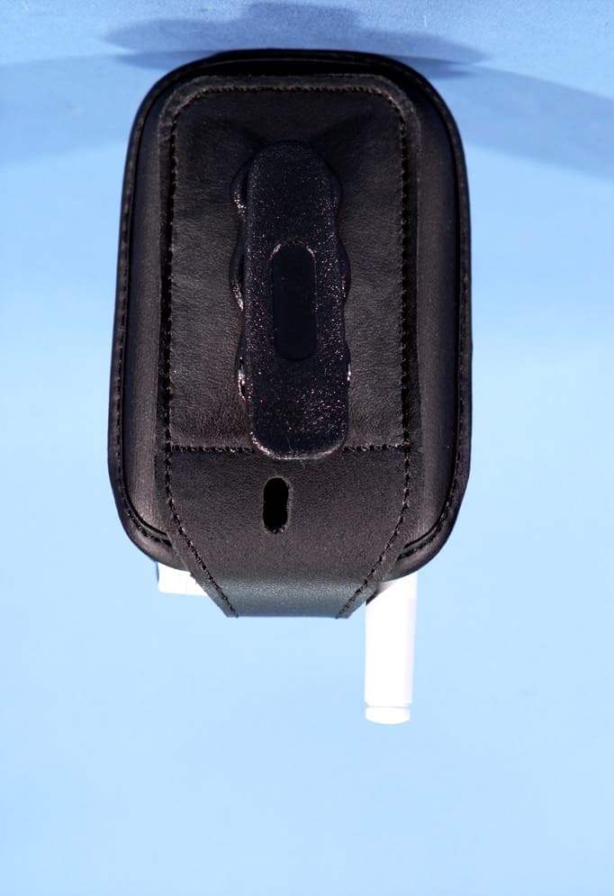
Click to zoom
Application Details
- Equipment Class
- PCE - PCS Licensed Transmitter held to ear
- Date of Grant
- Aug 26, 2003
- Application Purpose
- Original Equipment
- Date of Application
- Aug 26, 2003
- Equipment Note
- Tri-Mode Dual-Band Analog/PCS Phone (AMPS/CDMA)
- Frequency Range
- 1851.25000000 - 1908.75000000
- Company
- Dynabook Inc.
- Country
- Japan
Documents & Files
Document Text
Text extracted from the exhibit documents filed with the FCC. Open a document above to read the original.
Users Manual
Applicant: Toshiba Corporation Transceiver Type: CJ6DCFC009001 - 1 - Exhibit Type “User Manual” CJ6DCFC009001 User Manual Draft July 2003 Table of Contents Your Phone’s Features..................................................................2 Turning Your Phone On and Off.................................................3 Turning Your Phone ON..................................................................3 Turning Your Phone OFF................................................................3 Making and Answering Calls.......................................................4 Making Calls.....................................................................................4 Answering Calls...............................................................................4 Signal Strength.................................................................................4 Body-Worn Operation....................................................................5 Applicant: Toshiba Corporation Transceiver Type: CJ6DCFC009001 - 2 - Exhibit Type “User Manual” Your Phone’s Features 1. LED (green/red) blinks green for incoming calls; blinks red for notifications (messages, voicemail, and alerts). 2. Camera Lens lets you take pictures with auto focus function. 3. Flash helps you take pictures clearly at dark places. 4. Sub Display lets you monitor the phone’s status. 5. Main Display shows the phone’s menus and various features. 6. Left Softkey allows you to select an action or item at the bottom left of the main display. 7. Navigation Key scrolls through menus and displays the next or previous menu option. Also acts as a shortcut key for Web, Find Name in Phone Book, My Menu, and Downloads. 8. TALK allows you to place or to answer a call. 9. Volume Keys adjust the volume during a call or mute the ringer of an incoming call. 10. Side Camera Key activates Camera mode and takes a picture. 11. Speakerphone Key activates Speakerphone mode. 12. MENU accesses the phone’s main menu. 13. Right Softkey allows you to select an action or item at the bottom right of the main display. 14. Headset Jack allows you to plug in an optional headset for hands-free use. 15. END (Power) allows you to power the phone on or off, to end calls, or to return to standby mode from any screen. 16. OK allows you to select highlighted menu items and to confirm actions. 17. Camera/Video Key activates Camera/Video mode and takes a picture. 18. BACK allows you to clear an entry or to back up within a menu. Applicant: Toshiba Corporation Transceiver Type: CJ6DCFC009001 - 3 - Exhibit Type “User Manual” Turning Your Phone On and Off Turning Your Phone ON 1. Fully extend the antenna to receive the best reception. 2. Press [END] for two seconds. (The phone will display “Searching for Service” until it locates a signal, then it will automatically enter standby mode – the phone’s idle state. At this point, you’re ready to begin making and receiving calls.) Turning Your Phone OFF = Press [END] for two seconds until the screen reads “Powering Off.” Applicant: Toshiba Corporation Transceiver Type: CJ6DCFC009001 - 4 - Exhibit Type “User Manual” Making and Answering Calls Making Calls 1. Make sure your phone is on. 2. Enter a phone number. If you make a mistake while dialing, press [BACK] to erase one digit at a time or press and hold [BACK] to erase the entire number. 3. Press [TALK]. 4. When you’re finished, press [END]. Answering Calls 1. Make sure your phone is on. If your phone is off, incoming calls go to your voicemail. 2. When your phone rings or vibrates, answer the call by pressing [TALK]. 3. To end the call, press [END]. Signal Strength You can see the strength of your signal by the signal indicator () on your phone’s display screen. Call quality and signal strength are always best when the antenna is fully raised. If you’re inside a building, being near a window may give you better reception. Applicant: Toshiba Corporation Transceiver Type: CJ6DCFC009001 - 5 - Exhibit Type “User Manual” Body-Worn Operation To maintain compliance with FCC RF exposure guidelines, if you wear a handset on your body, use the Sprint approved carrying case, holster or other accessory. If you do not use a body-worn accessory, ensure the antenna is at least 0.59 inches (1.5 cm) from your body when transmitting. Use of non-Sprint approved accessories may violate FCC RF exposure guidelines. For more information about RF exposure, visit the FCC Web site at www.fcc.gov. Body-worn Operation This device was tested for typical body-worn operations with the BC- 9900 belt-clip and LB-9900 holster models, offered by Audiovox as an accessory to this phone, and found to comply with FCC RF exposure requirements. Third-party belt-clips, holsters and similar accessories should be avoided, as they have not been tested and may not comply with FCC RF exposure limits. For more information about RF exposure, please visit the FCC website at www.fcc.gov .
Cover Letter(s)
August 25, 2003 Federal Communications Commission Equipment Approval Services 7435 Oakland Mills Road Columbia, MD 21046 SUBJECT: TOSHIBA Corporation FCC ID: CJ6DCFC009001 Part 22/24 Certification Gentlemen: Submitted herewith, on behalf of TOSHIBA Corporation, is an application for Part 22/24 Certification of the Tri-Mode Dual-Band Analog/PCS Phone. Attached is the applicant’s Letter of Authorization, Confidentiality Request, measurement report test data and plots, RF Exposure measurement report and data, FCC ID label and location, test setup photographs, internal and external photographs, block diagram (confidential), circuit diagrams & description (confidential), operational description (confidential), parts list & tune-up procedure (confidential), and the user's manual. Should you have any questions or comments concerning the above, please contact the undersigned. cc: TOSHIBA Corporation
External Photos
TOSHIBA FCC ID: CJ6DCFC009001 EUT Photographs © 2003 PCTEST Lab. Tri-Mode Dual-Band Analog/PCS Phone Model: CDM-99D3 TOSHIBA FCC ID: CJ6DCFC009001 EUT Photographs © 2003 PCTEST Lab. Tri-Mode Dual-Band Analog/PCS Phone Model: CDM-99D3 TOSHIBA FCC ID: CJ6DCFC009001 EUT Photographs © 2003 PCTEST Lab. Tri-Mode Dual-Band Analog/PCS Phone Model: CDM-99D3 TOSHIBA FCC ID: CJ6DCFC009001 EUT Photographs © 2003 PCTEST Lab. Tri-Mode Dual-Band Analog/PCS Phone Model: CDM-99D3 TOSHIBA FCC ID: CJ6DCFC009001 EUT Photographs © 2003 PCTEST Lab. Tri-Mode Dual-Band Analog/PCS Phone Model: CDM-99D3 TOSHIBA FCC ID: CJ6DCFC009001 EUT Photographs © 2003 PCTEST Lab. Tri-Mode Dual-Band Analog/PCS Phone Model: CDM-99D3 TOSHIBA FCC ID: CJ6DCFC009001 EUT Photographs © 2003 PCTEST Lab. Tri-Mode Dual-Band Analog/PCS Phone Model: CDM-99D3 TOSHIBA FCC ID: CJ6DCFC009001 EUT Photographs © 2003 PCTEST Lab. Tri-Mode Dual-Band Analog/PCS Phone Model: CDM-99D3 TOSHIBA FCC ID: CJ6DCFC009001 EUT Photographs © 2003 PCTEST Lab. Tri-Mode Dual-Band Analog/PCS Phone Model: CDM-99D3 TOSHIBA FCC ID: CJ6DCFC009001 EUT Photographs © 2003 PCTEST Lab. Tri-Mode Dual-Band Analog/PCS Phone Model: CDM-99D3 TOSHIBA FCC ID: CJ6DCFC009001 EUT Photographs © 2003 PCTEST Lab. Tri-Mode Dual-Band Analog/PCS Phone Model: CDM-99D3 TOSHIBA FCC ID: CJ6DCFC009001 EUT Photographs © 2003 PCTEST Lab. Tri-Mode Dual-Band Analog/PCS Phone Model: CDM-99D3 TOSHIBA FCC ID: CJ6DCFC009001 EUT Photographs © 2003 PCTEST Lab. Tri-Mode Dual-Band Analog/PCS Phone Model: CDM-99D3
ID Label/Location Info
APPLICANT: TOSHIBA CORPORATION TRANSCEIVER TYPE: CJ6DCFC009001 PAGE 1 OF EXIBIT Type “ID Label/Location Information” Subsection 2.1033 (c)(1). Manufacturer Address TOSHIBA Corporation 1-1,Sihbaura 1-Chome, Minato-ku, Tokyo, 105-8001 Japan Toshiba America Information System Inc. 9740 Irvine Boulevard, Irvine, California 92618-1697 U.S.A. Nanjing Postel Wong ZHI Suning Universal Mansiong, Room 1898 Telecommunications co.,ltd 188 Guanzhou Road Nanjing, China 210024 MANUFACTURING LOCATION The equipment which is the subject of this Application will initially be manufactured by Toshiba Corporation, Hino Works, Asahigaoka 3-1-1 Hino-shi, Tokyo 191-8555, Japan. End in 2004, Toshiba Corporation plans to transfer a part of the manufacturing process for this product to the United States, at Irvine Works of Toshiba America Information Systems, Inc., 9740 Irvine Boulevard, Irvine, California 92618-1697. When units are completed by Toshiba America Information Systems Inc. at Irvine Works, the design and initial manufacturing of the product, or least its major components, will still be done at Hino Works in Japan. Final Assembly and Testing will be done at Irvine Works. It has not yet been finally decided how much of the manufacturing process will be done at Irvine Works, nor has it been decided how many units will be completed at Hino Works and how many at Irvine Works. Those numbers will vary from time to time depending on market demand for the product and available plant capacity at each location. Toshiba America Information Systems, Inc. is a wholly owned subsidiary of Toshiba Corporation. The procedures at Irvine Works will be similar to those at Hino Works and will be designed and supervised by Hino technical personnel. The end product will be identical in design, performance, and quality, regardless of where final assembly takes place, and will not be distinguishable by the user based on the local of final assembly. In addition to above, First in 2004, Toshiba corporation plans to transfer the manufacturing process for this product to China, at Nanjing Postel Wong ZHI Telecommunications co.,ltd. Suning Universal Mansiong, Room 1898 188 Guanzhou Road Nanjing, China 210024. Although, the units are completed by Nanjing Postel Wong ZHI Telecommunications co.,ltd., the design and initial manufacturing of the product has been done at Hino Works in Japan as above mentioned. And although units are completed by Nanjing Postel Wong ZHI Telecommunications co.,ltd in China, most components will still be supplied from Hino Works in Japan. APPLICANT: TOSHIBA CORPORATION TRANSCEIVER TYPE: CJ6DCFC009001 PAGE 2 OF EXIBIT Type “ID Label/Location Information” The procedures at Irvine Works and Nanjing Postel Wong ZHI Telecommunications co.,ltd will be similar to those at Hino works and will be designed and supervised by Hino technical personnel. The end product will be identical in design, performance, and quality, regardless of where final assembly takes place, and will not be distinguishable by the user based on the local of final assembly. The FCC Identifier will be the same regardless of the location where a unit of the product is finally assembled, at Hino Works, Irvine Works or Welco China Limited. The final assembly point of any one unit may be determined by the Serial Number. The Number Assignment Rule is as follows. M M Y Z Z Z Z Z Z Z Z Serial Number Last Digit of the Year Month in which the Unit is manufactured APPLICANT: TOSHIBA CORPORATION TRANSCEIVER TYPE: CJ6DCFC009001 PAGE 3 OF EXIBIT Type “ID Label/Location Information” Subsection Subsection 2.1033 (c) (2) FCC ID: CJ6DCFC009001 Unit: mm FCC ID Nameplate A Nameplate of this type or one similar to this will be affixed to every Transceiver. Regarding the placement of FCC ID Nameplate, see the below figure1. For Units for which manufacture or final assembly is performed in the United States, the words MADE IN JAPAN may remain or may be changed to ASSEMBLED IN USA FROM JAPANESE COMPONENTS or a similar expression depending upon how much of the process is done in the United States and an analysis f the requirements of U.S. Customs Law under those circumstances. For Units for which manufacture or final assembly is performed in China, the words MADE IN JAPAN will be changed to MADE IN CHINA or ASSEMBLED IN CHINA. 47 21 Figure1. FCC ID Nameplate
Internal Photos
TOSHIBA FCC ID: CJ6DCFC009001 EUT Photographs © 2003 PCTEST Lab. Tri-Mode Dual-Band Analog/PCS Phone Model: CDM-99D3 TOSHIBA FCC ID: CJ6DCFC009001 EUT Photographs © 2003 PCTEST Lab. Tri-Mode Dual-Band Analog/PCS Phone Model: CDM-99D3 TOSHIBA FCC ID: CJ6DCFC009001 EUT Photographs © 2003 PCTEST Lab. Tri-Mode Dual-Band Analog/PCS Phone Model: CDM-99D3 TOSHIBA FCC ID: CJ6DCFC009001 EUT Photographs © 2003 PCTEST Lab. Tri-Mode Dual-Band Analog/PCS Phone Model: CDM-99D3 TOSHIBA FCC ID: CJ6DCFC009001 EUT Photographs © 2003 PCTEST Lab. Tri-Mode Dual-Band Analog/PCS Phone Model: CDM-99D3 TOSHIBA FCC ID: CJ6DCFC009001 EUT Photographs © 2003 PCTEST Lab. Tri-Mode Dual-Band Analog/PCS Phone Model: CDM-99D3 TOSHIBA FCC ID: CJ6DCFC009001 EUT Photographs © 2003 PCTEST Lab. Tri-Mode Dual-Band Analog/PCS Phone Model: CDM-99D3 TOSHIBA FCC ID: CJ6DCFC009001 EUT Photographs © 2003 PCTEST Lab. Tri-Mode Dual-Band Analog/PCS Phone Model: CDM-99D3 TOSHIBA FCC ID: CJ6DCFC009001 EUT Photographs © 2003 PCTEST Lab. Tri-Mode Dual-Band Analog/PCS Phone Model: CDM-99D3 TOSHIBA FCC ID: CJ6DCFC009001 EUT Photographs © 2003 PCTEST Lab. Tri-Mode Dual-Band Analog/PCS Phone Model: CDM-99D3 TOSHIBA FCC ID: CJ6DCFC009001 EUT Photographs © 2003 PCTEST Lab. Tri-Mode Dual-Band Analog/PCS Phone Model: CDM-99D3
RF Exposure Info
PCTEST ENGINEERING LABORATORY, INC. 6660 – B Dobbin Road • Columbia, MD 21045 • USA Telephone 410.290.6652 / Fax 410.290.6654 http://www.pctestlab.com (email: [email protected]) CERTIFICATE OF COMPLIANCE (SAR EVALUATION) PCTEST SAR REPORT FCC CERTIFICATION Reviewed by: Quality Manager SAR Filename: SAR-230728386-R2.CJ6 Test Dates: July 28 – Aug. 6, 2003 Phone Type: Tri-Mode Dual-Band FCC ID: CJ6DCFC009001 Page 1 of 39 © 2003 PCTEST Engineering Laboratory, Inc APPLICANT NAME & ADDRESS: DATE & LOCATION OF TESTING: TOSHIBA CORPORATION Dates of Tests: July 28 – Aug. 6, 2003 Technology & Quality Management Division Test Report S/N: SAR.230728386-R2.CJ6 Digital Media Equipment & Services Co. Test Site: PCTEST Lab, Columbia MD 1-1 Shibaura 1-Chome, Minatoku Tokyo 105-8001, JAPAN Attn: Jim Papadopoulos, Audiovox Communications Corp. FCC ID: CJ6DCFC009001 APPLICANT: TOSHIBA CORPORATION EUT Type: Tri-Mode Dual-Band Analog/PCS Phone (AMPS/CDMA) Tx Frequency: 824.04 – 848.97 MHz (AMPS) / 824.70 – 848.31 MHz (CDMA) 1851.25 – 1908.75 MHz (PCS CDMA) Rx Frequency: 869.04 – 893.97 MHz (AMPS) / 869.70 – 893.31 MHz (CDMA) 1931.25 – 1988.75 MHz (PCS CDMA) Max. RF Output Power: 0.635 W ERP AMPS (28.029 dBm) / 26.0 dBm Conducted 0.490 W ERP CDMA (26.903 dBm) / 25.2 dBm Conducted 0.407 W EIRP PCS CDMA (26.081 dBm) / 24.0 dBm Conducted Max. SAR Measurement: 0.855 W/kg AMPS Head SAR; 0.922 W/kg AMPS Body SAR; 0.647 W/kg CDMA Head SAR; 0.698 W/kg CDMA Body SAR; 0.726 W/kg PCS CDMA Head SAR; 0.585 W/kg PCS CDMA Body SAR Trade Name/Model(s): CDM-99D3 FCC Classification: Licensed Portable Transmitter Held to Ear (PCE) FCC Rule Part(s): §2.1093; FCC/OET Bulletin 65 Supplement C [July 2001] Application Type: Certification Test Device Serial No.: identical prototype [S/N: #07300000002] This wireless portable device has been shown to be capable of compliance for localized specific absorption rate (SAR) for uncontrolled environment/general population exposure limits specified in ANSI/IEEE Std. C95.1-1992 and had been tested in accordance with the measurement procedures specified in FCC/OET Bulletin 65 Supplement C (2001) and IEEE Std. 1528-200X (Draft 6.5, January 15, 2002). I attest to the accuracy of data. All measurements reported herein were performed by me or were made under my supervision and are correct to the best of my knowledge and belief. I assume full responsibility for the completeness of these measurements and vouch for the qualifications of all persons taking them. Grant Conditions: Power output listed is ERP for Part 22 and EIRP for Part 24. SAR compliance for body-worn operating configuration is limited to the specific belt-clip/holster tested for this filing. End-users must be informed of the body-worn operating requirements for satisfying RF exposure compliance. PCTEST certifies that no party to this application has been denied the FCC benefits pursuant to Section 5301 of the Anti-Drug Abuse Act of 1988, 21 U.S.C. 862. 230728386-R2.CJ6 PCTEST SAR REPORT FCC CERTIFICATION Reviewed by: Quality Manager SAR Filename: SAR-230728386-R2.CJ6 Test Dates: July 28 – Aug. 6, 2003 Phone Type: Tri-Mode Dual-Band FCC ID: CJ6DCFC009001 Page 2 of 39 © 2003 PCTEST Engineering Laboratory, Inc TABLE OF CONTENTS 1. INTRODUCTION ..........................................................................................3 SAR DEFINITION .........................................................................................3 2. SAR MEASUREMENT SETUP...........................................................................4 Robotic System..............................................................................................4 System Hardware...........................................................................................4 System Electronics..........................................................................................4 3. DASY4 E-FIELD PROBE SYSTEM......................................................................5 Probe Measurement System.............................................................................5 Probe Specifications.......................................................................................5 4. Probe Calibration Process................................................................................6 Dosimetric Assessment Procedure....................................................................6 Free Space Assessment....................................................................................6 Temperature Assessment.................................................................................6 5. PHANTOM & EQUIVALENT TISSUES..............................................................7 SAM Phantom................................................................................................7 Brain & Muscle Simulating Mixture Characterization..........................................7 Device Holder for Transmitters........................................................................7 6. TEST SYSTEM SPECIFICATIONS.......................................................................8 Automated Test System Specifications...............................................................8 7. DOSIMETRIC ASSESSMENT & PHANTOM SPECS..............................................9 Measurement Procedure.................................................................................9 Specific Anthropomorphic Mannequin (SAM) Specifications...............................9 8. DEFINITION OF REFERENCE POINTS............................................................10 EAR Reference Point.....................................................................................10 Handset Reference Points..............................................................................10 9. TEST CONFIGURATION POSITIONS.............................................................11 Positioning for Cheek/Touch..................................................................…
Text truncated - open the document above for the full version.
RF Exposure Info
TOSHIBA FCC ID: CJ6DCFC009001 EUT Photographs © 2003 PCTEST Lab. Tri-Mode Dual-Band Analog/PCS Phone Model: CDM-99D3 TOSHIBA FCC ID: CJ6DCFC009001 EUT Photographs © 2003 PCTEST Lab. Tri-Mode Dual-Band Analog/PCS Phone Model: CDM-99D3 TOSHIBA FCC ID: CJ6DCFC009001 EUT Photographs © 2003 PCTEST Lab. Tri-Mode Dual-Band Analog/PCS Phone Model: CDM-99D3 TOSHIBA FCC ID: CJ6DCFC009001 EUT Photographs © 2003 PCTEST Lab. Tri-Mode Dual-Band Analog/PCS Phone Model: CDM-99D3 TOSHIBA FCC ID: CJ6DCFC009001 EUT Photographs © 2003 PCTEST Lab. Tri-Mode Dual-Band Analog/PCS Phone Model: CDM-99D3 TOSHIBA FCC ID: CJ6DCFC009001 EUT Photographs © 2003 PCTEST Lab. Tri-Mode Dual-Band Analog/PCS Phone Model: CDM-99D3 TOSHIBA FCC ID: CJ6DCFC009001 EUT Photographs © 2003 PCTEST Lab. Tri-Mode Dual-Band Analog/PCS Phone Model: CDM-99D3 TOSHIBA FCC ID: CJ6DCFC009001 EUT Photographs © 2003 PCTEST Lab. Tri-Mode Dual-Band Analog/PCS Phone Model: CDM-99D3 TOSHIBA FCC ID: CJ6DCFC009001 EUT Photographs © 2003 PCTEST Lab. Tri-Mode Dual-Band Analog/PCS Phone Model: CDM-99D3 TOSHIBA FCC ID: CJ6DCFC009001 EUT Photographs © 2003 PCTEST Lab. Tri-Mode Dual-Band Analog/PCS Phone Model: CDM-99D3
RF Exposure Info
TOSHIBA FCC ID: CJ6DCFC009001 EUT Photographs © 2003 PCTEST Lab. Tri-Mode Dual-Band Analog/PCS Phone Model: CDM-99D3 TOSHIBA FCC ID: CJ6DCFC009001 EUT Photographs © 2003 PCTEST Lab. Tri-Mode Dual-Band Analog/PCS Phone Model: CDM-99D3 TOSHIBA FCC ID: CJ6DCFC009001 EUT Photographs © 2003 PCTEST Lab. Tri-Mode Dual-Band Analog/PCS Phone Model: CDM-99D3 TOSHIBA FCC ID: CJ6DCFC009001 EUT Photographs © 2003 PCTEST Lab. Tri-Mode Dual-Band Analog/PCS Phone Model: CDM-99D3 TOSHIBA FCC ID: CJ6DCFC009001 EUT Photographs © 2003 PCTEST Lab. Tri-Mode Dual-Band Analog/PCS Phone Model: CDM-99D3 TOSHIBA FCC ID: CJ6DCFC009001 EUT Photographs © 2003 PCTEST Lab. Tri-Mode Dual-Band Analog/PCS Phone Model: CDM-99D3 TOSHIBA FCC ID: CJ6DCFC009001 EUT Photographs © 2003 PCTEST Lab. Tri-Mode Dual-Band Analog/PCS Phone Model: CDM-99D3 TOSHIBA FCC ID: CJ6DCFC009001 EUT Photographs © 2003 PCTEST Lab. Tri-Mode Dual-Band Analog/PCS Phone Model: CDM-99D3 TOSHIBA FCC ID: CJ6DCFC009001 EUT Photographs © 2003 PCTEST Lab. Tri-Mode Dual-Band Analog/PCS Phone Model: CDM-99D3 TOSHIBA FCC ID: CJ6DCFC009001 EUT Photographs © 2003 PCTEST Lab. Tri-Mode Dual-Band Analog/PCS Phone Model: CDM-99D3 TOSHIBA FCC ID: CJ6DCFC009001 EUT Photographs © 2003 PCTEST Lab. Tri-Mode Dual-Band Analog/PCS Phone Model: CDM-99D3
Test Report
PCTEST PT. 22/24 REPORT FCC MEASUREMENT REPORT Reviewed By: Quality Manager Test Report S/N: 22/24.230728385.CJ6 Test Dates: July 28 – Aug. 6, 2003 Phone Type: Tri-Mode Dual-Band FCC ID: CJ6DCFC009001 Page 1 of 38 © 2003 PCTEST ENGINEERING LABORATORY, INC. PCTEST Engineering Laboratory, Inc. 6660-B Dobbin Road • Columbia, MD 21045 • U.S.A. TEL (410) 290-6652 • FAX (410) 290-6654 http://www.pctestlab.com CERTIFICATE OF COMPLIANCE FCC Part 24 & 22 Certification TOSHIBA CORPORATION Dates of Tests: July 28 – Aug. 6, 2003 Technology & Quality Management Division Test Report S/N: 22/24.230728385.CJ6 Digital Media Equipment & Services Co. Test Site: PCTEST Lab, Columbia MD 1-1 Shibaura 1-Chome, Minatoku Tokyo 105-8001, JAPAN FCC ID CJ6DCFC009001 APPLICANT TOSHIBA CORPORATION Classification: Licensed Portable Transmitter Held to Ear (PCE) FCC Rule Part(s): §24(E), §22(H), §22.901(d); §2 EUT Type: Tri-Mode Dual-Band Analog/PCS Phone (AMPS/CDMA) Model: CDM-99D3 Tx Frequency Range: 824.04MHz – 848.97MHz (AMPS) / 824.70 – 848.31MHz (CDMA) 1851.25MHz – 1908.75MHz (PCS CDMA) Rx Frequency Range: 869.04MHz – 893.97MHz (AMPS) / 869.70 – 893.31MHz (CDMA) 1931.25MHz – 1988.75MHz (PCS CDMA) Max. RF Output Power: 0.635 W ERP AMPS (28.029 dBm) / 0.490 W ERP CDMA (26.903 dBm) 0.407 W EIRP PCS CDMA (26.081 dBm) Max. SAR Measurement: 0.855 W/kg AMPS Head SAR; 0.922 W/kg AMPS Body SAR; 0.647 W/kg CDMA Head SAR; 0.698 W/kg CDMA Body SAR; 0.726 W/kg PCS CDMA Head SAR; 0.585 W/kg PCS CDMA Body SAR Emission Designator(s): 40K0F8W / 40K0F1D (AMPS), 1M25F9W (CDMA) Test Device Serial No. Identical Prototype [S/N: #07300000002] This equipment has been shown to be capable of compliance with the applicable technical standards as indicated in the measurement report and was tested in accordance with the measurement procedures specified in §2.947. I attest to the accuracy of data. All measurements reported herein were performed by me or were made under my supervision and are correct to the best of my knowledge and belief. I assume full responsibility for the completeness of these measurements and vouch for the qualifications of all persons taking them. Grant conditions: Power output listed is ERP for Part 22 and EIRP for Part 24. SAR compliance for body- worn operating configuration is limited to the specific belt-clip/holster tested for this filing. End-users must be informed of the body-worn operating requirements for satisfying RF exposure compliance PCTEST certifies that no party to this application has been denied the FCC benefits pursuant to Section 5301 of the Anti-Drug Abuse Act of 1988, 21 U.S.C. 862. 230728385.CJ6 PCTEST PT. 22/24 REPORT FCC MEASUREMENT REPORT Reviewed By: Quality Manager Test Report S/N: 22/24.230728385.CJ6 Test Dates: July 28 – Aug. 6, 2003 Phone Type: Tri-Mode Dual-Band FCC ID: CJ6DCFC009001 Page 2 of 38 © 2003 PCTEST ENGINEERING LABORATORY, INC. TABLE OF CONTENTS ATTACHMENT A: COVER LETTER(S) ATTACHMENT B: ATTESTATION STATEMENT(S) ATTACHMENT C: TEST REPORT 1.1 SCOPE 3 2.1 INTRODUCTION 4 3.1 INSERTS 5 4.1 DESCRIPTION OF TESTS 6-10 5.1 EFFECTIVE RADIATED POWER OUTPUT 11-12 6.1 EQUIVALENT ISOTROPIC RADIATED POWER 13 7.1 RADIATED MEASUREMENTS 14-22 8.1 FREQUENCY STABILITY 23-34 9.1 PLOTS OF EMISSIONS 35 10.1 LIST OF TEST EQUIPMENT 36 11.1 SAMPLE CALCULATIONS 37 12.1 CONCLUSION 38 ATTACHMENT D: TEST PLOTS ATTACHMENT E: FCC ID LABEL / LOCATION ATTACHMENT F: TEST SETUP PHOTOGRAPHS ATTACHMENT G: EXTERNAL PHOTOGRAPHS ATTACHMENT H: INTERNAL PHOTOGRAPHS ATTACHMENT I: BLOCK DIAGRAM(S) ATTACHMENT J: SCHEMATIC DIAGRAM(S) ATTACHMENT K: OPERATIONAL / CIRCUIT DESCRIPTION ATTACHMENT L: PARTS LIST/TUNE UP PROCEDURE ATTACHMENT M: USER’S MANUAL ATTACHMENT N: SAR MEASUREMENT REPORT ATTACHMENT O: SAR TEST DATA ATTACHMENT P: SAR TEST SETUP PHOTOGRAPHS ATTACHMENT Q: DIPOLE VALIDATION ATTACHMENT R: PROBE CALIBRATION PCTEST PT. 22/24 REPORT FCC MEASUREMENT REPORT Reviewed By: Quality Manager Test Report S/N: 22/24.230728385.CJ6 Test Dates: July 28 – Aug. 6, 2003 Phone Type: Tri-Mode Dual-Band FCC ID: CJ6DCFC009001 Page 3 of 38 © 2003 PCTEST ENGINEERING LABORATORY, INC. MEASUREMENT REPORT 1.1 Scope Measurement and determination of electromagnetic emissions (EME) of radio frequency devices including intentional and/or unintentional radiators for compliance with the technical rules and regulations of the Federal Communications Commission. §2.1033 General Information Applicant Name: TOSHIBA CORPORATION Address: Technology & Quality Management Division Digital Media Equipment & Services Co. 1-1 Shibaura 1-Chome, Minatoku Tokyo 105-8001, JAPAN • FCC ID: CJ6DCFC009001 • Quantity: Quantity production is planned • Emission Designators: 40K0F8W / 40K0F1D (AMPS), 1M25F9W (CDMA) • Tx Freq. Range: 824.04 – 848.97 MHz (AMPS) 824.70 – 848.31 MHz (CDMA) 1851.25 – 1908.75 MHz (PCS CDMA) • Rx Freq. Range: 869.04 – 893.97 MHz (AMPS) 869.70 – 893.31 MHz (CDMA) 1931.25 – 1988.75 MHz (PCS CDMA) • Max. Power Rating: 0.635 W ERP AMPS (28.029 dBm) / 0.490 W ERP CDMA (26.903 dBm) 0.407 W EIRP PCS CDMA (26.081 dBm) • FCC Classification(s): Licensed Portable Tx Held to Ear (PCE) • Equipment (EUT) Type: Tri-Mode Dual-Band Analog/PCS Phone • Modulation(s): AMPS / CDMA • Frequency Tolerance: ± 0.00025% (2.5 ppm) • FCC Rule Part(s): § 24(E), §22(H), §22.901(d) • Dates of Tests: July 28 – Aug. 6, 2003 • Place of Tests: PCTEST Lab, Columbia, MD U.S.A. • Test Report S/N: 22/24.230728385.CJ6 PCTEST PT. 22/24 REPORT FCC MEASUREMENT REPORT Reviewed By: Quality Manager Test Report S/N: 22/24.230728385.CJ6 Test Dates: July 28 – Aug. 6, 2003 Phone Type: Tri-Mode Dual-Band FCC ID: CJ6DCFC009001 Page 4 of 38 © 2003 PCTEST ENGINEERING LABORATORY, INC. 2.1 INTRODUCTION These measurement tests were conducted at PCTEST Engineering Laboratory, Inc. facility in New Concept Business Park, Guilford Industrial Park, Columbia, Maryland. The site address is 6660-B Dobbin Road, Columbia, MD 21045. The test site is one of the highest points in the Columbia area with an ele…
Text truncated - open the document above for the full version.
Test Setup Photos
TOSHIBA FCC ID: CJ6DCFC009001 EUT Photographs © 2003 PCTEST Lab. Tri-Mode Dual-Band Analog/PCS Phone Model: CDM-99D3 TOSHIBA FCC ID: CJ6DCFC009001 EUT Photographs © 2003 PCTEST Lab. Tri-Mode Dual-Band Analog/PCS Phone Model: CDM-99D3 TOSHIBA FCC ID: CJ6DCFC009001 EUT Photographs © 2003 PCTEST Lab. Tri-Mode Dual-Band Analog/PCS Phone Model: CDM-99D3 TOSHIBA FCC ID: CJ6DCFC009001 EUT Photographs © 2003 PCTEST Lab. Tri-Mode Dual-Band Analog/PCS Phone Model: CDM-99D3
Contact Information
Applicant
Ryuichi Kamimura(Senior Manager)
Technical Contact
PCTEST Engineering Lab., Inc.Randy Ortanez
[email protected]410-290-6652
6660-B Dobbin Road · Columbia, Maryland · United States
Test Firm
PCTEST Engineering Laboratory, Inc.Randy Ortanez
Technical Specifications
| # | Rule Parts | Frequency Range | Power Output | Emission | Tolerance |
|---|---|---|---|---|---|
| 4 | 24E | 1.85 GHz - 1.91 GHz | 407.00 mW | 1M25F9W | 2.5 ppm |
Other Applications from Dynabook Inc.

CJ6PA5347RT
Oct 20, 2022dynabook Wireless Optical Silent Mouse
Equipment Class
DXX - Part 15 Low Power Communication Device Transmitter
CJ6PYT0XPC
Apr 28, 2021Notebook Computer
Equipment Class
DSS - Part 15 Spread Spectrum Transmitter
CJ6UPA5238WL
Sep 01, 2015dynadock WiAC
Equipment Class
NII - Unlicensed National Information Infrastructure TX
CJ6UPA5144TJ
Aug 07, 2014TransferJet USB Adapter
Equipment Class
JBP - Part 15 Class B Computing Device Peripheral
CJ6UPA5145TJ
Aug 07, 2014TransferJet MicroUSB Adapter
Equipment Class
UWB - Ultra Wideband Transmitter