CJ6PA3121BTBluetooth Module
Dynabook Inc.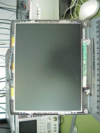
Click to zoom
Application Details
- Equipment Class
- DSS - Part 15 Spread Spectrum Transmitter
- Date of Grant
- Jul 19, 2001
- Application Purpose
- Original Equipment
- Date of Application
- Jul 19, 2001
- Equipment Note
- Bluetooth Module
- Frequency Range
- 2402.00000000 - 2483.50000000
- Company
- Dynabook Inc.
- Country
- Japan
Documents & Files
Document Text
Text extracted from the exhibit documents filed with the FCC. Open a document above to read the original.
Users Manual
Installing Bluetooth 1 / 2 Installing Bluetooth To install the internal Bluetooth, follow the procedures below. Removing the battery pack Before installing the Bluetooth board, remove the battery pack. Installing the Bluetooth board To install the Bluetooth board, follow the steps below and refer to Figure 1 and Figure 2. 1. Remove one screw securing the Bluetooth board cover. 2. Remove the Bluetooth board cover. Figure 1 Removing the Bluetooth board cover 3. Connect the antenna cable to the Bluetooth board. Installing Bluetooth 2 / 2 4. Align the board’s connector with the connector on the computer. Press the board carefully and firmly to ensure a solid connection. Figure 2 Installing the Bluetooth board 5. Seat the Bluetooth Board cover and secure it with one screw. Installing the battery pack Install the battery pack. No.5T03679C TOSHIBA TOSHIBA CORPORATION TOTAL 36 CONT. ON 2 PAGE NO. 1 Functional Specifications of Toshiba Bluetooth Utility Version 1.0 TOSHIBA CORPORATION No.5T03679C TOSHIBA TOSHIBA CORPORATION CONT. ON PAGE NO. 2 Title: Functional Specifications of TOSHIBA Bluetooth Utility Version 1.0 REV No. DATE CONTENTS DEP. REVISED APP'D STGE.PER. 00 00/09/20 Initial draft (PS5) Tada No.5T03679C TOSHIBA TOSHIBA CORPORATION CONT. ON PAGE NO. 3 1. INTRODUCTION ........................................................................................................................................ 4 2. SUMMARY ................................................................................................................................................... 4 2.1 C OMPATIBLE O PERATING S YSTEMS ....................................................................................................... 4 2.2 L OCATION OF B LUETOOTH U TILITY ......................................................................................................... 4 2.3 U TILITY P ROGRAMS ...............................................................................................................................4 2.4 F UNCTIONS OF B LUETOOTH S ERVICE C ENTER ....................................................................................... 5 2.5 F UNCTIONS OF B LUETOOTH M ONITOR .................................................................................................... 5 2.6 F UNCTIONS OF B LUETOOTH L OCAL COM................................................................................................ 5 3. BLUETOOTH SERVICE CENTER................................................................................................................. 6 3.1 S TARTING B LUETOOTH S ERVICE C ENTER .............................................................................................. 6 3.2 B LUETOOTH S ERVICE C ENTER W INDOW ................................................................................................ 6 3.3 M ENU B AR .......................................................................................................................................... 10 3.4 U SER M ODE B AR ................................................................................................................................. 12 3.5 T OOLBAR ............................................................................................................................................ 16 3.6 R EMOTE D EVICE T REE V IEW ............................................................................................................... 21 3.7 R EMOTE D EVICE L IST V IEW ................................................................................................................. 23 3.8 R EMOTE S ERVICE L IST V IEW ............................................................................................................... 23 4. BLUETOOTH MONITOR.............................................................................................................................. 25 4.1 S TARTING B LUETOOTH M ONITOR ......................................................................................................... 25 4.2 T ASKBAR I CON .................................................................................................................................... 25 4.3 P OP - UP M ENUS ................................................................................................................................... 26 4.4 P ROPERTIES ....................................................................................................................................... 27 5. BLUETOOTH LOCALCOM.......................................................................................................................... 31 5.1 S TARTING B LUETOOTH L OCAL COM..................................................................................................... 31 5.2 L OCAL COM W INDOW ......................................................................................................................... 31 5.3 L OCAL COM S ETUP W IZARD ................................................................................................................ 33 5.4 C REATING A L OCAL COM S ERVER ....................................................................................................... 34 5.5 C REATING A L OCAL COM C LIENT ......................................................................................................... 35 5.6 C ONNECTING TO A R EMOTE S ERVICE ................................................................................................... 35 No.5T03679C TOSHIBA TOSHIBA CORPORATION CONT. ON PAGE NO. 4 1. Introduction This document contains the functional specifications for the Toshiba Bluetooth Utility. 2. Summary This section contains a summary of the Toshiba Bluetooth Utility. 2.1 Compatible Operating Systems The Bluetooth Utility can be used with one of these Microsoft operating systems: Windows 95, Windows 98 or Windows 98SE, Windows ME, Windows NT 4.0 with Service Pack 6, or Windows 200…
Text truncated - open the document above for the full version.
Cover Letter(s)
Application CJ6PA3121BT Request for Limited Modular Approval Part 15 Unlicensed Modular Transmitter Approval Justification per DA 00-1407, released: June 26, 2000 RequirementReference 1. The modular transmitter must have its own RF shielding. See Exhibit 3 and Exhibit 9 2. The modular transmitter must have buffered modulation/data inputs All inputs to the modules are buffered through logic or microprocessor inputs. See Exhibit 5. 3. The modular transmitter must have its own power supply regulation. All power lines derived from the host device are regulated before energizing other circuits internal to the EUT. See Exhibit 5. 4. The modular transmitter must comply with the antenna requirements of Section 15.203 and 15.204(c). The EUT will be inbuild into host equipment, which has antenna built-in, which is inaccessible to the user. See Exhibit 3 Antenna Position and Exibit 13 DoEU 5. The modular transmitter must be tested in a stand-alone configuration, i.e., the module must not be inside another device during testing. Please refer to Exhibit 6 6. The modular transmitter must be labeled with its own FCC ID number, and, if the FCC ID is not visible when the module is installed inside another device, then the outside of the device into which the module is installed must also display a label referring to the enclosed module. The EUT carries an FCC ID label whose artwork and label position are clearly indicated; see Exhibit 1 exhibits. In addition the label for the host equipment is shown. 7. The modular transmitter must comply with any specific rule or operating requirements applicable to the transmitter and the manufacturer must provide adequate instructions along with the module to explain any such requirements. A copy of these instructions must be included in the application for equipment authorization. The EUT incorporates a Bluetooth Module whose 15.247 spread spectrum frequency hopping functional parameters cannot be altered by the user. See Exhibit 12. 8. The modular transmitter must comply with any applicable RF exposure requirements. For example, FCC Rules in Sections 2.1091, 2.1093 and specific Sections of Part 15, including 15.319(i), 15.407(f), 15.253(f) and 15.255(g), require that Unlicensed PCS, UNII and millimeter wave devices perform routine environmental evaluation for RF Exposure to demonstrate compliance. In addition, spread spectrum transmitters operating under Section 15.247 are required to address RF Exposure compliance in accordance with Section 15.247(b)(4). RF output is 1 mW and constitutes no RF exposure hazard. RF Safety statements are provided in the Exhibit 13
External Photos
CETECOM ICT Services GmbH Test report nr.:2-2509-E/01Issue date:05.06.2001Page 75 (79) Equipment under test : Bluetooth module Ambient temperature : 23° °° °C Relative humidity : 47% PHOTOGRAPHS OF THE EQUIPMENT Photograph no.: 6 (Antenna) CETECOM ICT Services GmbH Test report nr.:2-2509-E/01Issue date:05.06.2001Page 76 (79) Equipment under test : Bluetooth module Ambient temperature : 23° °° °C Relative humidity : 47% PHOTOGRAPHS OF THE EQUIPMENT Photograph no.: 7 (antenna placement)
ID Label/Location Info
Regulatory Label of Bluetooth on bottom of PC Regulatory Label of Bluetooth module
Internal Photos
Application CJ6PA3121BT Exhibit 9: Internal Photographs Application CJ6PA3121BT Exhibit 9: Internal Photographs
Test Report
CETECOM ICT Services GmbH Radio Satelite Communication Untertürkheimer Straße 6-10 . D-66117 SaarbrückenTelefon: +49 (0)681 598-9100Telefax: -9075 RSC14issue test report consist of80 PagesPage 1 (80) Test report no.: 2-2509-E/01 FCC Part15.247/CANADA RSS-210 Bluetooth module Accredited Testing Laboratory DAR-Registration number: TTI-P-G 166/98-00 CETECOM ICT Services GmbH Radio Satelite Communication Untertürkheimer Straße 6-10 . D-66117 SaarbrückenTelefon: +49 (0)681 598-9100Telefax: -9075 RSC14issue test report consist of80 PagesPage 2 (80) Table of Contents 1 General information 1.1 Notes 1.2 Testing laboratory 1.3 Details of applicant 1.4 Application details 1.5 Test item 1.6 Test standards 2 Technical test 2.1 Summary of test results 2.2 Test report 1 General information 1.1 Notes The test results of this test report relate exclusively to the test item specified in 1.5. The CETECOM ICT Services GmbH does not assume responsibility for any conclusions and generalisations drawn from the test results with regard to other specimens or samples of the type of the equipment represented by the test item. The test report may only be reproduced or published in full. Reproduction or publication of extracts from the report requires the prior written approval of the CETECOM ICT Services GmbH. 1.2Testing laboratory CETECOM ICT Services GmbH 66117 Saarbrücken Untertürkheimer Straße 6 - 10 Deutschland Telefone: + 49 681 598 - 0 Telefax : + 49 681 598 - 9075 E-mail : [email protected] Internet : www.cetecom.de Accredited testing laboratory DAR-registration number : TTI-P-G 166/98-20 CETECOM ICT Services GmbH Test report no.: 2-2509-E/01Issue Date: 05.06.2001Page 3 (80) Equipment under test : Bluetooth module Ambient temperature : 23° °° °C Relative humidity : 47% 1.3Details of applicant Name :Technology & Quality Management Division, Toshiba Corporation, Digital Media Network Company Street :1-1-1 Shibaura City :Minarto-ku, Tokyo 198-8001 Country :Japan Telephone:+81 (3) 3457 2565 Telefax :+81 (3) 5444 9404 Contact :Mr. Hideo Abe Telephone:+81 (3) 3457 2565 1.4Application details Date of receipt of application : 23.04.01 Date of receipt of test item : 23.04.01 Date of test : 24.04. – 26.04.01 1.5Test item Type of equipment : Bluetooth module for integration into PC`s Type designation: Manufacturer: - applicant - Street: City: Country: Serial number: Additional informations: : Frequency:2402 – 2480 MHz Type of modulation:1M00FXD (FHSS) Ch.Sep. : 1 MHz Number of channels :79 Antenna:integral antenna Power supply:5.0 DC powered by USB port Output power cond.:1 mW Type of equipment:Class B Temperature range :+5°C - +35°C 1.6Test standards: FCC Part 15 §15.247 CETECOM ICT Services GmbH Test report no.: 2-2509-E/01Issue Date: 05.06.2001Page 4 (80) Equipment under test : Bluetooth module Ambient temperature : 23° °° °C Relative humidity : 47% 2 Technical test 2.1Summary of test results For the measurements, the module was powered by a Toshiba laptop Satellite 4600 Pro or an external PCB test board. The radiated measurements were performed with the antenna positioned outside and inside the laptop. The radiated measurements were performed horizontal, vertical results are about 6 dB lower over the complete frequency range. The antenna gain measurement was performed by the difference between conducted and radiated output measurement. The conducted power measurement was performed by a temporary added coax adapter. All measurement settings are according to FCC 15.35, 15.205, 15.209, 15.247 and the „Measurement guidelines for FHSS systems“. No deviations from the technical specification(s) were ascertained in the course of the tests performed. The product fullfills also the requirements for CANADA RSS-210. Technical responsibility for area of testing : 05.06.2001RSC 8414 Ames H. DateSectionNameSignature Technical responsibility for area of testing : 05.06.2001RSC8412Hausknecht D. DateSectionNameSignature CETECOM ICT Services GmbH Test report no.: 2-2509-E/01Issue Date: 05.06.2001Page 5 (80) Equipment under test : Bluetooth module Ambient temperature : 23° °° °C Relative humidity : 47% 2.2Testreport TEST REPORT Testreport no. : 2-2509-E/01 CETECOM ICT Services GmbH Test report no.: 2-2509-E/01Issue Date: 05.06.2001Page 6 (80) Equipment under test : Bluetooth module Ambient temperature : 23° °° °C Relative humidity : 47% TEST REPORT REFERENCE LIST OF MEASUREMENTS ParagraphPARAMETER TO BE MEASUREDPAGE T RANSMITTER PARAMETERS § 15.204Antenna gain7 § 15.247 (a)Carrier frequency separation8 § 15.247 (a)Number of hopping channels9 § 15.247 (a)Time of occupancy (dwell time)13 § 15.247 (a)(1)Spectrum bandwidth of a FHSS System20 § 15.247 (b)(2)Maximum peak output power24 §15.247Band edge compliance29 § 15.247 (c)(1)Emission limitations 33 § 15.107/207Low frequency emissions59 R ECEIVER PARAMETERS § 15.209Spurious radiations - Radiated61 Test equipment listing68 Photographs of the equipment70 CETECOM ICT Services GmbH Test report no.: 2-2509-E/01Issue Date: 05.06.2001Page 7 (80) Equipment under test : Bluetooth module Ambient temperature : 23° °° °C Relative humidity : 47% Antenna GainSUBCLAUSE § 15.204 The antenna gain of the complete system is calculated by the difference of conducted power of the module and the radiated power in EIRP. low channelmid channelhigh channel Conducted power-2.99 dBm-3.19 dBm-2.7dBm Radiated power (antenna outside) -1.94 dBm-2.07 dBm-1.61 dBm Gain+1.05 dBm +1.12 dBm+1.09 dBm Radiated power (antenna inside laptop) -6.2 dBm -6.3 dBm-6.5 dBm Gain-3.21 dB-3.11 dB-3.8 dB The calculated antenna gain is between –3.11 and –3.8 dB for the build-in antenna And between +1.05 and +1.12 dB for the stand-alone antenna outside housing. When the module and the dedicated antenna are met in a computer, the radiated power is lower because of metallic parts near the antennas. CETECOM ICT Services GmbH Test report no.: 2-2509-E/01Issue Date: 05.06.2001Page 8 (80) Equipment under test : Bluetooth module Ambi…
Text truncated - open the document above for the full version.
Test Report
CONFIDENTIAL 73 0004 R00A Processing Gain Measurement Report WP Silicon Wave, Inc. PROCESSING GAIN MEASUREMENT RESULTS OF SILICON WAVE’S BLUETOOTH™ RADIO MODEM USING THE CW-JAMMING MARGIN METHOD Abstract This document provides results of the processing gain measurements for the Silicon Wave Bluetooth reference design platform when measured in accordance with the FCC’s CW- jamming margin method. Because the page and inquiry modes of a Bluetooth system use a fixed access code across fewer than 75 frequencies, it is considered a hybrid system that em- ploys a combination of both direct sequence and frequency hopping modulation techniques and therefore must achieve a processing gain of at least 17 dB from the combined techniques. The contribution to the processing gain caused by the three unique access codes used in this report is no more than 4 dB, and the calculated contribution from the frequency hopping part is 15 dB. The conclusion: the Silicon Wave Bluetooth reference design platform passes the processing gain test with a margin of at least 2 dB using a random (typical) access code and a margin of approximately 1 dB using a worst-case access code. Processing Gain Measurement Report White Paper June 14, 2001 CONFIDENTIAL 73 0004 R00A Processing Gain Measurement Report WP Page ii Silicon Wave, Inc. Table of Contents 1. INTRODUCTION ................................................................................................................................1 2. DESCRIPTION ...................................................................................................................................1 2.1 FCC Reference ...............................................................................................................................1 2.2 Bluetooth Access Code...................................................................................................................2 2.3 System Losses................................................................................................................................3 3. MEASURED RESULTS......................................................................................................................3 3.1 Procedure........................................................................................................................................3 3.2 Signal to Noise Measurement .........................................................................................................3 3.3 Jammer-to-Signal Measurement.....................................................................................................3 3.4 Test System Equipment List ...........................................................................................................4 3.5 Results ............................................................................................................................................6 3.5.1 Test Case 1 .................................................................................................................................7 3.5.2 Test Case 2 .................................................................................................................................8 3.5.3 Test Case 3 .................................................................................................................................9 4. CONCLUSION....................................................................................................................................9 List of Tables and Figures Table 1: Equipment List................................................................................................................................4 Table 2: Failed Reject Ratio (FRR) Results by Access Code and Frequency Offset ..................................6 Figure 1: Test System Block Diagram ..........................................................................................................5 Figure 2: Jammer Offset and FRR for LAP of 000000 .................................................................................7 Figure 3: Jammer Offset and FRR for LAP of FFFFFF................................................................................8 Figure 4: Jammer Offset and FRR for LAP of 9B415C ................................................................................9 Revision History Revision Date Author Description R00A June 14, 2001 M. Mester Initial release. Processing Gain Measurement Report White Paper June 14, 2001 CONFIDENTIAL 73 0004 R00A Processing Gain Measurement Report WP Page 1 of 10 Silicon Wave, Inc. 1. INTRODUCTION The FCC requires evidence of compliance to Section 15.247 (f) where a hybrid system that employs a combinations of both direct sequence and frequency hopping modulation techniques achieve a process- ing gain of at least 17 dB from the combined techniques. The FCC prefers that measured results be pro- vided for the direct sequence part using a continuous wave (CW) jamming margin method. Silicon Wave has performed these measurements using the Silicon Wave Wireless Development System (WDS) that includes the reference design circuits used to implement its Bluetooth system. This white paper describes the method used to obtain the measured results using the WDS and the results that show the contribution of the direct sequence to processing gain is approximately 3 to 4 dB (depending on access code). There- fore, we conclude that the Silicon Wave Bluetooth system exceeds the required 17 dB processing gain with approximately 1 dB of margin using the worst-case access code. The procedure followed in this white paper closely matches the method used by Ericsson outlined in their white paper titled "Processing Gain Measurement Results of Ericsson’s Bluetooth Radio Module Using The CW-Jamming Margin Method" available from the FCC website located at http://www.fcc.gov/oet/fccid . Section 2 (Description) details the CW-jamming method used to provide the measured results…
Text truncated - open the document above for the full version.
Test Setup Photos
CETECOM ICT Services GmbH Test report nr.:2-2509-E/01Issue date:05.06.2001Page 70 (79) Equipment under test : Bluetooth module Ambient temperature : 23° °° °C Relative humidity : 47% PHOTOGRAPHS OF THE EQUIPMENT Photograph no.: 1 (Testsite) CETECOM ICT Services GmbH Test report nr.:2-2509-E/01Issue date:05.06.2001Page 71 (79) Equipment under test : Bluetooth module Ambient temperature : 23° °° °C Relative humidity : 47% PHOTOGRAPHS OF THE EQUIPMENT Photograph no.: 2 (Testsite) CETECOM ICT Services GmbH Test report nr.:2-2509-E/01Issue date:05.06.2001Page 72 (79) Equipment under test : Bluetooth module Ambient temperature : 23° °° °C Relative humidity : 47% PHOTOGRAPHS OF THE EQUIPMENT Photograph no.: 3 (Testsite)
Contact Information
Applicant
Ryuichi Kamimura(Senior Manager)
Technical Contact
Non-Technical Contact
CETECOM GmbHThorsten Stabenau
[email protected]+4920549519974
Test Firm
CETECOM GmbHWolfgang Richter
Technical Specifications
| # | Rule Parts | Frequency Range | Power Output |
|---|---|---|---|
| 1 | 15C | 2.40 GHz - 2.48 GHz | 1.00 mW |
Other Applications from Dynabook Inc.

CJ6PA5347RT
Oct 20, 2022dynabook Wireless Optical Silent Mouse
Equipment Class
DXX - Part 15 Low Power Communication Device Transmitter
CJ6PYT0XPC
Apr 28, 2021Notebook Computer
Equipment Class
DSS - Part 15 Spread Spectrum Transmitter
CJ6UPA5238WL
Sep 01, 2015dynadock WiAC
Equipment Class
NII - Unlicensed National Information Infrastructure TX
CJ6UPA5144TJ
Aug 07, 2014TransferJet USB Adapter
Equipment Class
JBP - Part 15 Class B Computing Device Peripheral
CJ6UPA5145TJ
Aug 07, 2014TransferJet MicroUSB Adapter
Equipment Class
UWB - Ultra Wideband Transmitter