CJ6PA3171WLWireless LAN, limited module approval
Dynabook Inc.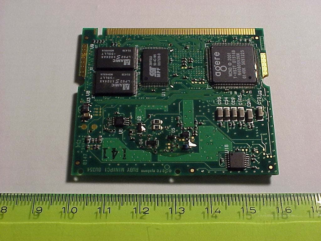
Click to zoom
Application Details
- Equipment Class
- DSS - Part 15 Spread Spectrum Transmitter
- Date of Grant
- Feb 05, 2002
- Application Purpose
- Original Equipment
- Date of Application
- Dec 03, 2001
- Equipment Note
- Wireless LAN, limited module approval
- Frequency Range
- 2412.00000000 - 2462.00000000
- Company
- Dynabook Inc.
- Country
- Japan
Documents & Files
Document Text
Text extracted from the exhibit documents filed with the FCC. Open a document above to read the original.
Users Manual
Toshiba Wireless LAN mini-PCI Card – Getting started 1-1 About Toshiba Wireless Solution 1 Wireless LAN Network Scenarios The Wireless LAN Card Kit enables you to: n Connect your computer to a Peer-to-Peer workgroup of wireless computing devices. n Connect your computer to a Local Area Network (LAN) Infrastructure that includes Wireless LAN Access Points, or other IEEE802.11 compliant LAN systems. n Expand the capabilities of your Wireless LAN Access Points, to support wireless devices that have been equipped with Wireless LAN Card. NOTE: The internal Wireless LAN Card can’t be used with the Toshiba Wireless LAN PC Card. Toshiba Wireless LAN mini-PCI Card – Getting started 1-2 Peer-to-Peer Workgroup The Peer-to-Peer workgroup configuration enables you to quickly set up a small wireless workgroup, where the workgroup participants can exchange files using features like “Files and Printer Sharing” as supported by Microsoft Networking. Figure 1-1 Peer-to-Peer Wireless Workgroup You can use this option to setup a temporary or ad-hoc network in environments where no access points are available (for example in Small Office/Home Office (SOHO) environments). As long as the stations are within range of one another, this is the easiest and least expensive way to set up a wireless network. Toshiba Wireless LAN mini-PCI Card – Getting started 1-3 Enterprise Networking Figure 1-2 Stand Alone Wireless LAN With the Wireless LAN Access Points you can connect to a corporate Local Area Network (LAN) infrastructure to have wireless access to all network facilities. LAN Infrastructures may either be. n Stand-alone wireless LANs as pictures in Figure 1-2 n Wireless network infrastructures connected to an existing Ethernet network as pictured in Figure 1-3. Toshiba Wireless LAN mini-PCI Card – Getting started 1-4 Figure 1-3 LAN Infrastructure Toshiba Wireless LAN mini-PCI Card – Getting started 1-5 It’s Easy The Wireless LAN Card functions like any standard wired Ethernet card, but Wireless LAN does not need any wires! Where an Ethernet card requires a cable connection to a hub and/or patch panel, the cable physically ties you down to the location of the wired connection. Wireless LAN allows you connect your computer to a Local Area Network (LAN) system from anywhere within the wireless coverage area. Expanding or re-designing your network is easy: Add or relocate Wireless LAN Access Points, power-up your (new) Wireless LAN computers, and you’re done! Unlike Ethernet, Wireless LAN will enable you to roam throughout the network while remaining connected to the LAN. NOTE: The Wireless LAN Card is a radio product. Refer to the flyer “Information to the User” for regulatory information that may apply in your country. Toshiba Wireless LAN mini-PCI Card – Getting started 1-6 Wireless LAN Card Features Toshiba Wireless LAN mini-PCI Card is a wireless network card that fits into Mini PCI TypeIIIA. Toshiba Wireless LAN mini-PCI Card – Getting started 1-7 Wireless LAN Card Types The Wireless LAN Card is a wireless network card that complies with the IEEE 802.11 standard on wireless LANs (Revision B). The Wireless LAN Card supports data rates up to 11 Mbit/s. n Wi-Fi (Wireless Fidelity) certified by the Wireless Ethernet Compatibility Alliance (WECA). This means that your Wireless hardware will communicate with other vendors’ IEEE 802.11 compliant wireless LAN product. n Fully compatible with any other wireless LAN system based on Direct Sequence Spread Spectrum (DSSS) radio technology that complies with the “IEEE 802.11 standard on wireless LANs (Revision B). Toshiba Wireless LAN mini-PCI Card – Getting started 1-8 Wireless LAN Cards The Wireless LAN Card supports the following wireless LAN features: n Automatic Transmit Rate Select mechanism in the transmit range of 11, 5.5, 2 and 1 Mbit/s. n Frequency Channel Selection (2.4GHz). n Roaming over multiple channels. n Card Power Management. n Wired Equivalent Privacy (WEP) data encryption, based on the 128 bit RC4 encryption algorithm. Toshiba Wireless LAN mini-PCI Card – Getting started 1-9 Finding Information This document was designed to give you a brief introduction about the Wireless LAN Card. In this document you will find the most important information to get your Wireless LAN network up and running, with a minimum set of parameters. Alternatively you can consult the on-line help documentation for the Wireless LAN drivers and/or tools by: n Clicking the [Help] button on your screen, or n Pressing the [F1] function key on your keyboard. Toshiba Wireless LAN mini-PCI Card – Getting started 1-10 Basic Settings for Enterprise Networks If you wish to connect to an Enterprise Network, use the Add/Edit Configuration Profile window to: n Click the start button from the Windows task bar. n Click on Settings, and then on Control Panel. n In the Control Panel window, double-click the Wireless Network icon. n Select to connect to an Access Point. n Set the correct Network Name. Figure 1-4 Edit Configuration window Toshiba Wireless LAN mini-PCI Card – Getting started 1-11 1. In the field Network Name define the name of the wireless network to which you want to connect. You can either use: n The value “ANY” To connect to any wireless LAN network in the vicinity of your computer. n An “exact” value to connect to Consult your LAN Administrator for the value that applies to your network. The Network Name can be any alphanumeric string in the range of “a” to “z”, “A” to “Z” and “0” to “9” with a maximum of 32 characters (case-sensitive). 2. Click OK to confirm and return to the Add/Edit Configuration Profile window. 3. Click OK again to finish. Toshiba Wireless LAN mini-PCI Card – Getting started 1-12 Basic Settings for Peer-to-Peer Workgroups If you wish to connect to a Peer-to-Peer workgroup, use the Add/Edit Configuration Profile window to: n Click the start button from the Windows task bar. n Click on Settings, and then on Control Panel. n In the Control Panel window, double-cli…
Text truncated - open the document above for the full version.
Users Manual
This sheet is for information only. The wireless LAN card must be installed by your hardware dealer. Contains FCC ID: CJ6PA3171WL 3171U
Users Manual
This sheet is for information only. The wireless LAN card must be installed by Toshiba or Toshiba OEM dealers.
Cover Letter(s)
Application CJ6PA3171WL Request for Limited Modular Approval for Toshiba W-LAN module with three different antenna types The W-LAN Module is for intended use in Toshiba Products only Part 15 Unlicensed Modular Transmitter Approval Justification per DA 00-1407, released: June 26, 2000 Requirement Reference 1. The modular transmitter must have its own RF shielding. See Exhibit 3 and Exhibit 9 2. The modular transmitter must have buffered modulation/data inputs All inputs to the modules are buffered through logic or microprocessor inputs. See Exhibit 5. 3. The modular transmitter must have its own power supply regulation. All power lines derived from the host device are regulated before energizing other circuits internal to the EUT. See Exhibit 5. 4. The modular transmitter must comply with the antenna requirements of Section 15.203 and 15.204(c). The EUT will be inbuild into host equipment, which has antenna built-in, which is inaccessible to the user. See Exibit 8 Installation Instructions 5. The modular transmitter must be tested in a stand-alone configuration, i.e., the module must not be inside another device during testing. Please refer to Exhibit 6 6. The modular transmitter must be labeled with its own FCC ID number, and, if the FCC ID is not visible when the module is installed inside another device, then the outside of the device into which the module is installed must also display a label referring to the enclosed module. The EUT carries an FCC ID label whose artwork and label position are clearly indicated; see Exhibit 1 exhibits. In addition the label for the host equipment is shown. 7. The modular transmitter must comply with any specific rule or operating requirements applicable to the transmitter and the manufacturer must provide adequate instructions along with the module to explain any such requirements. A copy of these instructions must be included in the application for equipment authorization. See Exhibit 12. The modular transmitter must comply with any applicable RF exposure requirements. For example, FCC Rules in Sections 2.1091, 2.1093 and specific Sections of Part 15, including 15.319(i), 15.407(f), 15.253(f) and 15.255(g), require that Unlicensed PCS, UNII and millimeter wave devices perform routine environmental evaluation for RF Exposure to demonstrate compliance. In addition, spread spectrum transmitters operating under Section 15.247 are required to address RF Exposure compliance in accordance with Section 15.247(b)(4). RF Safety statements are provided in: Exhibit 11 RF Exposure statement Exhibit 11 SAR Report Exhibit 11 MPE Prediction
External Photos
Application CJ6PA3171WL CETECOM GmbH, Essen, Germany Exhibit 3: External Photographs Rear side Front side – with RF shielding
External Photos
Application CJ6PA3171WL CETECOM GmbH, Essen, Germany Exhibit 3: External Photographs Rear side Front side – with RF shielding
ID Label/Location Info
Bottom side view Regulatory Label Regulatory Label of Wireless LAN on bottom of PC PA3171U-1MPU Contains FCC ID: CJ6PA3171WL Regulatory Label on Mini PCI Wireless LAN Card Regulatory Label Label with S/N, P/N and MAC address: SSSSSSSSSSSS = Agere S/N; human readable and barcode. 019045/X= P/N with related rev. level (y). P/N represents H/W and F/ W configuration. ZAxxxxPxx and PAxxxxx-1MPC are Toshiba product numbers. FCC : CJ63171WL Label with S/N, P/N and MAC address Mini PCI Label Placement (front side) Regulatory Label
ID Label/Location Info
Bottom side view Regulatory Label Regulatory Label of Wireless LAN on bottom of PC PA3171U-1MPC Contains FCC ID: CJ6PA3171WL Regulatory Label on Mini PCI Wireless LAN Card Regulatory Label Label with S/N, P/N and MAC address: SSSSSSSSSSSS = Agere S/N; human readable and barcode. 019045/X= P/N with related rev. level (y). P/N represents H/W and F/ W configuration. ZAxxxxPxx and PAxxxxx-1MPC are Toshiba product numbers. FCC : CJ6PA3171WL Label with S/N, P/N and MAC address Mini PCI Label Placement (front side) Regulatory Label
Internal Photos
Application CJ6PA3171WL Dipl.-Ing. Karin Silberhorn CETECOM GmbH, Essen, Germany Exhibit: External/ Internal Photographs Rear side Front Side Application CJ6PA3171WL Dipl.-Ing. Karin Silberhorn CETECOM GmbH, Essen, Germany Front view Module with Dual Film Antenna Rear view Module with Dual Film Antenna Application CJ6PA3171WL Dipl.-Ing. Karin Silberhorn CETECOM GmbH, Essen, Germany Front view Module with Film Antenna Rear view Module with Dual Film Antenna Application CJ6PA3171WL Dipl.-Ing. Karin Silberhorn CETECOM GmbH, Essen, Germany Front view Module with Stick on Antenna Rear view Module with Stick on Antenna
Internal Photos
Application CJ6PA3171WL Dipl.-Ing. Karin Silberhorn CETECOM GmbH, Essen, Germany Exhibit: External/ Internal Photographs Rear side Front Side Application CJ6PA3171WL Dipl.-Ing. Karin Silberhorn CETECOM GmbH, Essen, Germany Front view Module with Dual Film Antenna Rear view Module with Dual Film Antenna Application CJ6PA3171WL Dipl.-Ing. Karin Silberhorn CETECOM GmbH, Essen, Germany Front view Module with Film Antenna Rear view Module with Dual Film Antenna Application CJ6PA3171WL Dipl.-Ing. Karin Silberhorn CETECOM GmbH, Essen, Germany Front view Module with Stick on Antenna Rear view Module with Stick on Antenna
Internal Photos
Application CJ6PA3171WL Dipl.-Ing. Karin Silberhorn CETECOM GmbH, Essen, Germany Exhibit: External/ Internal Photographs Rear side Front Side – with RF shielding Application CJ6PA3171WL Dipl.-Ing. Karin Silberhorn CETECOM GmbH, Essen, Germany Front Side – without RF shielding Front view Module with Dual Film Antenna Application CJ6PA3171WL Dipl.-Ing. Karin Silberhorn CETECOM GmbH, Essen, Germany Rear view Module with Dual Film Antenna Front view Module with Film Antenna Application CJ6PA3171WL Dipl.-Ing. Karin Silberhorn CETECOM GmbH, Essen, Germany Rear view Module with Dual Film Antenna Front view Module with Stick on Antenna Application CJ6PA3171WL Dipl.-Ing. Karin Silberhorn CETECOM GmbH, Essen, Germany Rear view Module with Stick on Antenna
Internal Photos
Application CJ6PA3171WL CETECOM GmbH, Essen, Germany Exhibit 9: Internal Photographs Rear side Front side – without RF shielding Application CJ6PA3171WL CETECOM GmbH, Essen, Germany Front and rear view ‘Dual Film Antenna’ Front and rear view ‘Film Antenna’ Application CJ6PA3171WL CETECOM GmbH, Essen, Germany Front and rear view ‘Stick on Antenna’
Internal Photos
Application CJ6PA3171WL CETECOM GmbH, Essen, Germany Exhibit 9: Internal Photographs Rear side Front side – without RF shielding Application CJ6PA3171WL CETECOM GmbH, Essen, Germany Front and rear view ‘Dual Film Antenna’ positioning of ‘Dual Film Antenna’ Application CJ6PA3171WL CETECOM GmbH, Essen, Germany Front and rear view ‘Film Antenna’ positioning of ‘Film Antenna’ Application CJ6PA3171WL CETECOM GmbH, Essen, Germany Front and rear view ‘Stick On Antenna’ positioning of ‘Stick On Antenna’
RF Exposure Info
CETECOM ICT Services GmbH Untertuerkheimer Str. 6-10, 66117 Saarbruecken, GermanyPhone: +49 (0) 681 598-0Fax: -9075 SAR-LaboratoryPhone: +49 (0) 681 598-8454Fax: -8475 Test report no.:4-0492-1-1/01 Type identification :Portege 2000 FCC id:CJ6PA3171WL Accredited EMC-Test-Laboratory accredited by: Regulatory Authority for Telecommunications and Posts (Reg TP) DAR-No.: TTI-P-G-166/98-30 Federal Motor Transport Authority (KBA) DAR registration number: KBA-P 00070-97 from January –19-1999 Listed by FEDERAL COMMUNICATIONS COMMISSION (FCC ) Registration Number: 90462 FCC Website: WWW.FCC.GOV CETECOM ICT Services GmbH Test report no.: 4-0492-01-01/01date: 2001-12-03Page 2 of 27 Table of Content 1 General Information......................................................................................3 1.1 Notes.................................................................................................................................3 1.2 Statement of Compliance....................................................................................................3 1.3 Testing laboratory...............................................................................................................4 1.4 Details of applicant.............................................................................................................4 1.5 Application details..............................................................................................................4 1.6 Test item............................................................................................................................5 1.7 Test specifications...............................................................................................................6 1.7.1 RF exposure limits.......................................................................................................6 2 Technical test...............................................................................................7 2.1. Summary of test results......................................................................................................7 2.2 Test environment................................................................................................................7 2.3 Test equipment used...........................................................................................................7 2.4 Test results (Body SAR).....................................................................................................8 2.5 Tissue dielectric properties..................................................................................................9 2.6 Tissue parameters...............................................................................................................9 2.7 Measurement uncertainties................................................................................................10 2.8 System validation..............................................................................................................11 Appendix 1: System performance verification.................................................12 Appendix 2: Measurement results (printout from DASY TM )............................13 Appendix 3: Photo documentation.................................................................17 Appendix 4: Calibration parameters of E-field probe.......................................26 CETECOM ICT Services GmbH Test report no.: 4-0492-01-01/01date: 2001-12-03Page 3 of 27 1 General Information 1.1 Notes The test results of this test report relate exclusively to the test item specified in 1.6. The CETECOM ICT Services GmbH does not assume responsibility for any conclusions and generalisations drawn from the test results with regard to other specimens or samples of the type of the equipment represented by the test item. The test report may only be reproduced or published in full. Reproduction or publication of extracts from the report requires the prior written approval of the CETECOM ICT Services GmbH. 1.2 Statement of Compliance The SAR values found for the laptop with Wlan card Portege 2000 are below the maximum recommended levels of 1.6 W/Kg as averaged over any 1 g tissue according the FCC rule §2.1093, the ANSI/IEEE C 95.1:1999 and the NCRP Report Number 86 for uncontrolled environment. Tester operator: 2001-12-03Fabien Coulet DateNameSignature Technical responsibility for area of testing: 2001-12-03Bernd Rebmann DateNameSignature CETECOM ICT Services GmbH Test report no.: 4-0492-01-01/01date: 2001-12-03Page 4 of 27 1.3 Testing laboratory CETECOM ICT Services GmbH Untertürkheimer Straße 6-10, D-66117 Saarbrücken Germany Telephone:+49 681 598 - 0 Fax:+ 49 681 598 - 8475 e-mail:[email protected] Internet:http://www.cetecom.com State of accreditation: The Test laboratory SAR is accredited according to DIN EN ISO / IEC 1702545001. DAR-No.:TTI-P-G-166/98-30 Test location, if different from CETECOM ICT Services GmbH Name: --- Street: --- Town: --- Country: --- Phone: --- Fax: --- 1.4 Details of applicant Name: TOSHIBA Corporation Digital Media Network Company Ome Operations-Digital Media Equipment Street: 2-9, SUEHIRO-CHO, OME Town: TOKYO, 198-8710 Country:Japan Contact: Mr. KOICHI KAJI Phone: +81-428-30-7432 Fax: +81-428-34-1445 1.5 Application details Date of receipt of application: 13.11.2001 Date of receipt of test item: 13.11.2001 Date of test: 20.11.2001 Person who have been present during the test: --- CETECOM ICT Services GmbH Test report no.: 4-0492-01-01/01date: 2001-12-03Page 5 of 27 1.6 Test item Description of test item: EUT Type:Laptop with integrated WLAN card (Mini PCI) Trade Name:Toshiba Model:Portege 2000 SW:-- Frequency:2402-2483.5 MHz here 2412-2462 MHz Modulation:22M0P7D (DSSS) ch steps: 5 MHz Number of channels:11 Max RF output power:83.2 mW cond. Antenna Type:integral antenna Power supply:15V DC 1.6.1 Antenna data Model Name:HTL-007-P*** Frequency Range:2.4 – 2.5 GHz Bandwidth:Over 200MHz…
Text truncated - open the document above for the full version.
RF Exposure Info
Application CJ6PA3171WL Dipl.-Ing. Karin Silberhorn CETECOM GmbH, Essen, Germany For this Application three antenna types come along with the W-LAN Module, whereof two (Film and Dual Film Antenna) are intended to be inbuilt behind the Display of Notebooks (upper border), for the third one (Stick-on Antenna) a SAR Report has been submitted. Prediction of MPE limit at given distance Equation from page 18 of OET Bulletin 65, Edition 97-01 2 4R PG S π = where: S = power density P = power input to the antenna G = power gain of the antenna in the direction of interest relative to an isotropic radiator R = distance to the center of radiation of the antenna Dual Film Antenna HTL-008 Film Antenna HTL-004 Stick-on Antenna HTL-007 Antenna Gain (dBi) 2.4 -0.8 -0.6 Prediction 1 Antenna Type: Film Antenna HTL-004 Location of Antenna: behind Display of Notebook, upper border Maximum peak output power at antenna input terminal: 19.2 dBm Maximum peak output power at antenna input terminal: 83.17637711 mW Antenna gain(typical): -0.8 dBi Maximum antenna gain: 0.831763771numeric Prediction distance: 20 cm Prediction frequency: 2400 MHz MPE limit for uncontrolled exposure at prediction frequency: 1 2 cm mW Power density at prediction frequency: 0.013763539 2 cm mW Maximum allowable antenna gain: 17,81269842 dBi Prediction 2 Antenna Type: Dual Film Antenna HTL-008 Location of Antenna: behind Display of Notebook, upper border Maximum peak output power at antenna input terminal: 19.2 dBm Maximum peak output power at antenna input terminal: 83.17637711 mW Antenna gain(typical): 2.4 dBi Maximum antenna gain: 1,7378numeric Prediction distance: 20 cm Prediction frequency: 2400 MHz MPE limit for uncontrolled exposure at prediction frequency: 1 2 cm mW Power density at prediction frequency: 0.0287561 2 cm mW Application CJ6PA3171WL Dipl.-Ing. Karin Silberhorn CETECOM GmbH, Essen, Germany This predictions, along with the following picture, demonstrate the following: 1) The power density levels at a distance of 20 cm. are well below the maximum levels allowed by the FCC regulations. 2) The distance to the antenna where 1 2 cm mW will be reached is R= 3,3915 cm (with an antenna gain of 2.4 dBi) 3) A minimum separation distance of 20 cm. can practically be maintained during normal use of the equipment as shown in picture below.
RF Exposure Info
For Wireless LAN : Caution: Exposure to Radio Frequency Radiation. The radiated output power of the TOSHIBA Wireless LAN Mini PCI Card is far below the FCC radio frequency exposure limits. Nevertheless, the TOSHIBA Wireless LAN Mini PCI Card shall be used in such a manner that the potential for human contact during normal operation is minimized. When using this device in combination with Wireless LAN Outdoor Antenna products, a certain separation distance between antenna and nearby persons has to be kept to ensure RF exposure compliance. The distance between the antennas and the user should not be less than 20cm. Refer to the Regulatory Statements as identified in the documentation that comes with those products for additional information. The TOSHIBA Wireless LAN Mini PCI Card is far below the FCC radio frequency exposure limits. Nevertheless, it is advised to use the TOSHIBA Wireless LAN Mini PCI Card in such a manner that human contact during normal operation is minimized.
RF Exposure Info
For Wireless LAN: Caution: Exposure to Radio Frequency Radiation. The Toshiba Wireless LAN Mini PCI Card will be installed with one of three types of antennas. One of these antennas, when installed will be located under the keyboard. The other two antenna types, when installed are located at the upper edge of the LCD screen. For both antennas located above the LCD, the radiated output power of the TOSHIBA Wireless LAN Mini PCI Card is far below the FCC radio frequency exposure limits. Nevertheless, the TOSHIBA Wireless LAN Mini PCI Card shall be used in such a manner that the potential for human contact during normal operation is minimized. In normal operating configuration, the LCD in the upright position, the distance between the antenna and the user should not be less than 20cm. The Toshiba Wireless LAN Mini PCI Card with the antenna located underneath the keyboard has been tested to the FCC exposure requirements (Specific Absorbtion Rate). Refer to the Regulatory Statements as identified in the documentation that comes with those products for additional information.
RF Exposure Info
1 Information sheet Wireless Interoperability The TOSHIBA Wireless LAN Mini PCI Card products are designed to be interoperable with any wireless LAN product that is based on Direct Sequence Spread Spectrum(DSSS) radio technology, and is compliant to: The IEEE 802.11 Standard on Wireless LANs(Revision B), as defined and approved by the Institute of Electrical and Electronics Engineers. The Wireless Fidelity(WiFi) certification as defined by the WECA Wireless Ethernet Compatibility Alliance. Wireless LAN and your Health Wireless LAN products, like other radio devices, emit radio frequency electromagnetic energy. The level of energy emitted by Wireless LAN devices however is far much less than the electromagnetic energy emitted by wireless devices like for example mobile phones. Because Wireless LAN products operate within the guidelines found in radio frequency safety standards and recommendations, TOSHIBA believes Wireless LAN is safe for use by consumers. These standards and recommendations reflect the consensus of the scientific community and result from deliberations of panels and committees of scientists who continually review and interpret the extensive research literature. In some situations or environments, the use of Wireless LAN may be restricted by the proprietor of the building or responsible representatives of the organization. These situations may for example include: Using the Wireless LAN equipment on board of airplanes, or In any other environment where the risk of interference to other devices or services is perceived or identified as harmful. If you are uncertain of the policy that applies on the use of wireless devices in a specific organization or environment (e.g. airports), you are encouraged to ask for authorization to use the Wireless LAN device prior to turning on the equipment. PM0003196010 2 Regulatory Information The TOSHIBA Wireless LAN Mini PCI Card must be installed and used in strict accordance with the manufacturer’s instructions as described in the user documentation that comes with the product. This device complies with the following radio frequency and safety standards. Canada – Industry Canada (IC) This device complies with RSS 210 of Industry Canada. Operation is subject to the following two conditions: (1) this device may not cause interference , and (2) this device must accept any interference, including interference that may cause undesired operation of this device.” L ‘ utilisation de ce dispositif est autorisée seulement aux conditions suivantes : (1) il ne doit pas produire de brouillage et (2) l’ utilisateur du dispositif doit étre prêt à accepter tout brouillage radioélectrique reçu, même si ce brouillage est susceptible de compromettre le fonctionnement du dispositif. The term "IC" before the equipment certification number only signifies that the Industry Canada technical specifications were met. Approval Number : 248H-DPA3171U Europe – EU Declaration of Conformity This device complies with the essential requirements of the R&TTE Directive 1999/5/EC with essential test suites as per standards: EN 60950 Safety of Information Technology equipment ETS 300 328 Technical requirements for radio equipment ETS 300 826 General EMC requirements for radio equipment. For outdoor usage only channel 10 (2457 MHz) and 11 (2462 MHz) is allowed. For private usage outside buildings across public grounds over less than 300m no special registration with IBPT/BIPT is required. Registration to IBPT/BIPT is required for private usage outside buildings across public grounds over more than 300m. An IBPT/BIPT license is required for public usage outside building. For registration and license please contact IBPT/BIPT. Gebruik buiten gebouw alleen op kanalen 10 (2457 MHz) en 11 (2462 MHz). Voor privé-gebruik buiten gebouw over publieke groud over afstand kleiner dan 300m geen registratie bij BIPT/IBPT nodig; voor gebruik over afstand groter dan 300m is wel registratie bij BIPT/IBPT nodig. Voor publiek gebruik buiten gebouwen is licentie van BIPT/IBPT verplicht. Voor registratie of licentie kunt u contact opnemen met BIPT. België/ Belgique: L’utilisation en extérieur est autorisé sur le canal 10 (2457 MHz) et 11 (2462 MHz). Dans le cas d’une utilisation privée, à l’extérieur d’un bâtiment, au-dessus d’un espace public, aucun enregistrement n’est nécessaire pour une distance de moins de 300m. Pour une distance supérieure à 300m un enregistrement auprès de I’IBPT est requise. Pour une utilisation publique à I’extérieur de bâtiments, une licence de I’IBPT est requise. Pour les enregistrements et licences, veuillez contacter I’IBPT. License required for outdoor installations. Check with reseller for procedure to follow Deutschland: Anmeldung im Outdoor-Bereich notwendig, aber nicht genehmigungspflichtig.Bitte mit Händler die Vorgehensweise abstimmen. Restricted frequency band: only channels 10 and 11 (2457 MHz and 2462 MHz respectively) may be used in France. License required for every installation, indoor and outdoor installations. Please contact ART for procedure to follow. France: Bande de fréquence restreinte : seuls les canaux 10 à 11 (2457 et 2462 MHz respectivement) doivent être utilisés en France. Toute utilisation, qu’elle soit intérieure ou extérieure, est soumise à autorisation. Vous pouvez contacter I’Autorité de Régulation des Télécommuniations (http://www.art-telecom.fr) pour la procédure à suivre. License required for indoor use. Use with outdoor installations not allowed Italia: E’necessaria la concessione ministeriale anche per l’uso interno. Verificare con i rivenditori la procedura da seguire. L’uso per installazione in esterni non e’ permessa. License required for outdoor installations. Check with reseller for procedure to follow Nederland Licentie verplicht voor gebruik met buitenantennes. Neem contact op met verkoper voor juiste procedure 3 USA-Federal Communications Commission(FCC) This device complies with Part 15 of FCC Rules. Operation of the device…
Text truncated - open the document above for the full version.
RF Exposure Info
CETECOM ICT Services GmbH Untertuerkheimer Str. 6-10, 66117 Saarbruecken, GermanyPhone: +49 (0) 681 598-0Fax: -9075 SAR-LaboratoryPhone: +49 (0) 681 598-8454Fax: -8475 Test report no.:4-0541-1-1/02 Type identification : W-LAN card ‘PA3171U-1MPC’ in TOSHIBA Notebook ‘Portege 2000’ FCC id:CJ6PA3171WL Accredited EMC-Test-Laboratory DAR-No.: TTI-P-G-166/98-30 Listed by FEDERAL COMMUNICATIONS COMMISSION (FCC ) Registration Number: 90462 FCC Website: WWW.FCC.GOV CETECOM ICT Services GmbH Test report no.: 4-0541-01-01/02date: 2002-02-04Page 2 of 28 Table of Content 1 General Informati…
Text truncated - open the document above for the full version.
Contact Information
Applicant
Ryuichi Kamimura(Senior Manager)
Technical Contact
Test Firm
CETECOM GmbHWolfgang Richter
Technical Specifications
| # | Rule Parts | Frequency Range | Power Output |
|---|---|---|---|
| 1 | 15C | 2.41 GHz - 2.46 GHz | 85.00 mW |
Other Applications from Dynabook Inc.

CJ6PA5347RT
Oct 20, 2022dynabook Wireless Optical Silent Mouse
Equipment Class
DXX - Part 15 Low Power Communication Device Transmitter
CJ6PYT0XPC
Apr 28, 2021Notebook Computer
Equipment Class
DSS - Part 15 Spread Spectrum Transmitter
CJ6UPA5238WL
Sep 01, 2015dynadock WiAC
Equipment Class
NII - Unlicensed National Information Infrastructure TX
CJ6UPA5144TJ
Aug 07, 2014TransferJet USB Adapter
Equipment Class
JBP - Part 15 Class B Computing Device Peripheral
CJ6UPA5145TJ
Aug 07, 2014TransferJet MicroUSB Adapter
Equipment Class
UWB - Ultra Wideband Transmitter