CJ6PL5080WLLibretto
Dynabook Inc.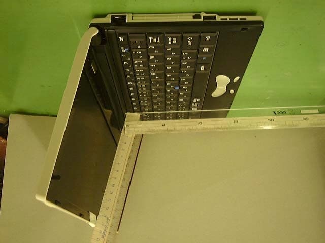
Click to zoom
Application Details
- Equipment Class
- DSS - Part 15 Spread Spectrum Transmitter
- Date of Grant
- Mar 24, 2002
- Application Purpose
- Original Equipment
- Date of Application
- Mar 24, 2002
- Equipment Note
- Libretto
- Frequency Range
- 2411.70000000 - 2462.80000000
- Company
- Dynabook Inc.
- Country
- Japan
Documents & Files
Document Text
Text extracted from the exhibit documents filed with the FCC. Open a document above to read the original.
Users Manual
APPENDIX 1.PRODUCT SPECIFICATIONS..........................................................96 2.INTERFACE SPECIFICATIONS....................................................... 101 3.TECHNICAL STANDARD COMPLIANCE........................................ 104
Users Manual
96 1. PRODUCT SPECIFICATIONS Specifications for Wireless LAN Functions ! Physical specifications Power save (doze) mode45 mA Receive mode250 mA Send mode350 mA Power3.3 V ! Wireless features The wireless features of the wireless LAN vary depending on the product you purchase and the country you are in when you purchase it. I many cases, the wireless transmission are based on the wireless regulations of the country where it is being used. Wireless network equipment is designed to use 2.4 GHz bandwidth to operate which does not require a wireless license. However, depending on the national wireless regulations, there may be several restrictions on the use of wireless network equipment. NOTE:•See the “Users Announcement” for information on the appropriate wireless regulations for each country. Wireless frequency range2.4 GHz (2400 to 2483.5 MHz) Modulator Direct diffusion format CCK (Forwarding rate; High, Medium) DQPSK (Forwarding rate; Standard) DBPSK (Forwarding rate; Low) Diffusion format11 chip Barker Sequence Bit error rate (BER)10 –5 or greater Rated output15 dBm Forwarding rate High Speed 11 Mb/s Medium Speed 5.5 Mb/s Standard Speed 2 Mb/s Low Speed 1 Mb/s Reception speed–83 dBm–87 dBm–91 dBm–94 dBm Diffusion delay (FER 1% or less) 65 ns225 ns400 ns500 ns There is a correlation function of transmission range and forwarding rate for wireless equipment. The lower the wireless transmission forwarding rate the broader the transmission range. TIPS:•Metal surfaces or dense solid bodies that are placed close to the antenna will exert an effect on the transmission range of the wireless device. •Also, if something that absorbs or reflects the wireless signal is in the path of the wireless signal, the transmission range will be effected. 97 ! Supported frequency bands The 2.4 GHz channels that the wireless LAN supports, vary depending on the applicable national wireless regulations (See the “Wireless IEEE802.11” chart). See the “Users Announcement” for information on the appropriate wireless regulations for each country. Wireless IEEE802.11 Channel Set Frequency band2400 to 2483.5 MHz *1 Channel ID 12412 22417 32422 42427 52432 62437 72442 82447 92452 102457 *1 112462 *1: The channel set at time of purchase The wireless LAN channel settings is managed in the following way: •When connected to the infrastructure with a wireless LAN, The station automatically switches to the wireless LAN access point channel. When it is roaming between different access points, the station automatically switches channels when necessary. The station switches channels between 1 and 11. It is necessary to make this the range for the wireless LAN access-point set channel. •When connecting the wireless LAN with a “peer to peer” mode, channel 10 is used. 98 Exterior Dimension Diagram * These measurements do not include protrusions. 99 Supported Video Mode The regulations that determine the maximum possible number of colors and screen resolution that is controlled by the display controller is called the video mode. All the video modes that this product supports in English mode are shown below. Usually the mode number is used by the programmer to differentiate between the various modes. When application software specifies a mode based on the mode number, that number may not match the number in the diagram. In this case, select the original resolution, font size and number of colors. Video Mode FormatResolution Font Size Number of colors CRT Refresh Rate (Hz) —800 × 600 dots—256/256K — 1024 × 768 dots *1 —256/256K 60/75/85/100 —1280 × 600 dots *1 —256/256K60 — 1280 × 1024 dots *1 —256/256K — 1600 × 1200 dots *1 —256/256K —800 × 600 dots—64K/64K — 1024 × 768 dots *1 —64K/64K 60/75/85/100 —1280 × 600 dots—64K/64K60 — 1280 × 1024 dots *1 —64K/64K60/75/85/100 —1600 × 1200 dots *1 —64K/64K60 — 800 × 600 dots —16M/16M60/75/85/100 —1024 × 768 dots *1 —16M/16M60/75/85 — 1280 × 600 dots *2 —16M/16M — SVGA Graphics 1280 × 1024 dots *2 —16M/16M 60 *1:When the display is LCD, a semblance of the screen is displayed within the actual screen (1280 × 600). (Caution) Some of the screen modes have different refresh rate modes that can not be used in multimonitor. *2:When the display is a CRT, s semblance of the screen is displayed within the actual screen (1280 × 600). 100 Hardware Resources You can confirm the memory map, I/O port map and resources that use IRQ and DMA in the following way. There are modifications depending upon the environment (hardware/software) that is being used. 1. Click [Start], [All programs], [Accessories], [System tools] and [System information]. 2. Double click on [Hardware reso urce] in the tree on the left side of the screen. 3. Click the items that you want to confirm. Memory map:[Memory] I/O port map:[I/O] Resources that use IRQ: [IRQ] Resources that use DMA: [DMA] 101 2. INTERFACE SPECIFICATIONS RGB Interface (Mini RGB Cable) Pin Number Signal nameExplanation Signal Direction 1CRVRed video signalO 2CGVGreen video signalO 3CBVBlue video signalO 4ReservedReserve 5GNDSignal ground 6GNDSignal ground 7GNDSignal ground 8GNDSignal ground 9ReservedReserve 10GNDSignal ground 11ReservedReserve 12SDASDA transmission signalI/O 13-CHSY NCHorizontal synchronization signalO 14-CVSY NCVertical synchronization signalO 15SCLSCL data clock signalI/O Connector diagram High density D-SUB 3-row 15-pin male plug Signal name:A minus (–) is attached to signals that are negative logic values. Signal direction (I):Input to the personal computer. Signal direction (O): Output from the personal computer. 102 USB Interface Pin Number Signal nameExplanation Signal Direction 1VCC+5V 2–DataMinus dataI/O 3+DataPlus dataI/O 4GNDSignal ground Connector diagram Signal name:A minus (–) is attached to signals that are negative logic values. Signal direction (I):Input to the personal computer. Signal direction (O): Output from the personal computer. Modem Interface Pin Number Signal nameExplanation Signal Direction 1—No contact 2—No contact 3TIPTe…
Text truncated - open the document above for the full version.
Users Manual
8 1. FEATURES This section briefly describes the features of your computer. For more information on individual features, see their respective sections. ! Front View Power switch Display 1280 × 600 pixel color TFT LCD Keyboard ( " P.XX) Control buttons ( " P.XX) Wireless communication switch * For models with the wireless LAN feature only Volume dial Turn the dial to the right to increase and to the left to decrease the volume. System indicator Scroll buttons Use the buttons to scroll the screen. Accupoint II ( " P.XX) Air vent Heat generated inside your computer is vented through this opening. 9 System Indicator DC IN LED Connect the power cord. See “1 Turning on the power” in Chapter 2. Power LED Indicates the power state. See “1 Turning on the power” in Chapter 2. Battery LED Indicates the standard battery state. See “1 Use of the battery pack” in Chapter 4. Disk LED Indicates that the standard hard disk is being accessed. SD Card LED Indicates that the SD memory card is being accessed. See “8 SD cards” in this chapter. ! Rear View Internal microphone ( " P.XX) Battery pack ( " P.XX) Security lock slot Connect a chain or something to secure your computer. Power connector Connect the supplied AC adapter. NOTE:•For security lock devices, ask your dealer about compatibility. 10 ! Rear View Additional memory slot ( " P.XX) Speaker ( " P.XX) ! Supplied Accessories AC adapter Mini-RGB cable Power cord Modular cable 11 Optional Device Connections Microphone IN terminal Bi-polar mini-jack Mini-RGB connector ( " P.XX) Connect one end of the supplied mini-RGB cable here and the other end to a CRT display. Connect a microphone here. ∙You can use a monaural microphone only. ∙You can use a tri-polar mini-jack plug with a 3.5-mm diameter. You can also use a bi-polar mini-jack plug with a 3.5-mm diameter if the microphone is provided with a battery and requires no power supply. Tri-polar mini-jack Headphone OUT terminal Connect a headphone here. Sound is output in stereo. Plug a stereo mini-jack with a 3.5-mm diameter. PC card slot ( " P.XX) LAN connector ( " P.XX) CB En ter SD memory card slot ( " P.XX) Modular jack ( " P.XX) To use the modem feature, connect your computer to a telephone outlet with the supplied modular cable. USB connector Connect a USB-compliant device. 12 2. ACCUPOINT II When you turn on your computer and start Windows, <pointer> appears on the screen. This is called the pointer Your computer is equipped with the Accupoint II and the control buttons (right and left) are used to move the pointer. Accupoint II Left control button Right control button NOTE:•The on-screen pointer may move without control with the Accupoint II in the following cases: - when you have just turned on your computer - when you have just taken your finger off the Accupoint II after you moved the pointer with force in one direction - when the temperature has drastically changed In the above cases, leave your computer for at least 10 seconds before using the Accupoint II. 13 Moving the Pointer Place your finger on the Accupoint II, press and move it vertically or horizontally. The pointer moves in accordance with your finger movement. Move your finger. Click Place the pointer onto a desired position and press the left button once. Click the button to select an icon or letter, etc. Press the left button once. Click 14 Double-click Place the pointer onto a desired position and press the left button quickly twice. Double-click the button to open a file or to start an application. Press the left button twice. Click, click Right-click Place the pointer onto a desired position and press the right button once. A menu appears for selection. Press the left button once. Click 15 Drag-and-drop Place the pointer onto a desired position, press and hold the left button (1), and then move the pointer with the Accupoint II (2) (dragging). When the pointer reaches the destination point, take your finger off the left button (3) (dropping). (2) Push in the desired direction. (3) Take your finger off. (1) Keep pressing. 16 3. KEYBOARD 1. Functions of the Keys This section briefly describes use of the keyboard and the function and name of the keys. Half/full <KANJI> key Esc (Escape) key Use this key to cancel the operation. Function keys Use these keys to perform the assigned operations. Caps Lock Alphanumeric key Tab key Shift key Use this key to temporarily switch the upper and lower cases or to input symbols. Ctrl (Control) key Use this key in combination with another key to perform a specific operation. Win (Windows) key Use this key to display the Windows Start menu or, in combination with another key, to perform a keyboard shortcut. Alt (Alternate) key Use this key in combination with another key to perform a specific operation. Non-conversion key Space key Use this key to input a blank or to convert characters to kanji characters. 17 Pause <Break> key Del (Delete) <SysRq (System Request)> key Use this key to delete a character. Ins (Insert) <PrtSC (Print Screen)> key Use this key to switch the input mode: Insert and Overwrite modes. Fn key Use this key to use the overlay keys or, in combination with the function keys or the arrow keys to perform special functions. Shift key KATAKANA/HIRAGANA <ROMAJI> key Arrow keys Use these keys to move the cursor. In combination with the Fn key, you can also use this key to perform a special function. Backspace key Enter key Use this key to execute an operation. Overlay keys Application key Use this key to perform the same operations as the right control button or the right mouse button. Conversion key 18 ! Character keys Use the character keys to input characters or symbols. You can select one out of the two to six characters and symbols printed on a character key with the control keys. # Top left Press and hold the Shift key and press this key to input a symbol or an upper- case letter of the alphabet. # Top right In Kana mode, press and hold the Shift key and press this key to input a…
Text truncated - open the document above for the full version.
Users Manual
CHAPTER 1 THE GRAND TOUR 1.FEATURES ......................................................................................8 2.ACCUPOINT II.................................................................................12 3.KEYBOARD .....................................................................................16 4.VOLUME CONTROL ........................................................................24 5.INTERNAL MODEM.........................................................................27 6.LAN ................................................................................................30 7.PC CARDS.......................................................................................38 8.SD CARDS.......................................................................................40 9.EXTERNAL DISPLAY......................................................................43 10. OPTIONAL DEVICES.......................................................................48 11. MEMORY EXPANSION ....................................................................49
Users Manual
54 1. PROBLEM SOLVING PROCESS When you cannot properly use your computer or there is something wrong with operations, follow the trouble solving process below to solve problems. YES NO Check with the online manual. You can view the instructions to use your computer and solve problems on your computer’s LCD. You can also enter a keyword to search information. Check with the FAQ in this manual. The FAQ provides frequently asked questions about the computer and answers to the questions that are classified into categories, such as “Turning on/off”. Check the state of your computer. • Can you use the Accupoint II or keyboard? • Does the LCD display anything? • Can you turn on your computer? 55 Contact the support personnel for the application. See “4-3 Support information” in Chapter 7. Contact “Toshiba PC Dial”. Check “Trouble Checklist” provided at the end of this manual before making a phone call. Check with “dynabook.com”. Connect to the Internet and view the information on the home page “dyanabook.com”. This website provides the latest information on the computers, frequently asked questions, and technical information. Application troubles Computer troubles For the support information, including information about troubles and repair of your computer, see “Toshiba PC Support Information” that comes with your computer. 56 Support Information URL http://dynabook.com/assistpc/index_i.htm Click the [Support Information] tab on the “dynabook.com” top page (http://dyanbook.com/) to see the information. The support information page provides frequently asked questions (FAQ), the download service of device drivers and updated modules, and Windows-related information. It also provides user registration through the Internet and information about the support windows and repair. Assistance in Computer Operations, “Frequently Asked Questions (FAQ)” URL http://www5.toshiba.co.jp/pcss/member/techinfo/dial/index_i.htm Click the [Support Information] tab on the “dynabook.com” top page (http://dyanbook.com/) (1) and click the [Frequently Asked Questions] button (2) to see the frequently asked questions and answers to them. (1) (2) 57 The support staff posts answers with figures and explanations to the frequently asked questions. You can search information with a keyword or a text. “dyanbook.com” is subject to change in order to provide the latest information. 58 1. Before Viewing FAQ Opening the Control Panel The Control Panel is a folder that you need to open in order to change or view the computer settings. 1. Click [Start] (1) → [Control Panel] (2). The following shows a sample image of Windows XP Home Edition. (1) (2) 59 [Control Panel] Window The [Control Panel] window has two appearances: one with categories only and the other with all the options (icons). The following describes how to select each appearance. * This manual uses the appearance with categories to describe operations. Click an icon or an underlined section to display its category menu. Windows that show all the options (Classic display) Double-click an icon to display its optional window. Click the underlined section to select the display type. Windows that show categories only: 60 Closing the [Control Panel] Window The following describes how to close the optional windows and the [Control Panel] window after setting or viewing information. 1. Close the optional window. The method to close the window varies depending on whether to activate the settings that you changed. Click here to close the window. Any changes to the settings will be discarded unless the [Apply] button has been clicked. Click here to apply the settings. The window will close. Click here to close the window. Any changes to the settings will be discarded unless the [Apply] button has been clicked. Click here to apply the settings and close the window. If the settings have already applied, the [Close] button may appear instead of the [OK] button. If multiple windows are opened in the course of setting, the previous window is activated when you close one window. When you close all optional windows, the [Control Panel] window is activated. TIP:• Clicking the [Cancel] or [Close] button ( ) following the [Apply] button does not discard the changed settings. 2. Click the [Close] button ( ) on the [Control Panel] window. The [Control Panel] window closes. 61 2. Q & A Turning on/off QThe power switch does not work. ..........................................................................64 QMy computer initiates start-up but fails. .................................................................64 QMy computer automatically turns on. .....................................................................65 QSelecting [Turn Off Computer] does not turn off my computer. ...............................65 QMy computer abruptly turns off. ............................................................................66 QMy computer turns off when it is not used for a while. ............................................66 QI have shut off the power to my computer by mistake. .............................................67 LCD/External Display QNothing appears on the LCD. ................................................................................68 QThe LCD shows unclear images. ...........................................................................69 QThe LCD is dark. ..................................................................................................69 QThe colors on the LCD are not clear. .....................................................................69 QThe colors on the external display blur. ..................................................................70 Windows QThe system clock is not correct. .............................................................................71 QThe processing speed of my computer slowed. .......................................................71 Battery Power Operations QThe Battery LED lights. .........................…
Text truncated - open the document above for the full version.
Users Manual
CHAPTER 2 TROUBLESHOOTING 1.PROBLEM SOLVING PROCESS .....................................................54
Users Manual
1 MANUAL CONTENTS - Windows setup - Basic operations - Mobile computing - Optional devices - Troubleshooting - Windows restoration User Guide (this manual) - Introduction of the bundled applications - Features - Troubleshooting - Glossary To see the online manual, double-click the [Online Manual] icon on the desktop or open the [Help and Support Center] window while your computer is on. Online Manual - Notes on using your computer Be sure to read the release information. To see the release information, click [Start] → [All Programs] → [Introduction] → [Release Information] while your computer is on. Release Information • Notes on using your computer Be sure to read the safety information before using your computer. Safety Information 2 TABLE OF CONTENTS MANUAL CONTENTS...........................................................................1 TABLE OF CONTENTS.........................................................................2 PREFACE .............................................................................................3 CHAPTER 1 THE GRAND TOUR........................................................7 1. FEATURES ......................................................................................8 2. ACCUPOINT II ................................................................................12 3. KEYBOARD.....................................................................................16 1. Functions of the Keys.....................................................................................16 2. To input Japanese..........................................................................................23 4. VOLUME CONTROL ........................................................................24 1. Controlling Speaker Volume............................................................................24 2. Controlling Audio and Voice Recording Volume................................................25 5. INTERNAL MODEM.........................................................................27 6. LAN .................................................................................................30 1. LAN with Cables ............................................................................................30 2. Wireless LAN.................................................................................................31 7. PC CARDS.......................................................................................38 8. SD CARDS.......................................................................................40 9. EXTERNAL DISPLAY......................................................................43 10.OPTIONAL DEVICES.......................................................................48 11. MEMORY EXPANSION ....................................................................49 CHAPTER 2 TROUBLESHOOTING....................................................53 1. PROBLEM SOLVING PROCESS .....................................................54 1. Before Viewing FAQ .......................................................................................58 2. Q & A............................................................................................................61 APPENDIX .............................................................................................95 1. PRODUCT SPECIFICATIONS..........................................................96 2. INTERFACE SPECIFICATION..........................................................101 3. TECHNICAL STANDARD COMPLIANCE.........................................104 TROUBLE CHECKLIST ........................................................................115 TOSHIBA PC DIAL ..............................................................................................115 Trouble Checklist.................................................................................................116 3 PREFACE The supplied booklet “Safety Information” provides information that you should know in order to use your computer safely. Please thoroughly read the booklet. This manual uses the following conventions: Symbols WARNINGIndicates that improper use of your computer may cause loss of life or serious personal injuries. CAUTIONIndicates that improper use of your computer may cause personal injuries *1 or physical damage *2 . NOTEProvides information that helps you avoid data loss, malfunctions and poor performance or notices regarding specifications and functions. TIPProvides helpful information. TERMProvides terms that you should know for better understanding. REFERENCEProvides references within the manual or to other manuals. Reference within the manual: enclosed in single quotations. Reference to another manual:enclosed in double quotations. *1:Personal injuries denote wounds, burns, and electric shocks that do not require hospitalization or long-term medical treatments. *2:Physical damage denotes extensive damage to building, properties, domestic animals, or pets. 4 Terms Used in this Manual This manual defines the following terms as: System: Operating system in use unless otherwise stated Application or application software: Application software Wi ndo ws XP Ho me:Microsoft Windows XP Home Edition operating system Japanese version Windows XP Professional:Microsoft Windows XP Professional operating system Japanese version MS-IME:Microsoft IME standard 2002 Screen Images Used in This Manual - Screen images used in this manual may not be what you actually see. Trademarks - Microsoft, MS-DOS, and Windows are registered trademarks of U.S. Microsoft Corporation in the U.S. and other countries. - Crusoe and Trasmeta are trademarks or registered trademarks of Transmeta Corporation in the U.S. and other countries. - Ethernet and Fast Ethernet are registered trademarks or trademarks of Fuji Xerox Co. Ltd. Product names used in this manual may be trademarks or registered trademarks of their respective owners. Copyright Info…
Text truncated - open the document above for the full version.
External Photos
Fig2: Over view of machine (Panel opened) Fig1: Over view of machine (Panel closed)
ID Label/Location Info
Wireless LAN Regulatory Label Regulatory Label
Test Report
Page 1 of 73 Report No: FC02-021A TOSHIBA CORPORATION, PRODUCT SAFETY GROUP ADDENDUM REPORT TO FC02-021 FOR THE LIBRETTO L, PL11LXYYYYYY FCC PART 15 SUBPART B SECTIONS 15.107 & 15.109 CLASS B FCC PART 15 SUBPART C SECTIONS 15.207 & 15.247 COMPLIANCE DATE OF ISSUE: MARCH 12, 2002 PREPARED FOR: Toshiba Corporation, Product Safety Group 9740 Irvine Blvd. Irvine, Ca 92618-1697 PREPARED BY: Joyce Walker CKC Laboratories, Inc. 5473A Clouds Rest Mariposa, CA 95338 P.O. No.: W.O. No.: OFA-S3015 78390 Date of test: February 7-14, 2002 Report No.: FC02-021A This report contains a total of 73 pages and may be reproduced in full only. Partial reproduction may only be done with the written consent of CKC Laboratories, Inc. The results in this report apply only to the items tested, as identified herein. Page 2 of 73 Report No: FC02-021A TABLE OF CONTENTS Administrative Information .........................................................................................................4 Summary of Results.....................................................................................................................5 Conditions for Compliance ..........................................................................................................5 Approvals.....................................................................................................................................5 Equipment Under Test (EUT) Description ..................................................................................6 15.203 Antenna Requirements.....................................................................................................6 15.205 Restricted Bands ..............................................................................................................6 15.215 Additional Provisions to the General Radiated Emission Limitations.............................6 15.31 Number Of Channels .........................................................................................................6 15.33 Frequency Ranges Tested ..................................................................................................6 EUT Operating Frequency ...........................................................................................................6 Equipment Under Test .................................................................................................................7 Peripheral Devices .......................................................................................................................7 Report of Measurements ..............................................................................................................8 Table 1: 15.247(b)(1) Highest Peak Output: EIRP .........................................................8 Table 2: 15.247(b)(1) Highest Peak Output: Antenna Terminal ....................................9 Table 3: 15.247(b)(1)/15.31(e) Voltage Variation on Peak Power .................................10 Table 4: 15.247(c)/15.209 OATS Highest Emission Levels: 9kHz-26 GHz ..................11 Table 5: 15.247(c) Highest Antenna Terminal Emission Levels: 9kHz - 26GHz ..........12 Table 6: 15.207 Highest Conducted Emission Levels ....................................................13 Table 7: 15.107 Highest Conducted Emission Levels: Receiver Mode .........................14 Table 8: 15.109 Highest Radiated Emission Levels 1-18GHz: Receiver Mode.............15 15.247(a)(2) Bandwidth Plot – 2412 MHz .....................................................................16 15.247(a)(2) Bandwidth Plot – 2442 MHz .....................................................................17 15.247(a)(2) Bandwidth Plot – 2462 MHz .....................................................................18 Bandedge Compliance - 2400 MHz................................................................................19 Bandedge Compliance – 2483.5 MHz ............................................................................20 Bandedge Compliance – 250% .......................................................................................21 15.247(d) Power Spectral Density – Data.......................................................................22 15.247(d) Power Spectral Density – 2412 MHz .............................................................23 15.247(d) Power Spectral Density – 2442 MHz .................…
Text truncated - open the document above for the full version.
Contact Information
Applicant
Ryuichi Kamimura(Senior Manager)
Technical Contact
CKC Laboratories, Inc.Joyce Walker
[email protected]1-800-500-4362
5473A Clouds Rest · Mariposa, California · United States
Non-Technical Contact
CKC Laboratories, Inc.Joyce Walker
[email protected]1-800-500-4362
Test Firm
CKC Laboratories, Inc.Steve Behm
Technical Specifications
| # | Rule Parts | Frequency Range | Power Output |
|---|---|---|---|
| 1 | 15C | 2.41 GHz - 2.46 GHz | 43.70 mW |
Other Applications from Dynabook Inc.

CJ6PA5347RT
Oct 20, 2022dynabook Wireless Optical Silent Mouse
Equipment Class
DXX - Part 15 Low Power Communication Device Transmitter
CJ6PYT0XPC
Apr 28, 2021Notebook Computer
Equipment Class
DSS - Part 15 Spread Spectrum Transmitter
CJ6UPA5238WL
Sep 01, 2015dynadock WiAC
Equipment Class
NII - Unlicensed National Information Infrastructure TX
CJ6UPA5144TJ
Aug 07, 2014TransferJet USB Adapter
Equipment Class
JBP - Part 15 Class B Computing Device Peripheral
CJ6UPA5145TJ
Aug 07, 2014TransferJet MicroUSB Adapter
Equipment Class
UWB - Ultra Wideband Transmitter