CJ6SD00UBTBluetooth SD Card
Dynabook Inc.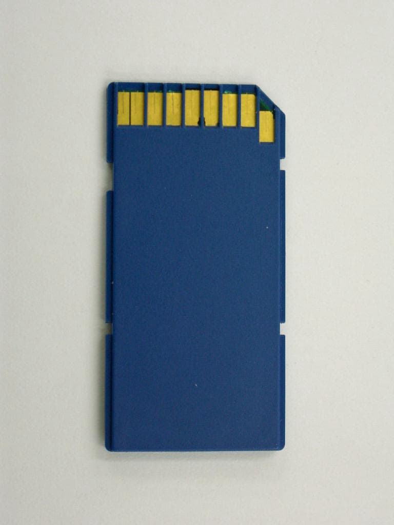
Click to zoom
Application Details
- Equipment Class
- DSS - Part 15 Spread Spectrum Transmitter
- Date of Grant
- Jul 08, 2001
- Application Purpose
- Original Equipment
- Date of Application
- Jul 08, 2001
- Equipment Note
- Bluetooth SD Card
- Frequency Range
- 2402.00000000 - 2480.00000000
- Company
- Dynabook Inc.
- Country
- Japan
Documents & Files
Document Text
Text extracted from the exhibit documents filed with the FCC. Open a document above to read the original.
Users Manual
Confidential Bluetooth™ SD card User's ManualR e v. 1.1 (April 26, 2001) 1 Bluetooth™ SD card User's Manual Rev. 1.2 (May 16, 2001) TOSHIBA CORPORATION Digital Media Network Company Confidential Bluetooth™ SD card User's Manual R ev. 1.1 (April 26, 2001) 2 Revision History RevisionDateComments 1.02001-04-25Initial Revision 1.12001-04-26 Page5: Added Mode name (Palm™Bluetooth™Card) and Model No.(SD-BT00P) for OEM 1.22001-05-16 Page3: Added a sentence in “Feature” section. Confidential Bluetooth™ SD card User's Manual R ev. 1.1 (April 26, 2001) 3 Feature Bluetooth™ SD card is an ultra small and thin card with has built-in antenna and SD/IO interface compliant with SDIO-spec issue by SD Association. Also, as data transmitter/receiver ,CSR’s BlueCore01, which covers Baseband protocol and Link manager protocol, is incorporated into this card to enable any kind of devices which incorporate SDIO-spec SD card slot and the driver software for Bluetooth™ SD card to communicate with each other through this card. Bluetooth™ SD card can be used with any kind of devices which have SDIO card slot and software for Bluetooth SD card, i.e. PDAs, portable PCs, desktop PCs, digital still cameras, cellular phones. Appearance Direction of insertion Indication lamp (green) It ligh ts on dur ing commun ication. Installation When inserting this card into SD card slot, check the form of the connector and insert it surely. PDA supporting the SD/IO Card • Connect the Bluetooth™ SD Card to a PDA. This drawing is an example. As for the position where the Bluetooth™ SD card is connected, refer to the User’s Manual of PDA. Confidential Bluetooth™ SD card User's Manual R ev. 1.1 (April 26, 2001) 4 What you can do with the Bluetooth™ SD Card (1) Mobile communication with cellular phones PDACellular phone (2) Data communication between digital still cameras and PCs Digital still camera PC with Bluetooth Confidential Bluetooth™ SD card User's Manual R ev. 1.1 (April 26, 2001) 5 Specifications Model nameBluetooth TM SD Card *1 Palm™ Bluetooth™ Card *1 Model No.SD-BT00A, SD-BT00U, SD-BT00P *1 Bluetooth™ specification Bluetooth™ Ver.1.0b *2 + critical errata Specification of electric Operating voltage : 3.1 to 3.6V At initializing the card, the voltage of 1.6V to 3.6V is supplied and some parts of SD-IO controller operate. Ripple voltage : 50mVp-p or less RF specificationIn conformity with Bluetooth radio specification Transmission electric power class : Power class 3 [ maximum output : 1mW (0dBm)] Sensitivity of receiving : –70dBm Power management: No Dimension49mm-high x 24mm-wide x 2.1mm-thick A part of protrusion is 2.8mm-thick. Indication function LED : green (It lights during communication.) No light can be selected on by user. *1 : SD-BT00A, SD-BT00U (for Toshiba product) SD-BT00P ( for OEM product ) There is no difference among product with the number in hardware and firmware. *2 : Bluetooth Special Interest Group, Document No. 1.C.47/1.0B, December 1, 1999 Confidential Bluetooth™ SD card User's Manual R ev. 1.1 (April 26, 2001) 6 Ohme, April 25 , 2001 Place, DateSignHiroshi Hamada
Users Manual
Confidential Bluetooth™ SD CARD RF exposure / environment evaluation Rev.1.0 (April 23, 2001) 1 Bluetooth™ SD CARD RF exposure / environmental evalutation Rev. 1.0 (April 23, 2001) TOSHIBA CORPORATION Digital Media Network Company Confidential Bluetooth™ SD CARD RF exposure / environment evaluation Rev.1.0 (April 23, 2001) 2 Revision History RevisionDateComments 1.02001-04-23Initial Revision Confidential Bluetooth™ SD CARD RF exposure / environment evaluation Rev.1.0 (April 23, 2001) 3 USA-Federal Communications Commission(FCC) This device complies with Part 15 of FCC Rules. Operation of the devices in a Bluetooth System is subject to the following two conditions: € This device may not cause harmful interference. € This device must accept any interference that may cause undesired operation. Caution: Exposure to Radio Frequency Radiation. The radiated output power of the Toshiba Bluetooth™ SD Card is far below the FCC radio frequency exposure limits. Nevertheless, the Toshiba Bluetooth™ SD Card shall be used in such a manner that the potential for human contact during normal operation is minimized. When using this device , a certain separation distance between antenna and nearby persons has to be kept to ensure RF exposure compliance. The distance between the antennas and the user should not be less than 5.0cm. Refer to the Regulatory Statements as identified in the documentation that comes with those products for additional information. The Toshiba Bluetooth™ SD Card is far below the FCC radio frequency exposure limits. Nevertheless, it is advised to use the Toshiba Bluetooth™ SD Card in such a manner that human contact during normal operation is minimized. Interference Statement This equipment has been tested and found to comply with the limits for a Class B digital device, pursuant to Part 15 of the FCC Rules. These limits are designed to provide reasonable protection against harmful interference in a residential installation. This equipment generates, uses, and can radiate radio frequency energy. If not installed and used in accordance with the instructions, it may cause harmful interference to radio communications. However, there is no guarantee that interference will not occur in a particular installation. If this equipment does cause harmful interference to radio or television reception, which can be determined by turning the equipment off and on, the user is encouraged to try and correct the interference by one or more of the following measures: € Reorient or relocate the receiving antenna. € Increase the distance between the equipment and the receiver. € Connect the equipment to an outlet on a circuit different from that to which the receiver is connected. € Consult the dealer or an experienced radio/TV technician for help. Toshiba is not responsible for any radio or television interference caused by unauthorized modification of the devices included with this Toshiba Bluetooth™ SD Card, or the substitution or attachment of connecting cables and equipment other than specified by Toshiba . The correction of interference caused by such unauthorized modification, substitution or attachment will be the responsibility of the user.
Cover Letter(s)
TCB RF Exposure Review Procedure Statement FCC ID:CJ6SD00UBT Transmitter Category Device Type Product Category Approval and Review Procedures Used Specific Procedures: VI BlueTooth Wireless Adapter Part 15 Portable Transmitters Section L SP(2), SP(4) with xx=5.0, SP(5), SP(6), SP(7), SP(8), SP(9) and SP(10) Grant Condition: This device and its antenna(s) must operate with a separation distance of at least 5 cm from all persons and must not be co-located or operating in conjunction with any other antenna or transmitter. End-users must be provided with specific operating instructions for satisfying RF exposure compliance . SP2 Max. measured Conducted output power as indicated in page 25 of test report:-2.16dBm@ 2480MHz. Measured power output is within product specification listed in the User Manual Antenna Gain: -2.3dBi. No Cable connection is used with Transmitter..Antenna is self-contained within the Bluetooth Adapter. No other antenna installation willbe required by end users. SP4 RF exposure compliance statement can be found in Exhibit 11 The RF exposurelanguages stated in this document comply with the requirement. SP5 Total 79 channels. Frequency Range : 2402 – 2480 MHz. Which comply with BluetoothCore Specification V 1.0B ( + critical errata). SP6 EUT is not a transmitter module. EUT is equipped with standard PC card connector. It canbe connected to T ype III PC card s lot or two T ype II s tacked PC card s lots . . SP7 No antenna installation is allowed by end user. SP8 User Manual has provided adequate instruction on how to connect the Bluetoothadapter. SP9 TCB has reviewed the Grant conditions and has determined the Grant conditions areapplicable to the device. SP10 By design, 5cm separation distance between LAN adapter to human body can be maintainedby end user . By design , this device can provide at least 2.5cm separation distance fromperson’s hands, wrists, feet and ankles. Reviewed by Mike KuoCompliance Certification ServicesJuly 08, 2001
Cover Letter(s)
-----Ursprüngliche Nachricht----- Von: Mike Kuo [mailto:[email protected]] Gesendet: Freitag, 6. Juli 2001 09:19 An: 'Stabenau Thorsten, Essen' Betreff: RE: Toshiba Blue Tooth pending issues Dear Thorsten: The conversation that I had with Karin is surrending the AC line conducted test for SD Cards. The AC conducted emission plots that you provided were using Peak detector. As the plots indicated, peak emissions are over the QP limits. I mentioned to Karin, Cetecom needs to measure again with QP detector in order to demenstrate compliance. Even though this Blue tooth adapter does not have direct connection to AC main. The required DC power is obtained from PCI slot of Personal Computer. If you read 15.207 requirements carefully, this adapter has to comply with 15.207 requirements. This is the only information that I need from you. After receiving your conducted emission plots with QP detector, I can issue the Grant. Best Regards Mike Kuo From: Silberhorn Karin, Essen [[email protected]] Sent: Wednesday, June 27, 2001 11:48 AM To: 'Mike Kuo' Cc: Stabenau Thorsten, Essen Subject: RE: Toshiba FCC ID:CJ6SD00UBT Assessment no:an01T1329 Importance: High Dear Mike, Here are the answers: 1/ please find attached new internal photographs 2/ please find enclosed the manual, please let me know if it is still unreadable 3/ The SD/IO card is not designed to be connected to the public utility (AC Mains) - it is a plug-in card. The 3.3VDC power supply is provided by the host stack, which from its side has to show compliance for at least Part 15 of the FCC rules (PC, PDA) within a DOC procedure. The Manufacturer of the SD/IO Card is not responsible for the compliance with §15.207 of the host stack §15.207(a) For an intentional radiator which is designed to be connected to the public utility (AC) power line, the radio frequency voltage that is conducted back onto the AC power line on any frequency or frequencies within the band 450 kHz to 30 MHz shall not exceed 250 microvolts. Compliance with this provision shall be based on the meas-urement of the radio frequency voltage between each power line and ground at the power terminals. §15.207(d) Measurements to demonstrate compliance with the conducted limits are not required for devices which only employ battery power for operation and which do not operate from the AC power lines or contain provisions for operation while connected to the AC power lines. Devices that include, or make provisions for, the use of battery chargers which permit operating while charging, AC adapters or battery elimi-nators or that connect to the AC power lines indirectly, obtainig their power through another device which is con-nected to the AC power lines, shall be tested to demonstrate compliance with the conducted limits. However please find enclosed the results for the 15.207 test. In order to proove that the host is responsible for the emissions visible in these plots, we have performed the test once with the host equipment only, the second plot is with the host and the Bluetooth card, the Bluetooth card in transmitting mode. As you can see from the results, the plug-in card does not add any additional emissions, it is the host which is producing all. 4/ this is a mistake, please change the max output power to 0.61mW. Thanks. If you have queries on this e-mail & documents send, please give me a call on my GSM phone. Please let us know when you could issue the grant Thanks in advance for your help Best regards and have a nice day Dipl.-Ing. Karin Silberhorn RC & EMC International Type Approval CETECOM GmbH Im Teelbruch 122 45219 Essen (Germany) Fon: +49 (0) 2054 9519-942 Fax: +49 (0) 2054 9519-964 GSM: +49 (0) 172 204 66 38 e-mail: <mailto:[email protected]> [email protected] home page: www.cetecom. <http://www.cetecom.de/> de -----Original Message----- From: Mike Kuo [ <mailto:[email protected]> mailto:[email protected]] Sent: Wednesday, June 27, 2001 1:38 AM To: '[email protected]' Subject: RE: Toshiba FCC ID:CJ6SD00UBT Assessment no:an01T1329 Dear Karin: What is the status of this application ? Best Regards Mike Kuo -----Original Message----- From: Mike Kuo Sent: Friday, June 15, 2001 7:57 PM To: '[email protected]' Subject: RE: Toshiba FCC ID:CJ6SD00UBT Assessment no:an01T1329 -----Original Message----- From: CERTADM Sent: Friday, June 15, 2001 7:55 PM To: '[email protected]' Cc: Mike Kuo Subject: Toshiba FCC ID:CJ6SD00UBT Assessment no:an01t1329 Notice_content ------------- Question #1: Internal photos are not readable. It should be clear enough to see PCB trace. Please provide another sets of internal photos.( this question is same as question #3 in May, 11 e-mail) Question #2: The user manual that you provided in your e-mail dated 5/24/2001 can not be read. Please check it out. Question #3: Please provide test data per 15.207 requirements. Question #4: The rated RF power output listed in TCB application form is 0.0003W. The Max.measured conducted peak output listed in page 22 of test report is 0.61mW@2480MHz. The typical Class 3 BlueTooth product is specified as max. 1mW output power. Please explain the difference. Best Regards Mike Kuo The items indicated above must be submitted before processing can continue on the above referenced application. Failure to provide the requested information within 60 days of the original e-mail date may result in application dismissal and forfeiture of the filing fee. Also, please note that partial responses increase processing time and should not be submitted. Any questions about the content of this correspondence should be directed to the e-mail address listed below the name of the sender.
External Photos
CETECOM ICT Services GmbH Test report nr..: 2_2488-A/01Issue Date: 05.03.01Page 60 (64) Photographs of the equipment CETECOM ICT Services GmbH Test report nr..: 2_2488-A/01Issue Date: 05.03.01Page 61 (64) Photographs of the equipment
ID Label/Location Info
Confidential Bluetooth™ SD Card Label & Label placement Rev.1.1(April 25, 2001) 1 Bluetooth™ SD card Label & Label placement Rev.1.1(April 25, 2001) TOSHIBA CORPORATION Digital Media Network Company Confidential Bluetooth™ SD Card Label &Label placement Rev.1.1(April 25, 2001) 2 Revision History Revision Date Comments 1.0 2001-04-25 Initial Revision 1.1 2001-04-25 Addition of Label & Label Placement for OEM product on page 5 Confidential Bluetooth™ SD Card Label &Label placement Rev.1.1(April 25, 2001) 3 Contents Label &Label placement for Toshiba standard 4 Label &Label placement for OEM product 5 Confidential Bluetooth™ SD Card Label &Label placement Rev.1.1(April 25, 2001) 4 Label & Label Placement for Toshiba standard bottom view Confidential Bluetooth™ SD Card Label &Label placement Rev.1.1(April 25, 2001) 5 Label & Label placement for OEM product bottom view Confidential Bluetooth™ SD Card Label &Label placement Rev.1.1(April 25, 2001) 6 Ohme, April 25 , 2001 Place, Date Sign Hiroshi Hamada
Internal Photos
CETECOM ICT Services GmbH Test report nr..: 2_2488-A/01Issue Date: 05.03.01Page 62 (64) Photographs of the equipment CETECOM ICT Services GmbH Test report nr..: 2_2488-A/01Issue Date: 05.03.01Page 63 (64) Photographs of the equipment CETECOM ICT Services GmbH Test report nr..: 2_2488-A/01Issue Date: 05.03.01Page 64 (64) Photographs of the equipment
Internal Photos
CJ6SD00UBT Rear PCB view: Front PCB view (shielding on Bluetooth Module): CJ6SD00UBT Front PCB view without shielding on Bluetooth Module:
Test Report
CETECOM ICT Services GmbH Radio Satellite Communication Untertürkheimer Straße 6-10 . D-66117 SaarbrückenTelefon: +49 (0)681 598-9100Telefax: -9075 RSC14issue test report consist of 64 PagesPage 1 (64) Test report no.: 2_2488-A/01 FCC Part 15.247 Bluetooth SD card Accredited Testing Laboratory DAR-Registration number: TTI-P-G 166/98-00 CETECOM ICT Services GmbH Test report nr.:2_2488-A/01Issue date:05.03.01Page 2 (64) Table of Contents 1 General information 1.1 Notes 1.2 Testing laboratory 1.3 Details of applicant 1.4 Application details 1.5 Test item 1.6 Test standards 2 Technical test 2.1 Summary of test results 2.2 Test report 1 General information 1.1 Notes The test results of this test report relate exclusively to the test item specified in 1.5. The CETECOM ICT Services GmbH does not assume responsibility for any conclusions and generalisations drawn from the test results with regard to other specimens or samples of the type of the equipment represented by the test item. The test report may only be reproduced or published in full. Reproduction or publication of extracts from the report requires the prior written approval of the CETECOM ICT Services GmbH. 1.2Testing laboratory CETECOM ICT Services GmbH Untertürkheimer Straße 6 - 10 66117 Saarbrücken Germany Telefone: + 49 681 598 - 9100 Telefax : + 49 681 598 - 9075 E-mail: [email protected] Internet: www.cetecom.de Accredited testing laboratory DAR-registration number : TTI-P-G 166/98-20 CETECOM ICT Services GmbH Test report nr.:2_2488-A/01Issue date:05.03.01Page 3 (64) 1.3Details of applicant Name :TOSHIBA CORPORATION Street :2-9, Suehiro-Cho, Ome City :Tokyo 198-8710 Country :Japan Telephone:+81 428 33 1343 Telefax :+81 428 30 7919 Contact :Mr, Katsuhiro Kinoshita Telephone:+81 428 33 1343 1.4Application details Date of receipt of application : 13.03.01 Date of receipt of test item : 06.04.01 Date of test : 06.04.01 1.5Test item Type of equipment :Radio LAN Type designation:Bluetooth SD card Manufacturer:applicant Street: City: Country: Serial number:-.- Additional informations:: Frequency:2400 – 2483.5 MHz Type of modulation:1M00FXD / 79M8FXD (FHSS) Number of channels :79 Antenna:integral antenna Power supply:3,3V powered by a PC Output power:EIRP: 0,389 mW Type of equipment:Temperature range : 0°C - +55°C 1.6Test standards: FCC Part 15 §15.247 CETECOM ICT Services GmbH Test report nr.:2_2488-A/01Issue date:05.03.01Page 4 (64) 2 Technical test 2.1Summary of test results The radiated measurements were performed verticaly, horizontal results are about 3.5 dB lower over the whole frequency range. The antenna gain measurement was performed by the difference between conducted and radiated output measurement. All measurement settings are according to FCC 15.35, 15.205, 15.209, 15.247 and the „Measurement guidelines for FHSS systems“. No deviations from the technical specification(s) were ascertained in the course of the tests performed. Technical responsibility for area of testing : 17.04.01RSC 8411Berg M. DateSectionNameSignature Technical responsibility for area of testing : 17.04.01RSC8414Ames H. DateSectionNameSignature CETECOM ICT Services GmbH Test report nr.:2_2488-A/01Issue date:05.03.01Page 5 (64) 2.2Testreport TEST REPORT Testreport no. : 2_2488-A/01 CETECOM ICT Services GmbH Test report nr.:2_2488-A/01Issue date:05.03.01Page 6 (64) TEST REPORT REFERENCE LIST OF MEASUREMENTS ParagraphPARAMETER TO BE MEASUREDPAGE Transmitter parameters § 15.204Antenna gain 7 § 15.247 (a) Carrier frequency separation8 § 15.247 (a)Number of hopping channels9 § 15.247 (a)Time of occupancy (dwell time)13 § 15.247 (a)(1)Spectrum bandwidth of a FHSS System18 § 15.247 (b)(2)Maximum peak output power22 §15.247Band edge compliance27 § 15.247 (c)(1)Emission limitations 35 § 15.247 (d) Power spectral density (Inquiry/Page mode)51 Receiver parameters § 15.209Spurious radiations - Radiated52 Test equipment listing56 Photographs of the equipment58 CETECOM ICT Services GmbH Test report nr..: 2_2488-A/01Issue Date: 05.03.01Page 7 (64) Equipment under test : Bluetooth SD card Ambient temperature: 23°C Relative humidity : 31% REFERENCE NUMBER(S) OF TEST EQUIPMENT USED (for reference numbers see test equipment listing) 17-24 - Antenna GainSUBCLAUSE § 15.204 The gain is –2,3 dBi (measured effectiv radiated power over dipol– measured conducted power with a temporary RF- connector) CETECOM ICT Services GmbH Test report nr..: 2_2488-A/01Issue Date: 05.03.01Page 8 (64) Equipment under test : Bluetooth SD card Ambient temperature: 23°C Relative humidity : 31% REFERENCE NUMBER(S) OF TEST EQUIPMENT USED (for reference numbers see test equipment listing) 64 Carrier frequency separation §15.247(a) A UnitdBm -2.5 dB Offset-2.5 dB Offset Ref Lvl -2.5 dBm Ref Lvl -2.5 dBm RF Att 10 dB 500 kHz/Center2.441 GHzSpan5 MHz SWT 5 ms RBW 100 kHz VBW 100 kHz 1MAX1MA -100 -90 -80 -70 -60 -50 -40 -30 -20 -10 1 1 2 Marker 1 [T1] -9.24 dBm 2.44000301 GHz 1 [T1] -9.24 dBm 2.44000301 GHz 1 [T1] 0.26 dB 1.00200401 MHz 2 [T1] -1.25 dB 2.00400802 MHz Date: 6.APR.2001 12:31:01 CETECOM ICT Services GmbH Test report nr..: 2_2488-A/01Issue Date: 05.03.01Page 9 (64) Equipment under test : Bluetooth SD card Ambient temperature: 23°C Relative humidity : 31% REFERENCE NUMBER(S) OF TEST EQUIPMENT USED (for reference numbers see test equipment listing) 64 Number of hopping channels§15.247(a) Channel 1-21 A UnitdBm -2.5 dB Offset-2.5 dB Offset Ref Lvl -2.5 dBm Ref Lvl -2.5 dBm RF Att 10 dB 1MAX1MA SWT 5 ms 2.5 MHz/Start2.4 GHzStop2.425 GHz RBW 300 kHz VBW 300 kHz -100 -90 -80 -70 -60 -50 -40 -30 -20 -10 1 1 Delta 1 [T1] 0.20 dB 20.00000000 MHz 1 [T1] -8.89 dBm 2.40200000 GHz 1 [T1] 0.20 dB 20.00000000 MHz Date: 6.APR.2001 12:34:28 CETECOM ICT Services GmbH Test report nr..: 2_2488-A/01Issue Date: 05.03.01Page 10 (64) Equipment under test : Bluetooth SD card Ambient temperature: 23°C Relative humidity : 31% REFERENCE NUMBER(S) OF TEST EQUIPMENT USED (for reference numbers see test equipme…
Text truncated - open the document above for the full version.
Test Report
CETECOM ICT Services GmbH Radio Satellite Communication Untertürkheimer Straße 6-10 . D-66117 SaarbrückenTelefon: +49 (0)681 598-9100Telefax: -9075 RSC14issue test report consist of 10 PagesPage 1 (10) Test report no.: 2_2488-B/01 FCC Part 15.247 Bluetooth SD card Accredited Testing Laboratory DAR-Registration number: TTI-P-G 166/98-00 CETECOM ICT Services GmbH Test report nr.:2_2488-B/01Issue date:18.04.01Page 2 (10) Table of Contents 1 General information 1.1 Notes 1.2 Testing laboratory 1.3 Details of applicant 1.4 Application details 1.5 Test item 1.6 Test standards 2 Technical test 2.1 Summary of test results 2.2 Test report 1 General information 1.1 Notes The test results of this test report relate exclusively to the test item specified in 1.5. The CETECOM ICT Services GmbH does not assume responsibility for any conclusions and generalisations drawn from the test results with regard to other specimens or samples of the type of the equipment represented by the test item. The test report may only be reproduced or published in full. Reproduction or publication of extracts from the report requires the prior written approval of the CETECOM ICT Services GmbH. 1.2Testing laboratory CETECOM ICT Services GmbH Untertürkheimer Straße 6 - 10 66117 Saarbrücken Germany Telefone: + 49 681 598 - 9100 Telefax : + 49 681 598 - 9075 E-mail: [email protected] Internet: www.cetecom.de Accredited testing laboratory DAR-registration number : TTI-P-G 166/98-20 CETECOM ICT Services GmbH Test report nr.:2_2488-B/01Issue date:18.04.01Page 3 (10) 1.3Details of applicant Name :TOSHIBA CORPORATION Street :2-9, Suehiro-Cho, Ome City :Tokyo 198-8710 Country :Japan Telephone:+81 428 33 1343 Telefax :+81 428 30 7919 Contact :Mr, Katsuhiro Kinoshita Telephone:+81 428 33 1343 1.4Application details Date of receipt of application : 13.03.01 Date of receipt of test item : 06.04.01 Date of test : 06.04.01 1.5Test item Type of equipment :Radio LAN Type designation: Bluetooth SD card Manufacturer:applicant Street: City: Country: Serial number:-.- Additional informations:: Frequency:2400 – 2483.5 MHz Type of modulation:1M00FXD / 79M8FXD (FHSS) Number of channels :79 Antenna:integral antenna Power supply:3,3V powered by a PC Output power:EIRP: 0,389 mW Type of equipment:Temperature range : 0°C - +55°C 1.6Test standards: FCC Part 15 §15.247 CETECOM ICT Services GmbH Test report nr.:2_2488-B/01Issue date:18.04.01Page 4 (10) 2 Technical test 2.1Summary of test results Technical responsibility for area of testing : 18.04.01RSC 8411Berg M. DateSectionNameSignature Technical responsibility for area of testing : 18.04.01RSC8414Ames H. DateSectionNameSignature CETECOM ICT Services GmbH Test report nr.:2_2488-B/01Issue date:18.04.01Page 5 (10) 2.2Testreport TEST REPORT Testreport no. : 2_2488-B/01 CETECOM ICT Services GmbH Test report nr.:2_2488-B/01Issue date:18.04.01Page 6 (10) TEST REPORT REFERENCE LIST OF MEASUREMENTS ParagraphPARAMETER TO BE MEASUREDPAGE Transmitter parameters § 15.247 (f)Processing gain 7 CETECOM ICT Services GmbH Test report nr.:2_2488-B/01Issue date:18.04.01Page 7 (10) Introduction This report describes the results of the processing gain measurement for the Toshiba Bluetooth SD card using the FCC CW jamming margin method. Requirement Hybrid systems that employ a combination of both direct sequence and frequency hopping modulation techniques shall achieve a processing gain of at least 17 dB from the combined technique. System losses In the formula for calculation the processing gain appears the term system losses. In Bluetooth there are two major causes for the system loss: 1. The non optimal sampling time. The CW jamming method assures that the optimal sampling time as determined before, in fact, as described above, it will be determined via the access code. 2. Losses due to attenuation in the RF part. Although this two points produce a system loss which will be much greater than 2 dB, we calculated with this value, because this is the maximum that will be accepted by FCC. CETECOM ICT Services GmbH Test report nr.:2_2488-B/01Issue date:18.04.01Page 8 (10) Test setup: Device under test 6 dB Coupler 6 dB Coupler Fixed Attenuator Signaling device RF Switch Step Attenuator Power Amplifier Spectrum Analyser Signal Generator High Pass Noise Source To set-up the connection a special test program was used. It is installed on the laptop and communicates with the Toshiba Bluetooth SD card. The BER was determined with a special test software over 1600000 Bits . Measurement Results : S/N Measurement : The measurement for S/N was performed by adding noise to the wanted signal. The noise level was adjusted until the BER reached 0.1 %. With this measurement configuration the S/N ratio was 7.8 dB. CETECOM ICT Services GmbH Test report nr.:2_2488-B/01Issue date:18.04.01Page 9 (10) The jammer signal was stepped in 50 kHz steps over the receiving channel. For every step the jammer level was adjusted until the BER was 0.1 %. The ratio between wanted signal power and the jammer power at the RF input of the device is the required Jammer to Signal ratio. With this measurement configuration the JSR has the following results: Jammer Offset(KHz) Jammer-SignalJammer/Signal ratio BER -500-63.614.40.1% -450-63.814.60.1% -400-63.814.60.1% -350-62.813.60.1% -300-61.912.70.1% -250-60.311.10.1% -200-58.29.00.1% -150-55.26.70.1% -100-52.63.40.1% -50-50.91.70.1% 0-51.01.80.1% +50-51.52.30.1% +100-55.05.80.1% +150-58.08.80.1% +200-60.110.90.1% +250-61.912.70.1% +300-62.313.10.1% +350-63.214.00.1% +400-63.314.10.1% +450-63.414.20.1% +500-63.013.80.1% Wanted signal : -49.2 dBm Signal/Noise : -7.8 dBm CETECOM ICT Services GmbH Test report nr.:2_2488-B/01Issue date:18.04.01Page 10 (10) Disregarding the marked data points –500, -450, -400, +400, +450 kHz) the worst data point is at –400 / -450 kHz with a Jammer / Signal value of 14.6 dB. Processing gain calculation With these values the processing gain for the DSS part of the system i…
Text truncated - open the document above for the full version.
Test Setup Photos
CETECOM ICT Services GmbH Test report nr..: 2_2488-A/01Issue Date: 05.03.01Page 58 (64) Test site
Contact Information
Applicant
Ryuichi Kamimura(Senior Manager)
Test Firm
CETECOM GmbHWolfgang Richter
Technical Specifications
| # | Rule Parts | Frequency Range | Power Output |
|---|---|---|---|
| 1 | 15C | 2.40 GHz - 2.48 GHz | 610.00 µW |
Other Applications from Dynabook Inc.

CJ6PA5347RT
Oct 20, 2022dynabook Wireless Optical Silent Mouse
Equipment Class
DXX - Part 15 Low Power Communication Device Transmitter
CJ6PYT0XPC
Apr 28, 2021Notebook Computer
Equipment Class
DSS - Part 15 Spread Spectrum Transmitter
CJ6UPA5238WL
Sep 01, 2015dynadock WiAC
Equipment Class
NII - Unlicensed National Information Infrastructure TX
CJ6UPA5144TJ
Aug 07, 2014TransferJet USB Adapter
Equipment Class
JBP - Part 15 Class B Computing Device Peripheral
CJ6UPA5145TJ
Aug 07, 2014TransferJet MicroUSB Adapter
Equipment Class
UWB - Ultra Wideband Transmitter