CJ6UPA3272WLToshiba Wireless LAN Card
Dynabook Inc.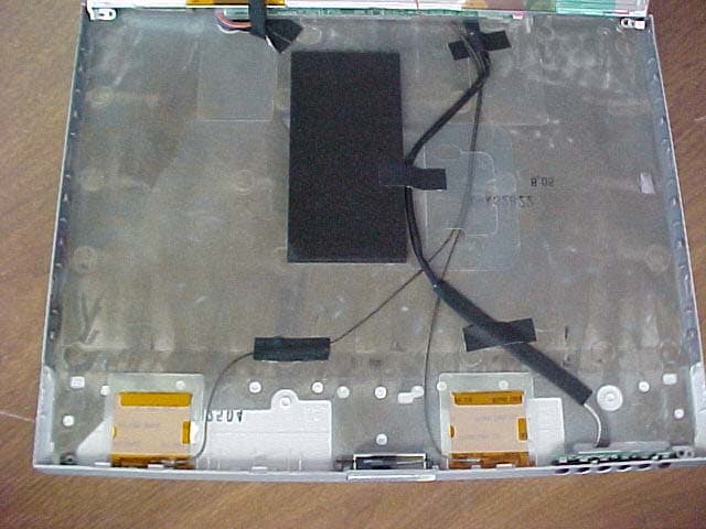
Click to zoom
Application Details
- Equipment Class
- DTS - Digital Transmission System
- Date of Grant
- Dec 30, 2002
- Application Purpose
- Original Equipment
- Date of Application
- Dec 30, 2002
- Equipment Note
- Toshiba Wireless LAN Card
- Frequency Range
- 2412.00000000 - 2462.00000000
- Company
- Dynabook Inc.
- Country
- Japan
Documents & Files
Document Text
Text extracted from the exhibit documents filed with the FCC. Open a document above to read the original.
Users Manual
This sheet is for information only. The wireless LAN card must be installed by Toshiba or Toshiba OEM dealers. 2. Apply to following Wireless LAN label to position C shown in the figure for the Tecra 9000 or the figure for the Portégé 4000. Apply this Label
Cover Letter(s)
Toshiba Corporation FCC ID: CJ6UPA3272WL Request for transmitter modular approval Transmitter Module Characteristics Item Requirements EUT 1 Have its own RF shielding Device is equipped with Metal shielding to cover RF section. Refer to Page internal photos 2 Have buffered modulation/data inputs (if such inputs are provided), All inputs to the modules are buffered through logic or microprocessor inputs. 3 Have it own power supply regulation Internal power regulator. Refer to Block diagram 4 Meet the antenna requirements of Section 15.203 Device is equipped with unique antenna ( u.FL(v)- LP-040/u.FL-LP-062) connector. Refer to page photos 5 Be tested in a stand-alone configuration, i.e., the antenna, AC or DC power and data input/output lines must be connected to the module but, the module must not be inside another case during testing Device was tested outside the host computer as stand-alone configuration. Refer to setup photos. 6 Be labeled with its own FCC ID number, and if the FCC ID is not visible when the module is installed inside another device, then the outside of the device into which the module is installed must also display a label referring to the enclosed module. Two proposed FCC ID label format are included in the filing. One of label is to be placed on the module and the other label is to be placed on the outside of system. Refer to FCC ID label format and location file. 7 Address compliance with the Commission's RF exposure limits in Sections 1.1310 and 2.1093. In addition, spread spectrum transmitters operating under Section 15.247 are required to address RF exposure compliance in accordance with Section 15.247(b)(4). The max. output power measured is below the low threshold. SAR evaluation is exempted. Antenna will be installed to provide at least 20cm separation distance to the body.
Cover Letter(s)
December 20, 2002 American TCB 6731 Whittier Ave., Suite C110 McLean, VA 22101 Gentlemen: The attached documentation is provided in support of a formal submission to your organization for FCC certification of an intentional unlicensed transmitter. On behalf of our client, Aegis Labs has included an application for a Grant of Equipment Authorization pursuant to Subpart C of part 15 of FCC Rules (47 CFR) regarding intentional radiators. The data within the test report demonstrates the equipment was tested in a manner described under Part 2 and 15 of the Code of Federal Regulations. Aegis Labs, Inc. prepared this submittal as an authorized agent. A copy of the letter of our appointment as agent is enclosed. If there are any additional questions or if further information is needed, please contact us at your earliest convenience. Sincerely, Steve Kuiper Aegis Labs, Inc. Quality Assurance Manager Enclosure (1 Emissions Test Report + Exhibits) AEGIS LABS, INC 22431 Antonio Parkway B160-417, Rancho Santa Margarita, CA 92688 949-459-7886 TEL 949-459-7869 FAX www.aegislabsinc.com
Cover Letter(s)
1 dward From: Rick [[email protected]] Sent: Tuesday, March 25, 2003 10:23 AM To: [email protected] Subject: RE: audit Antenna - Dual Film Data Sheet... Antenna - Dual Film Drawing.pd... Antenna - Ethertronics Generic. Antenna - Ethertronics Specifi.. Antenna - Hitachi Cable Loss M... Antenna - Hitachi specs.pdf (2... Antenna - Wide Dual Film Data.... Antenna - Wide Dual Film Drawi... Photograph - Antenna Location ... Photographs - Test Setup.pdf (... Request for Modular approval.p.. Dennis, Please see the response below. 1) Please give summary list and description of antenna options contained in this filing. Answer: The antennas for this filling are as follows: Hitachi Antenna, Ethertronics Antenna, Toshiba Dual Film Antenna, and Toshiba Wide Dual Film Antenna. Please refer to "Antenna" attachments for the descriptions. 2) Grant note has no-co-loc statement, exhibit "Antenna Location" seems to show diversity and co-loc antennas - please explain. Answer: The Grant note is correct. The photograph I provided with the original submitall was incorrect. Please refer to "Photograph - Antenna Location" attachment. 3) Filing contains two EMC reports - 142 pages and 187 pages. Why two separate reports, what are differences? Answer: There is only suppose to be one EMC test report. The 142 page report is the correct one. 4) Please submit separate exhibit(s) for Test Setup Photos containing only photos, not complete EMC report. Please include close-up photos of typical stand-alone setup for radiated tests. Answer: Please refer to "Photographs - Test Setup" attachment. 5) DA 00-1407 has eight numbered criteria, cover letter here only lists seven - please revise. Answer: Please refer to "Request for Modular Approval" attachment. If there is anything else that you need, please let me know. Regards, Rick Candelas Aegis Labs, Inc. Tel. 949.459.7886 Fax 949.459-7869 Mobile 949.456-0130 E-Mail: [email protected]
Cover Letter(s)
Toshiba Corporation FCC ID: CJ6UPA3272WL Limited Modular Approval Item Requirements EUT 1 Have its own RF shielding Device is equipped with Metal shielding to cover RF section. Refer to Page internal photos 2 Have buffered modulation/data inputs (if such inputs are provided), All inputs to the modules are buffered through logic or microprocessor inputs. 3 Have it own power supply regulation Internal power regulator. Refer to Block diagram 4 Meet the antenna requirements of Section 15.203 Device is equipped with unique antenna ( u.FL(v)-LP-040/u.FL-LP- 062) connector. Refer to page photos 5 Be tested in a stand-alone configuration, i.e., the antenna, AC or DC power and data input/output lines must be connected to the module but, the module must not be inside another case during testing Device was tested outside the host computer as stand-alone configuration. Refer to setup photos. 6 Be labeled with its own FCC ID number, and if the FCC ID is not visible when the module is installed inside another device, then the outside of the device into which the module is installed must also display a label referring to the enclosed module. Two proposed FCC ID label format are included in the filing. One of label is to be placed on the module and the other label is to be placed on the outside of system. Refer to FCC ID label format and location file. 7 The user cannot influence the operation of the transmitter that will operate outside of the scope of the regulations. The modular transmitter is restricted to Toshiba laptops and will only be installed by authorized personnel so that the user cannot influence the operation of the transmitter that will operate outside of the scope of the regulations. (Refer to “User’s Guide Exhibit) 8 Address compliance with the Commission's RF exposure limits in Sections 1.1310 and 2.1093. In addition, spread spectrum transmitters operating under Section 15.247 are required to address RF exposure compliance in accordance with Section 15.247(b)(4). The max. output power measured is below the low threshold. SAR evaluation is exempted. Antenna will be installed to provide at least 20cm separation distance to the body.
External Photos
FCC ID: PD9WM3B2100 Top View “Hitachi Antennas” FCC ID: PD9WM3B2100 Bottom View “Hitachi Antennas” FCC ID: PD9WM3B2100 Cable Length Between Antenna and Device “Hitachi Antennas” 20 inch coax cable FCC ID: PD9WM3B2100 Top View “Ethetronics Antennas” FCC ID: PD9WM3B2100 Bottom View “Ethertronics Antennas” FCC ID: PD9WM3B2100 Cable Length Between Antenna and Device “Ethertronics Antennas” 20 inch coax cable
External Photos
View Transmitter Inside the Portege Laptop
External Photos
●Portage4000 133mm 91mm
ID Label/Location Info
TOSHIBA MoW SINGLE BAND MPCI 3B A/W# C2482901 P/N C24829-001 This Class B digital apparatus meets all requirements of the Canadian Interference-Causing equipment Regulations. CANADA ICES/NMB-003 Class/Classe (B) CANADA: 248H-DPA3272W 03NYDA0041 03GZDA0036 2.4DS4 CE mark applicable only with Intel authorized antenna solutions 03NYDA0041 03GZDA0036 2.4DS4 BARCODE AREA This Class B digital apparatus meets all requirements of the Canadian Interference-Causing equipment Regulations. CANADA ICES/NMB-003 Class/Classe (B) CANADA: 248H-DPA3272W TOSHIBA MoW SINGLE BAND MPCI 3B MASTER VERSION P/N Cxxxxx-001 MTC: xxxxxxxx CNC: xx-xxxx SUBTEL: xxxxx SCT: xxxxxxxx-xxx Instytut Lacznosci Potw. zgodn. Nr. xxx/xxxx xxxxxx-xxxxxxx AG/UM-xxxx.xxx B.xx.TK.x.xx.xx.xx/xxxx-xxxx BARCODE AREA FOR HOME OR OFFICE USE Tested to Comply with FCC Standards FCC ID: CJ6UPA3272WL This device is only authorized for use as instructed by Intel. P/C: WM3B2100WWTOS Approved by IDA for use in Singapore. DBxxxxx Model: WM3B2100 P/N: PA3272U-1MPC TRE-xxx/xxxx/xxxx-xx-xxxx xxxxxxxx CMII ID: xxxxxxxxxx MALAYSIA FOR HOME OR OFFICE USE Tested to Comply with FCC Standards FCC ID: CJ6UPA3272WL This device is only authorized for use as instructed by Intel. P/C: WM3B2100WWTOS Approved by IDA for use in Singapore. DB02941 Model: WM3B2100 P/N: PA3272U-1MPC CE mark applicable only with Intel authorized antenna solutions E178682 CUS E178682 CUS
ID Label/Location Info
Bottom side view Regulatory Label Regulatory Label of Wireless LAN on bottom of PC
Internal Photos
●Portage4000 40mm 93mm 91mm
Internal Photos
FCC ID: PD9WM3B2100 Top View “Insulation removed” FCC ID: PD9WM3B2100 Bottom View “Insulation removed” FCC ID: PD9WM3B2100 Top View “Shielding removed” FCC ID: PD9WM3B2100 Top View “Insulation Added” FCC ID: PD9WM3B2100 Bottom View “Insulation Added”
Operational Description
Wireless LAN This appendix describes Wireless LAN features and TOSHIBA Wireless LAN card specifications. For details on Wireless LAN settings, refer to the LAN Card Settings and Client Manager help file. These references have the latest information. About Toshiba Wireless Solution The Wireless LAN Card Kit enables you to: Connect your computer to a peer-to-peer workgroup of wireless computing devices. Connect your computer to a Local Area Network (LAN) Infrastructure that includes Wireless LAN Access Points, or other IEEE802.11 compliant LAN systems. Expand the capabilities of your Wireless LAN Access Points, to support wireless devices that have been equipped with Wireless LAN Card. NOTE:The internal Wireless LAN Card can’t be used with the “Toshiba Wireless LAN PC Card”. Peer-to-Peer Workgroup The Peer-to-Peer workgroup configuration enables you to quickly set up a small wireless workgroup, where the workgroup participants can exchange files using features such as Files and Printer Sharing as supported by Microsoft Networking. Figure 1-1 Peer-to-Peer Wireless Workgroup You can use this option to setup a temporary or ad-hoc network in environments where no access points are available, for example in Small Office/Home Office (SOHO) environments. As long as the stations are within range of one another, this is the easiest and least expensive way to set up a wireless network. Enterprise Networking Figure 1-2 Stand Alone Wireless LAN With the Wireless LAN Access Points you can connect to a corporate Local Area Network (LAN) infrastructure to have wireless access to all network facilities. LAN Infrastructures may either be. Stand-alone wireless LANs as pictures in Figure 1-2 Wireless network infrastructures connected to an existing Ethernet network as pictured in Figure 1-3. Figure 1-3 LAN Infrastructure Configuration The Wireless LAN Card functions like any standard wired Ethernet card except it gives you the freedom of Wireless connections. Where an Ethernet card requires a cable connection to a hub and/or patch panel, the cable physically limits the location of the wired connection. A Wireless LAN allows you connect your computer to a Local Area Network (LAN) from anywhere within the Wireless coverage area. NOTE: The Wireless LAN Card is a radio product. Refer to the flyer Information to the User for regulatory information that may apply in your country/region. Wireless LAN Card Features Toshiba Wireless LAN mini-PCI Card is a wireless network card that fits into a Mini-PCI TypeIII slot. Wireless LAN Card Types The Wireless LAN Card is a wireless network card that complies with the IEEE 802.11 standard on wireless LANs supports data rates up to 11 Mbit/s. Wi-Fi (Wireless Fidelity) certified by the Wireless Ethernet Compatibility Alliance (WECA). This means that your Wireless hardware will communicate with other vendors’ IEEE 802.11 compliant wireless LAN product. Fully compatible with any other wireless LAN system based on Direct Sequence Spread Spectrum (DSSS) radio technology that complies with the “IEEE 802.11 standard on wireless LANs Revision B. Wireless LAN Cards The Wireless LAN Card supports the following wireless LAN features: Automatic Transmit Rate Select mechanism in the transmit range of 11, 5.5, 2 and 1 Mbit/s. Frequency Channel Selection. Roaming over multiple channels. Card Power Management. Wired Equivalent Privacy (WEP) data encryption, based on 128bit encryption algorithm. Card Specifications Form Factor - Mini PCI TypeIII Capability - IEEE 802.11 Standard for Wireless LANS (DSSS) Wi-Fi (Wireless Fidelity) certified by the Wireless Ethernet Compatibility Alliance (WECA) Network Operating - Microsoft Windows® Networking System Media Access Protocol - CSMA/CA (Collision Avoidance) with Acknowledgment (ACK) Data Rate - 11/5.5/2/1 Mb/s (Revision B) Radio Characteristics Radio Characteristics of Wireless LAN Cards may vary according to: country/region where the product was purchased Type of product Wireless communication is often subject to local radio regulations. Although Wireless LAN Wireless networking products have been designed for operation in the license-free 2.4GHz band, local radio regulations may impose a number of limitations to the use of wireless communication equipment. NOTE: Refer to the flyer "Information to the User” for regulatory information that may apply in your country/region. R-F Frequency -Band2.4GHz (2400-2483.5 MHz) Modulation Technique Direct Sequence Spread Spectrum -CCK, DQPSK, DBPSK The range of the wireless signal is related to the Transmit Rate of the wireless communication. Communications at lower Transmit range may travel larger distances. The range of your wireless devices can be affected when the antennas are placed near metal surfaces and solid high-density materials. Range is also impacted due to “obstacles” in the signal path of the radio that may either absorb or reflect the radio signal. Supported Frequency Sub-bands Subject to the radio regulations that apply in your country, your Wireless LAN Card may support a different set of 2.4 GHz channels Consult your Authorized Wireless LAN or TOSHIBA Sales office for information about the radio regulations that apply in your country/region. Wireless IEEE 802.11 Channels Sets (Revision B) Frequency Range 2400-2483.5 MHz Channel ID 1 2412 2 2417 3 2422 4 2427 5 2432 6 2437 7 2442 8 2447 9 2452 10 2457* 11 2462 * Factory-set default channels When installing Wireless LAN Cards, the channel configuration is managed as follows: For wireless clients that operate in a Wireless LAN Infrastructure, the Wireless LAN Card will automatically start operation at the channel identified by the Wireless LAN Access Point, When roaming between different access points the station can dynamically switch to another channel if required. For Wireless LAN Cards installed in Wireless clients that operating in a peer-to-peer mode, the card will use the default channel 10. In a Wir…
Text truncated - open the document above for the full version.
Operational Description
1 Information sheet Wireless Interoperability The Intel(R) PRO/Wireless LAN 2100 3B Mini PCI Adapter products are designed to be interoperable with any wireless LAN product that is based on Direct Sequence Spread Spectrum (DSSS) radio technology, and is compliant to: ■ The IEEE 802.11 Standard on Wireless LANs (Revision B), as defined and approved by the Institute of Electrical and Electronics Engineers. ■ The Wireless Fidelity (Wi-Fi) certification as defined by the WECA Wireless Ethernet Compatibility Alliance. CAUTION Bluetooth™ and WirelessLAN devices operate within the same radio frequency range and may interfere with one another. If you use Bluetooth™ and WirelessLAN devices simultaneously, you may occasionally experience a less than optimal network performance or even lose your network connection. If you should experience any such problem, immediately turn off either one of your Bluetooth™ or WirelessLAN. Please contact Toshiba PC product support on web site http://www.toshiba-europe.com/computers/tnt/bluetooth.htm in Europe or http://www.pc.support.global.toshiba.com in the United States for more information. Wireless LAN and your Health Wireless LAN products, like other radio devices, emit radio frequency electromagnetic energy. The level of energy emitted by Wireless LAN devices however is far much less than the electromagnetic energy emitted by wireless devices like for example mobile phones. Because Wireless LAN products operate within the guidelines found in radio frequency safety standards and recommendations, TOSHIBA believes Wireless LAN is safe for use by consumers. These standards and recommendations reflect the consensus of the scientific community and result from deliberations of panels and committees of scientists who continually review and interpret the extensive research literature. In some situations or environments, the use of Wireless LAN may be restricted by the proprietor of the building or responsible representatives of the organization. These situations may for example include: ■ Using the Wireless LAN equipment on board of airplanes, or ■ In any other environment where the risk of interference to other devices or services is perceived or identified as harmful. If you are uncertain of the policy that applies on the use of wireless devices in a specific organization or environment (e.g. airports), you are encouraged to ask for authorization to use the Wireless LAN device prior to turning on the equipment. Regulatory Information The Intel(R) PRO/Wireless LAN 2100 3B Mini PCI Adapter must be installed and used in strict accordance with the manufacturer’s instructions as described in the user documentation that comes with the product. This device complies with the following radio frequency and safety standards. Canada – Industry Canada (IC) 2 This device complies with RSS 210 of Industry Canada. Operation is subject to the following two conditions: (1) this device may not cause interference, and (2) this device must accept any interference, including interference that may cause undesired operation of this device.” L ‘ utilisation de ce dispositif est autorisée seulement aux conditions suivantes : (1) il ne doit pas produire de brouillage et (2) l’ utilisateur du dispositif doit étre prêt à accepter tout brouillage radioélectrique reçu, même si ce brouillage est susceptible de compromettre le fonctionnement du dispositif. The term "IC" before the equipment certification number only signifies that the Industry Canada technical specifications were met. IC : 248H-DPA3272W This device has been designed to operate with an antenna having a maximum gain of 4.8dB. Antenna having a higher gain is strictly prohibited per regulations of Industry Canada. The required antenna impedance is 50 ohms. To reduce potential radio interference to other users, the antenna type and its gain should be so chosen that the equivalent isotropically radiated power (EIRP) is not more than that required for successful communication. To prevent radio interference to the licensed service, this device is intended to be operated indoors and away from windows to provide maximum shielding. Equipment (or its transmit antenna) that is installed outdoors is subject to licensing. Pour empecher que cet appareil cause du brouillage au service faisant l'objet d'une licence, il doit etre utilize a l'interieur et devrait etre place loin des fenetres afin de Fournier un ecram de blindage maximal. Si le matriel (ou son antenne d'emission) est installe a l'exterieur, il doit faire l'objet d'une licence. Europe – EU Declaration of Conformity This device complies with the essential requirements of the R&TTE Directive 1999/5/EC with essential test suites as per standards: ■ EN 60950 Safety of Information Technology equipment ■ ETS 300 328 Technical requirements for radio equipment ■ ETS 300 826 General EMC requirements for radio equipment. For outdoor usage only channel 10 (2457 MHz) and 11 (2462 MHz) is allowed. For private usage outside buildings across public grounds over less than 300m no special registration with IBPT/BIPT is required. Registration to IBPT/BIPT is required for private usage outside buildings across public grounds over more than 300m. An IBPT/BIPT license is required for public usage outside building. For registration and license please contact IBPT/BIPT. Gebruik buiten gebouw alleen op kanalen 10 (2457 MHz) en 11 (2462 MHz). Voor privé-gebruik buiten gebouw over publieke groud over afstand kleiner dan 300m geen registratie bij BIPT/IBPT nodig; voor gebruik over afstand groter dan 300m is wel registratie bij BIPT/IBPT nodig. Voor publiek gebruik buiten gebouwen is licentie van BIPT/IBPT verplicht. Voor registratie of licentie kunt u contact opnemen met BIPT. België/ Belgique: L’utilisation en extérieur est autorisé sur le canal 10 (2457 MHz) et 11 (2462 MHz). Dans le cas d’une utilisation privée, à l’extérieur d’un bâtiment, au-dessus d’un espace public, aucun enregistrement n’est nécessaire p…
Text truncated - open the document above for the full version.
Operational Description
Toshiba Dual Film Antenna Data Sheet Model Name Day Plane X-Y Frequency 2.441 Data File LCD Degree 90 Data No. Position Antenna Cable <Antenna Gain> Horizontal Vertical AVG-4.7 -1.8 MAX 0.5 0.6 (dBi) Coaxial Cable 0.8φ 510mm Comment In put 0dBm Sine Wave from SG Wireless LAN Main (Right) SuzkaCS08Dual011210 #9,10 0°:Front 90°:Right 11/28/01 Suzuka with Dualband Film Antenna Hor Ver 0° 270° (dBi) -10 0 -20 -30 90°
Operational Description
The GY model, part of the TrueNet™ Family of WLAN Internal Antennas from Ethertronics, represents a new category of small form factor, internal (embedded) antennas for WLAN multi-band applications. Multi-band capability allows OEMs to migrate their existing product designs by offering a single multi-mode antenna that supports both 802.11a/b protocols. In addition, the GY model offers up to twice the range and greater isolation properties compared to existing internal antenna solutions. Ethertronics’ proprietary and patented antenna technology offers three distinct advantages over traditional internal antennas: High Performance • High efficiency • Average of 30-50% higher signal strength than other internal antennas Shaping Technology • Controls and redirects the near-field electromagnetic distribution of the antenna’s wave • Optimizes antenna performance by improving signal strength and data quality inside buildings, in noisy environments and in fringe network coverage areas • Less interaction with surrounding objects High Isolation/Selectivity • Ideal for diversity applications • Reduced EMI with surrounding components • Makes integration easy The GY antenna is ideally suited for wireless data devices, where performance, size and system costs are critical. The surface mount design and compact size are suited for high volume applications. Standard antenna profiles are available or can be configured to suit individual OEM requirements. Advantages: WLAN 9605 Scranton Road, Suite 850 tel +(1) 858.550.3820 San Diego, CA 92121 • U.S.A. fax +(1) 858.550.3821 www.ethertronics.com [email protected] Ethertronics Applications: PC/mini-PCI Cards • PDAs Laptops Multi-Band Capability • Single internal antenna covers several WLAN frequency bands saving cost and valuable PCB space Spatial Diversity • Antenna elements can be placed in close proximity to each other with reduced risk of coupling from one to another Better Performance • Increased range/rate • Improved sensitivity in low signal environments Flexible Integration • Minimal component keep-out areas • Smaller product size and ground plane requirements • Reduction in front end components and matching circuits WLAN Technologies: 802.11a/b/g HomeRF • HyperLAN/2 • WiFi GY Internal Antenna 16.0 x 8.0 x 2.5 mm DualNet 2.4/5.2/5.8 GHz WLAN Internal Antenna TM © 2002 Ethertronics. All rights reserved. The Ethertronics logo is a registered trademark; TrueNet, DualNet and shaping antenna technology are trademarks of Ethertronics. All other trademarks are the property of their respective owners. 083002 2.400-2.485/5.150-5.350/5.725-5.825 GHz Internal (Embedded) Antenna Specifications Model: GY 2.400-2.485 GHz 5.150-5.350 GHz Peak Gain 2 dBi 5 dBi Efficiency 80 % 75 % VSW R Match 2 : 1 2 : 1 Front to Back Ratio 3 dB 10 dB Feed Point Impedance 50 ohms unbalanced (other if required) Power Handling 2 W att cw Polarization Linear Shielding Ratio 6 to 1 (near field) 5.725-5.825 GHz 5 dBi 75 % 2 : 1 10 dB Typical Return Loss: Size 16.0 x 8.0 x 2.5 mm, other configurations available Mounting Surface mount, 1 connection point + 1 feeding point Weight 1 gram Packaging Tape and reel, tray optional Electrical Specifications: Antenna Radiation Patterns: 2.400-2.485 GHz Band 5.150-5.825 GHz Band E-plane ( xz ) Main-pol Cross-pol Mechanical Specifications: 2 dBi -8 dBi -18 dBi 5 dBi -5 dBi -15 dBi 5 dBi -5 dBi -15 dBi 2.533.544.555.56 -20 -18 -16 -14 -12 -10 -8 -6 -4 -2 0 (dB) Frequency (GHz) H-plane ( yz ) Specifications subject to change without notice. x z x z y z y z 2 dBi -8 dBi -18 dBi Typical Characteristics (Inside an enclosure)
Operational Description
Page 1 Ethertronics Ethertronics Antenna Performance Antenna Performance Verification Verification Intel Corporation Intel Corporation Mobile Communications Division Mobile Communications Division San Diego, CA San Diego, CA 13 September 2002 13 September 2002 Page 2 [email protected] Measurements Measurements y y 10 Units (2 antennas per unit) 10 Units (2 antennas per unit) – – Return Loss / VSWR Return Loss / VSWR y y Antenna Patterns Antenna Patterns – – 1 unit (SN4) 1 unit (SN4) – – Measured on Intel Certification Vehicle Measured on Intel Certification Vehicle Page 3 [email protected] Gain Measurements Gain Measurements y y Positive gain values Positive gain values y y Good coverage Good coverage Ethertronics Diversity Test Results SN4Main A uxiliary Azimuth Azimuth Polarization Max Min Ave Max Min A ve Polarizatio n Max Min A ve Max Min A ve Vert 0.53 -9.78 -4.96 -4.12 -20.48 -12.80 Vert 0.78 -17.92 -5.96 -3.73 -22.79 -12.59 Horiz -7.65 -27.19 -13.28 -0.53 -17.85 -5.72 Horiz 1.88 -23.58 -8.16 0.49 -24.21 -10.00 PolSel 0.54 -9.30 -4.72 -0.53 -10.33 -4.31 PolSel 1.91 -11.85 -3.70 0.49 -17.73 -7.71 Elevation 1 Elevation 1 Polarization Max Min Ave Max Min A ve Polarizatio n Max Min A ve Max Min A ve Vert 0.87 -27.40 -8.00 0.96 -27.07 -10.49 Vert 1.83 -25.19 -8.71 2.02 -25.72 -10.03 Horiz 1.18 -20.91 -7.84 -4.31 -29.65 -15.48 Horiz 0.42 -19.86 -6.56 -3.68 -25.72 -12.74 PolSel 1.18 -11.36 -3.96 0.97 -21.96 -8.89 PolSel 2.14 -13.46 -4.28 2.05 -20.14 -7.90 Elevation 2 Elevation 2 Polarization Max Min Ave Max Min A ve Polarizatio n Max Min A ve Max Min A ve Vert 0.00 -23.25 -8.95 -6.40 -28.92 -15.29 Vert -1.00 -22.82 -9.32 -6.47 -23.66 -13.97 Horiz -8.93 -24.94 -15.23 -0.01 -26.88 -9.34 Horiz -7.27 -32.47 -17.30 0.00 -27.86 -9.53 PolSel 0.00 -18.12 -8.06 -0.01 -24.34 -8.49 PolSel -0.98 -17.21 -8.93 0.04 -21.45 -8.08 802.1B 802.11A 802.1B 802.11A 802.1B 802.11A 802.1B 802.11A 802.1B 802.11A 802.1B 802.11A Page 4 [email protected] Antenna Patterns Antenna Patterns – – Azimuth Plane Azimuth Plane Polarization Select -35-30-25-20-15-10 -5 05 0 5 10 15 20 25 30 35 40 45 50 55 60 65 70 75 80 85 90 95 100 105 110 115 120 125 130 135 140 145 150 155 160 165 170 175 180 185 190 195 200 205 210 215 220 225 230 235 240 245 250 255 260 265 270 275 280 285 290 295 300 305 310 315 320 325 330 335 340 345 350 355 360 520053005800 Polarization Select -35-30-25-20-15-10 -5 05 0 5 10 15 20 25 30 35 40 45 50 55 60 65 70 75 80 85 90 95 100 105 110 115 120 125 130 135 140 145 150 155 160 165 170 175 180 185 190 195 200 205 210 215 220 225 230 235 240 245 250 255 260 265 270 275 280 285 290 295 300 305 310 315 320 325 330 335 340 345 350 355 360 240024502500 802.11B 802.11A Page 5 [email protected] Polarization Select -35-30-25-20-15-10 -5 05 0 5 10 15 20 25 30 35 40 45 50 55 60 65 70 75 80 85 90 95 100 105 110 115 120 125 130 135 140 145 150 155 160 165 170 175 180 185 190 195 200 205 210 215 220 225 230 235 240 245 250 255 260 265 270 275 280 285 290 295 300 305 310 315 320 325 330 335 340 345 350 355 360 520053005800 Polarization Select -35-30-25-20-15-10 -5 05 0 5 10 15 20 25 30 35 40 45 50 55 60 65 70 75 80 85 90 95 100 105 110 115 120 125 130 135 140 145 150 155 160 165 170 175 180 185 190 195 200 205 210 215 220 225 230 235 240 245 250 255 260 265 270 275 280 285 290 295 300 305 310 315 320 325 330 335 340 345 350 355 360 240024502500 Antenna Patterns Antenna Patterns – – Elevation 1 Plane Elevation 1 Plane 802.11B 802.11A Page 6 [email protected] Polarization Select -35-30-25-20-15-10 -5 05 0 5 10 15 20 25 30 35 40 45 50 55 60 65 70 75 80 85 90 95 100 105 110 115 120 125 130 135 140 145 150 155 160 165 170 175 180 185 190 195 200 205 210 215 220 225 230 235 240 245 250 255 260 265 270 275 280 285 290 295 300 305 310 315 320 325 330 335 340 345 350 355 360 520053005800 Polarization Select -35-30-25-20-15-10 -5 05 0 5 10 15 20 25 30 35 40 45 50 55 60 65 70 75 80 85 90 95 100 105 110 115 120 125 130 135 140 145 150 155 160 165 170 175 180 185 190 195 200 205 210 215 220 225 230 235 240 245 250 255 260 265 270 275 280 285 290 295 300 305 310 315 320 325 330 335 340 345 350 355 360 240024502500 Antenna Patterns Antenna Patterns – – Elevation 2 Plane Elevation 2 Plane 802.11B 802.11A
Operational Description
Reference Antenna Kit for Intel ® PRO/Wireless LAN Mini-PCI Adapters The Intel ® PRO/Wireless LAN Mini-PCI adapter (models: 5000, 7100 and 2100) requires an …
Text truncated - open the document above for the full version.
Contact Information
Applicant
Ryuichi Kamimura(Senior Manager)
Technical Contact
Aegis Labs, IncSteve Kuiper
[email protected]949 459 7886
22431-B160 Antonio Parkway #417 · Rancho Santa Margarita, California · United States
Test Firm
Aegis Labs, Inc.Rick Candelas
Technical Specifications
| # | Rule Parts | Frequency Range | Power Output |
|---|---|---|---|
| 1 | 15C | 2.41 GHz - 2.46 GHz | 47.00 mW |
Other Applications from Dynabook Inc.

CJ6PA5347RT
Oct 20, 2022dynabook Wireless Optical Silent Mouse
Equipment Class
DXX - Part 15 Low Power Communication Device Transmitter
CJ6PYT0XPC
Apr 28, 2021Notebook Computer
Equipment Class
DSS - Part 15 Spread Spectrum Transmitter
CJ6UPA5238WL
Sep 01, 2015dynadock WiAC
Equipment Class
NII - Unlicensed National Information Infrastructure TX
CJ6UPA5144TJ
Aug 07, 2014TransferJet USB Adapter
Equipment Class
JBP - Part 15 Class B Computing Device Peripheral
CJ6UPA5145TJ
Aug 07, 2014TransferJet MicroUSB Adapter
Equipment Class
UWB - Ultra Wideband Transmitter