CJ6UPA3299WLP802.11 b/g Mini-PCI Module in Tablet PC
Dynabook Inc.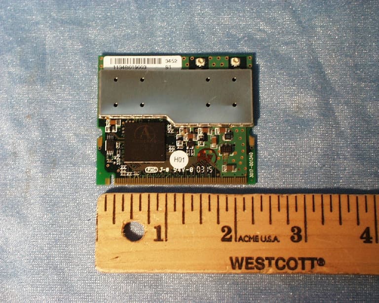
Click to zoom
Application Details
- Equipment Class
- DTS - Digital Transmission System
- Date of Grant
- Nov 12, 2003
- Application Purpose
- Original Equipment
- Date of Application
- Nov 12, 2003
- Equipment Note
- 802.11 b/g Mini-PCI Module in Tablet PC
- Frequency Range
- 2412.00000000 - 2462.00000000
- Company
- Dynabook Inc.
- Country
- Japan
Documents & Files
Document Text
Text extracted from the exhibit documents filed with the FCC. Open a document above to read the original.
Users Manual
1 Wireless LAN Card Features The Wireless LAN Card is a wireless network card that fits into a Mini-PCI TypeIII slot. Wireless LAN Card Types The Wireless LAN Card is a wireless network card that complies with the IEEE 802.11 standard on wireless LANs (Revision B, G). Revision G supports data rates up to 54 Mbit/s. Revision B supports data rates up to 11 Mbit/s. Wi-Fi (Wireless Fidelity) certified by the Wi-Fi Alliance. This means that your Wireless hardware will communicate with other vendors’ IEEE 802.11 compliant wireless LAN product. The 'Wi-Fi CERTIFIED' logo is a certification mark of the Wi-Fi Alliance. Fully compatible with any other wireless LAN system based on Direct Sequence Spread Spectrum (DSSS)/ Orthogonal Frequency Division Multiplexing (OFDM) radio technology that complies with the “IEEE 802.11 standard on wireless LANs (Revision B or G). Wireless LAN Cards The Wireless LAN Card supports the following wireless LAN features: Automatic Transmit Rate Select mechanism in the transmit range of 54,48,36,24,18,12, 9 and 6 Mbit/s. (Revision G) Automatic Transmit Rate Select mechanism in the transmit range of 11, 5.5, 2 and 1 Mbit/s. (Revision B) Frequency Channel Selection (2.4GHz:Revision B, G). Roaming over multiple channels. Card Power Management. Wired Equivalent Privacy (WEP) data encryption, based on 152bit encryption algorithm. Advanced Encryption Standard (AES) data encryption, based on 256bit encryption algorithm. Card Specifications Form Factor - Mini PCI TypeIII Capability - IEEE 802.11 Standard for Wireless LANS Wi-Fi (Wireless Fidelity) certified by the Wi-Fi Alliance. Network Operating - Microsoft Windows® Networking System Media Access Protocol - CSMA/CA (Collision Avoidance) with Acknowledgment (ACK) Data Rate - 54/48/36/24/18/12/9/6 Mb/s (Revision G) - 11/5.5/2/1 Mb/s (Revision B) Radio Characteristics Radio Characteristics of Wireless LAN Cards may vary according to: country/region where the product was purchased Type of product Wireless communication is often subject to local radio regulations. Although Wireless LAN Wireless networking products have been designed for operation in the license-free 2.4GHz band, local radio regulations may impose a number of limitations to the use of wireless communication equipment. 2 NOTE: Refer to the flyer "Information to the User” for regulatory information that may apply in your country/region. R-F Frequency -Band2.4GHz (2400-2483.5 MHz) (Revision B, G) Modulation Technique -DSSS-CCK, DSSS-DQPSK, DSSS-DBPSK (Revision B) -OFDM-BPSK, OFDM-QPSK, OFDM-16QAM, OFDM-64QAM (Revision G,) The range of the wireless signal is related to the Transmit Rate of the wireless communication. Communications at lower Transmit range may travel larger distances. The range of your wireless devices can be affected when the antennas are placed near metal surfaces and solid high-density materials. Range is also impacted due to “obstacles” in the signal path of the radio that may either absorb or reflect the radio signal. Supported Frequency Sub-bands Subject to the radio regulations that apply in your country, your Wireless LAN Card may support a different set of 2.4GHz channels. Consult your Authorized Wireless LAN or TOSHIBA Sales office for information about the radio regulations that apply in your country/region. Wireless IEEE 802.11 Channels Sets (Revision B, G) Frequency Range Channel ID 2400-2472 MHz 1 2412 2 2417 3 2422 4 2427 5 2432 6 2437 7 2442 8 2447 9 2452 10 2457* *1) 11 2462 *1) Factory-set default channels When installing Wireless LAN Cards, the channel configuration is managed as follows: For wireless clients that operate in a Wireless LAN Infrastructure, the Wireless LAN Card will automatically start operation at the channel identified by the Wireless LAN Access Point, when roaming between different access points the station can dynamically switch to another channel if required. For Wireless LAN Cards installed in Wireless clients that operating in a peer-to-peer mode, the card will use the default channel 10. In a Wireless LAN Access Point, the Wireless LAN card will use the factory-set default channel (printed in bold), unless the LAN Administrator selected a different channel when configuring the Wireless LAN Access Point device. 3 Information sheet Wireless Interoperability The Atheros AR5001X+ Wireless Network Adapter products are designed to be interoperable with any wireless LAN product that is based on Direct Sequence Spread Spectrum (DSSS) /Orthogonal Frequency Division Multiplexing(OFDM) radio technology, and is compliant to: The IEEE 802.11 Standard on Wireless LANs(Revision B/G), as defined and approved by the Institute of Electrical and Electronics Engineers. The Wireless Fidelity(Wi-Fi) certification as defined by the Wi-Fi Alliance. The “Wi-Fi CERTIFIED” logo is a certification mark of the Wi-Fi Alliance. CAUTION Bluetooth™ and WirelessLAN devices operate within the same radio frequency range and may interfere with one another. If you use Bluetooth™ and WirelessLAN devices simultaneously, you may occasionally experience a less than optimal network performance or even lose your network connection. If you should experience any such problem, immediately turn off either one of your Bluetooth™ or WirelessLAN. Please contact Toshiba PC product support on web site http://www.toshiba-europe.com/computers/tnt/bluetooth.htm in Europe or http://www.pc.support.global.toshiba.comin the United States for more information. Wireless LAN and your Health Wireless LAN products, like other radio devices, emit radio frequency electromagnetic energy. The level of energy emitted by Wireless LAN devices however is far much less than the electromagnetic energy emitted by wireless devices like for example mobile phones. Because Wireless LAN products operate within the guidelines found in radio frequency safety standards and recommendations, TOSHIBA believes Wireless LAN is safe for use by consumers. These standar…
Text truncated - open the document above for the full version.
Users Manual
AR5001 Client Utility HelpAR5001 Client Utility HelpPA3299U-1MPC Wireless LAN Card FeaturesWireless LAN Card Features...........................................................................................2 Card SpecificationsCard Specifications.......................................................................................................3 IntroductionIntroduction......................................................................................................................5 System RequirementsSystem Requirements...................................................................................................5 Package ContentsPackage Contents.........................................................................................................5 Profile ManagementProfile Management.........................................................................................................6 Add a New or Modify a Configuration ProfileAdd a New or Modify a Configuration Profile..............................................................6 Ad Hoc Mode Profile ConfigurationAd Hoc Mode Profile Configuration..............................................................................8 Access Point Mode Profile ConfigurationAccess Point Mode Profile Configuration.....................................................................8 Remove a Configuration ProfileRemove a Configuration Profile...................................................................................10 TCP/IP ConfiguratioTCP/IP Configurationn..................................................................................................10 Profile ManagementProfile Management.....................................................................................................11 Zero ConfigurationZero Configuration.......................................................................................................11 Security TabSecurity Tab.....................................................................................................................13 Define PreDefine Pre--Shared Encryption KeysShared Encryption Keys............................................................................13 Check the Status Information or DiagnosticsCheck the Status Information or Diagnostics.................................................................15 Current StatusCurrent Status.............................................................................................................15 Driver Information ButtonDriver Information Button..........................................................................................16 DiagnosticsDiagnostics...................................................................................................................16 Profile Management: Available APs and Ad Hoc Networks ListProfile Management: Available APs and Ad Hoc Networks List....................................17 Action MenuAction Menu....................................................................................................................19 Country Code SelectorCountry Code Selector.................................................................................................19 Tray IconTray Icon..........................................................................................................................21 Display SettingsDisplay Settings..............................................................................................................22 Updating the NDIS DriverUpdating the NDIS Driver..............................................................................................23 Information sheetInformation sheet............................................................................................................24 Wireless LAN Card Features The Wireless LAN Card is a wireless network card that fits into a Mini-PCI TypeIII slot. Wireless LAWireless LAN Card TypesN Card Types The Wireless LAN Card is a wireless network card that complies with the IEEE 802.11 standard on wireless LANs (Revision B, G), Turbo Mode. Revision G supports data rates up to 54 Mbit/s. Revision B supports data rates up to 11 Mbit/s. Turbo Mode supports data rates up to 108 Mbit/s. n Wi-Fi (Wireless Fidelity) certified by the Wi-Fi Alliance. This means that your Wireless hardware will communicate with other vendors’ IEEE 802.11 compliant wireless LAN product. The 'Wi-Fi CERTIFIED' logo is a certification mark of the Wi-Fi Alliance. n Fully compatible with any other wireless LAN system based on Direct Sequence Spread Spectrum (DSSS)/ Orthogonal Frequency Division Multiplexing (OFDM) radio technology that complies with the “IEEE 802.11 standard on wireless LANs (Revision B or G). Wireless LAN CaWireless LAN Cardsrds The Wireless LAN Card supports the following wireless LAN features: n Automatic Transmit Rate Select mechanism in the transmit range of 54,48,36,24,18,12, 9 and 6 Mbit/s. (Revision G) n Automatic Transmit Rate Select mechanism in the transmit range of 11, 5.5, 2 and 1 Mbit/s. (Revision B) n Automatic Transmit Rate Select mechanism in the transmit range of 108,96,72,48,36, 24,18 and 12 Mbit/s. (Turbo Mode) n Frequency Channel Selection (2.4GHz:Revision B, G). n Roaming over multiple channels. n Card Power Management. n Wired Equivalent Privacy (WEP) data encryption, based on 152bit encryption algorithm. n Advanced Encryption Standard (AES) data encryption, based on 256bit encryption algorithm. Card Specifications Form Factor - Mini PCI TypeIII Capability - IEEE 802.11 Standard for Wireless LANS Wi-Fi (Wireless Fidelity) certified by the Wi-Fi Alliance. Network Operating - Microsoft Windows® Networking System Media Access Protocol - CSMA/CA (Collision Avoidance) with Acknowledgment (ACK) Data Rate - 54/48/36/24/18/12/9/6 Mb/s (Revision G) - 11/5.5/2/1 Mb/s (Revision B) - 108/96/72/48/36/24/18/12 Mb/s (Turbo Mode) Radio Radio CharacteristicsCharacteristics Radio Characteristics of…
Text truncated - open the document above for the full version.
Users Manual
TOSHIBA Portégé M200 Portable Personal Computer User’s Manual Copyright © 2003 by TOSHIBA Corporation. All rights reserved. Under the copyright laws, this manual cannot be reproduced in any form without the prior written permission of TOSHIBA. No patent liability is assumed, with respect to the use of the informa- tion contained herein. TOSHIBA Portégé M200 Portable Personal Computer User’s Manual First edition November 2003 Disclaimer This manual has been validated and reviewed for accuracy. The instructions and descriptions it contains are accurate for the TOSHIBA Portégé M200 Portable Personal Computer at the time of this manual’s production. However, succeeding computers and manuals are subject to change without notice. TOSHIBA assumes no liability for damages incurred directly or indirectly from errors, omissions or discrepancies between the computer and the manual. Trademarks IBM is a registered trademark of International Business Machines Corporation. Intel, Pentium and Centrino are registered trademarks and SpeedStep is a trademark of Intel Corporation. Windows and Microsoft are registered trademarks of Microsoft Corporation. Bluetooth is a trademark owned by its proprietor and used by TOSHIBA under licence. Other trademarks and registered trademarks not listed above may be used in this manual. FCC information Product Name : Portégé M200 Model number : PPM20 FCC notice "Declaration of Conformity Information" This equipment has been tested and found to comply with the limits for a Class B digital device, pursuant to part 15 of the FCC rules. These limits are designed to provide reasonable protection against harmful interference in a residential installa- tion. This equipment generates, uses and can radiate radio frequency energy and, if not installed and used in accordance with the instructions, may cause harmful interference to radio communications. However, there is no guarantee that interfer- ence will not occur in a particular installation. If this equipment does cause harmful interference to radio or television reception, which can be determined by turning the equipment off and on, the user is encouraged to try to correct the interference by one or more of the following measures: ❑Reorient or relocate the receiving antenna. ❑Increase the separation between the equipment and receiver. ❑Connect the equipment into an outlet on a circuit different from that to which the receiver is connected. ❑Consult the dealer or an experienced radio/TV technician for help. WARNING: Only peripherals complying with the FCC class B limits may be attached to this equipment. Operation with non-compliant peripher- als or peripherals not recommended by TOSHIBA is likely to result in interference to radio and TV reception. Shielded cables must be used between the external devices and the computer’s external monitor port, USB port and microphone jack. Changes or modifications made to this equipment, not expressly approved by TOSHIBA or parties authorized by TOSHIBA could void the user’s authority to operate the equipment. The modular cable that comes with the computer must be used to connect a modem. FCC conditions This device complies with part 15 of the FCC Rules. Operation is subject to the following two conditions: 1. This device may not cause harmful interference. 2. This device must accept any interference received, including interference that may cause undesired operation. Contact Address:TOSHIBA America Information Systems, Inc. 9740 Irvine Boulevard Irvine, California 92618-1697 Telephone:(949) 583-3000 EU Declaration of Conformity TOSHIBA declares, that the product: PPM20* conforms to the following Standards: Supplementary Information:“The product complies with the requirements of the Low Voltage Directive 73/23/EEC, the EMC Directive 89/336/EEC and/or the R&TTE Directive 1999/05/EEC.” This product is carrying the CE-Mark in accordance with the related European Directives. Responsible for CE-Marking is TOSHIBA Europe, Hammfelddamm 8, 41460 Neuss, Germany. VCCI Class B Information Modem warning notice Conformity Statement The equipment has been approved to [Commission Decision “CTR21”] for pan- European single terminal connection to the Public Switched Telephone Network (PSTN). However, due to differences between the individual PSTNs provided in different countries/regions the approval does not, of itself, give an unconditional assurance of successful operation on every PSTN network termination point. In the event of problems, you should contact your equipment supplier in the first instance. Network Compatibility Statement This product is designed to work with, and is compatible with the following networks. It has been tested to and found to conform with the additional require- ments conditional in EG 201 121. GermanyATAAB AN005,AN006,AN007,AN009,AN010 and DE03,04,05,08,09,12,14,17 GreeceATAAB AN005,AN006 and GR01,02,03,04 PortugalATAAB AN001,005,006,007,011 and P03,04,08,10 SpainATAAB AN005,007,012, and ES01 SwitzerlandATAAB AN002 All other countries/regionsATAAB AN003,004 Specific switch settings or software setup are required for each network, please refer to the relevant sections of the user guide for more details. The hookflash (timed break register recall) function is subject to separate national type approvals. It has not been tested for conformity to national type regulations, and no guarantee of successful operation of that specific function on specific national networks can be given. Japan regulations Region selection If you are using the computer in Japan, technical regulations described in the Telecommunications Business Law require that you select the Japan region mode. It is illegal to use the modem in Japan with any other selection. Redial Up to two redial attempts can be made. If more than two redial attempts are made, the modem will return Black Listed. If you are experiencing problems with the Black Listed code, set the interval between redials at one minute or longer. Japan’…
Text truncated - open the document above for the full version.
Cover Letter(s)
DIGITAL MEDIA NETWORK COMPANY OME COMPLEX 2-9, SUEHIRO-CHO, OME, TOKYO 198-8710, JAPAN PHONE: +81(428) 34-1872 FAX: +81(428) 33-2922 October 16, 2003 Federal Communications Commission Authorization and Evaluation Division 7435 Oakland Mills Road Columbia, MD 21046 Re: Request for Confidentiality In reference to the application under FCC ID: CJ6UPA3299WLP, and pursuant to Sections 0.457(d)(1)(ii) and 0.459 of the Commission's Rules, the Applicant hereby requests confidential treatment of the accompanying information as outlined below: Schematics Block diagram Theory of operation The above materials contain trade secrets and proprietary information not customarily released to the public. The public disclosure of these matters might be harmful to the Applicant and provide unjustified benefits to its competitors. The Applicant understands that pursuant to Rule 0.457(d)(1)(ii), disclosure of this Application and all accompanying documentation will not be made before the date of the Grant for this application. Sincerely, Hideo Abe Digital Media Network Company
Cover Letter(s)
Toshiba Corporation FCC ID: CJ6UPA3299WLP Request for transmitter modular approval Transmitter Module Characteristics Item Requirements EUT 1 Have its own RF shielding Device is equipped with Metal shielding to cover RF section. Refer to external photos 2 Have buffered modulation/data inputs (if such inputs are provided), All inputs to the modules are buffered through logic or microprocessor inputs. 3 Have it own power supply regulation Internal 1.8V power regulator. Refer to Block diagram 4 Meet the antenna requirements of Section 15.203 Device is equipped with unique antenna ( u.FL(v)- LP-040) connector. Refer to external photos 5 Be tested in a stand-alone configuration, i.e., the antenna, AC or DC power and data input/output lines must be connected to the module but, the module must not be inside another case during testing Device was tested inside the laptop for limited modular approval. Refer to setup photos. 6 Be labeled with its own FCC ID number, and if the FCC ID is not visible when the module is installed inside another device, then the outside of the device into which the module is installed must also display a label referring to the enclosed module. Two proposed FCC ID label format are included in the filing. One of label is to be placed on the module and the other label is to be placed on the outside of system. Refer to FCC ID label format and location file. 7 The modular transmitter is manufactured so that the user cannot influence the operation of the transmitter that will operate outside of the scope of the regulations. Refer to “User’s Guide” Exhibit 8 Address compliance with the Commission's RF exposure limits in Sections 1.1310 and 2.1093. In addition, spread spectrum transmitters operating under Section 15.247 are required to address RF exposure compliance in accordance with Section 15.247(b)(4). SAR test was performed on the portable laptop, Portege M200 (model No: PPM20U-AAAA2).
Cover Letter(s)
1 Mike Kuo From: Claire Hoque Sent: November122003Wednesday 11:29 AM To: Mike Kuo Cc: Steve Cheng; Michael Conrad; Michael Heckrotte; Sunny Shih Subject: RE: Toshiba FCC ID:CJ6UPA3299WLP, AN03T3373 Hi Mike, Here are the answers for Toshiba 03U2196. Question #1: The BT antenna gain listed in the EMC test report is different than the value listed in the SAR test report. Please explain. <MH>The higher gain numbers are for the antenna itself; the lower gain numbers are for the antenna assembly including the integrated coaxial cable. All reports are revised to consistently report assembly gains. Question #2: Please indicate which WLAN antenna was selected during EMC and SAR tests. <MH>Testing was performed with the highest gain antennas. Attached report 03U2196-1 has been revised to clarify all the antenna model numbers and their applications. 03U2196-1 FCC DTS Report(revi... <Sunny>Please refer to attached updated SAR report to updated antenna gain information. 03U2196-2 SAR 2.4GHz Test Repo... Question #3: Page 1-1 of user manual indicates the modular cable will be supplied with notebook computer. However, there is no description on such modular cable. Please explain the usage of this modular cable. <Toshiba>The modular cable mentioned is the telephone cord with RJ11 plugs used with the internal modem in the PC, and has nothing to do with the modules. Question #4:Please address SAR test mode to justify the SAR evaluation documented in this filing can provide justification for RF exposure compliance based upon the device usage as illustrated in page 4-10 of user manual. <Sunny>Please refer to attached illustration "Toshiba Reply to Question #4.pdf" for the answer. Toshiba Reply to Question #4.p... Thanks, Claire Hoque Compliance Certification Services 561F Montery Road Morgan Hill, CA 95037 Tel: (408) 463-0885 x 123 Fax: (408) 463-0888
ID Label/Location Info
Bottom side view Regulatory Label of Wireless LAN on bottom of PC Regulatory Label Regulatory Label on Mini PCI Wireless LAN Card MAC Address Label Label with P/N and Country of Origin Serial Number Label Label with P/N and Country of Origin MAC Address Label Serial Number Label
Parts List/Tune Up Info
Toshiba PC Internal Antenna Data 1. Model Name HTL008-P*** 2. Frequency Range 2.4 – 2.5 GHz , 5.15 5.85GHz 3. Bandwidth 2.4GHz : Over 200MHz ( VSWR :under 2 ) 5GHz : Over 900MHz 4. Gain (Average) Antenna fixed on the LCD of Tecra9000 (Measure at Toshiba EMI Site) X-Y PLANE (dBi) Antenna Horizontal Vertical 2.441GHz -4.7 -1.8 5.350GHz -4.6 -4.2 5. Antenna position LCD Wireless LAN Sub Bluetooth Wireless LAN Main 5. VSWR Antenna attached on the Package of Tecra9000 Wireless LAN Main Antenna 6. Radiation Pattern Please refer to ToshibaDualbandFilmAntennaData.xls file. The azimuth of graph drawn in xls file is bellow. 7. Polarization Vertical 8. Impedance 50Ù 0° 90° 270° 180°
Parts List/Tune Up Info
Toshiba PC Internal Antenna Data 1. Model Name HTL004-P*** 2. Frequency Range 2.4 – 2.5 GHz 3. Bandwidth Over 200MHz ( VSWR :under 2 ) 4. Gain (Average) Antenna fixed on the LCD of Satellite1850 (Measure at Toshiba EMI Site) X-Y PLANE (dBi) Antenna Horizontal Vertical 2.442GHz -4.5 -3.8 5. Antenna position LCD Wireless LAN Sub Bluetooth Wireless LAN Main 5. VSWR Antenna attached on the Package of Satellite 1850 Bluetooth Antenna 6. Radiation Pattern Please refer to “HTL004AntennaData.xls” file. The azimuth of graph drawn in xls file is bellow. 7. Polarization Vertical 8. Impedance 50 0 90 270 180
Parts List/Tune Up Info
Toshiba PC Internal Antenna Data 1. Model Name HTL012-P*** 2. Frequency Range 2.4 – 2.5 GHz , 5.15 5.85GHz 3. Bandwidth 2.4GHz : Over 200MHz ( VSWR :under 2 ) 5GHz : Over 900MHz( VSWR :under 2 ) 4. Gain (Average) Antenna fixed on the LCD of Tecra9000 (Measure at Toshiba EMI Site) X-Y PLANE (dBi) Antenna Horizontal Vertical 2.441GHz -3.5 -0.7 5.350GHz -10.0 -6.3 5. Antenna position LCD Wireless LAN Sub Bluetooth Wireless LAN Main 5. VSWR Antenna attached on the Package of Tecra9000 Wireless LAN Main Antenna 6. Radiation Pattern Please refer to “HTL012AntennaData.xls” file. The azimuth of graph drawn in xls file is bellow. 7. Polarization Vertical 8. Impedance 50Ù 0° 90° 270° 180°
RF Exposure Info
20cm away from body At least 1.5cm away from body during normal operation Hand Touched, 20cm away from body 1.5 cm away from Arm, 20cm from body
RF Exposure Info
in accordance with the requirements of FCC Report and Order: ET Docket 93-62, and OET Bulletin 65 Supplement C for 802.11b/g Mini PCI Module Model: PA3299U-1MPC FCC ID: CJ6UPA3299WLP October 6, 2003 REPORT NO: 03U2196-2 Prepared for Toshiba Corporation Digital Media Network Company Ome Complex, 2-9, Suehiro-cho, Ome Tokyo, 198-8710, Japan Prepared by COMPLIANCE CERTIFICATION SERVICES 561F MONTEREY ROAD MORGAN HILL, CA 95037 USA TEL: (408) 463-0885 REPORT NO: 03U2196-2 DATE: October 6, 2003 FCC ID: CJ6UPA3299WLP COMPLIANCE CERTIFICATION SERVICES Page: 2 of 25 This report shall not be reproduced except in full, without the written approval of CCS. This document may be altered or revised by Compliance Certification Services personnel only, and shall be noted in the revision section of the document. CERTIFICATE OF COMPLIANCE (SAR EVALUATION) Dates of Tests: October 6, 2003 APPLICANT: Toshiba Corporation Digital Media Network Company 2-9, Suehiro-cho, Ome Complex Tokyo, 198-8710, Japan MODEL: PA3299U-1MPC FCC ID: CJ6UPA3299WLP DEVICE CATEGORY: PORTABLE DEVICES EXPOSURE CATEGORY: GENERAL POPULATION/UNCONTROLLED EXPOSURE Test Sample is a: Production unit Modulation type: 802.11b Direct Sequence Spread Spectrum (DSSS) 802.11g Orthogonal Frequency Division Multiplexing (OFDM) Tx Frequency: 2412 MHz to 2462 MHz Max. O/P Power: (Conducted/Peak) 802.11b: 17dBm 802.11g: 21.03dBm Max. SAR (1g): 802.11b: 0.367mW/g 802.11b: 0.380mW/g (Co-location) 802.11g: 0.355mW/g Application Type: Certification FCC Rule Part(s): §15.247 This wireless portable device has been shown to be capable of compliance for localized specific absorption rate (SAR) for uncontrolled environment/general population exposure limits specified in ANSI/IEEE Std. C95.1-1992 and had been tested in accordance with the measurement procedures specified in FCC OET 65 Supplement C (released on 6/29/2001 see Test Report). I attest to the accuracy of data. All measurements reported herein were performed by me or were made under my supervision and are correct to the best of my knowledge and belief. I assume full responsibility for the completeness of these measurements and vouch for the qualifications of all persons taking them. Steve Cheng EMC Engineering Manager REPORT NO: 03U2196-2 DATE: October 6, 2003 FCC ID: CJ6UPA3299WLP COMPLIANCE CERTIFICATION SERVICES Page: 3 of 25 This report shall not be reproduced except in full, without the written approval of CCS. This document may be altered or revised by Compliance Certification Services personnel only, and shall be noted in the revision section of the document. TABLE OF CONTENTS 1. EUT DESCRIPTION .................................................................................................................4 2. REQUIREMENTS FOR COMPLIANCE TESTING DEFINED BY THE FCC ....................................5 3. DOSIMETRIC ASSESSMENT SYSTEM ......................................................................................5 3.1. MEASUREMENT SYSTEM DIAGRAM.....................................................................................................6 3.2. SYSTEM COMPONENTS......................................................................................................................7 DASY4 MEASUREMENT SERVER.........................................................................................7 DATA ACQUISITION ELECTRONICS (DAE)..............................................................................7 ET3DV6 ISOTROPIC E-FIELD PROBE FOR DOSIMETRIC MEASUREMENTS...............................7 SAM PHANTOM (V4.0)........................................................................................................8 DEVICE HOLDER FOR SAM TWIN PHANTOM..........................................................................8 SYSTEM VALIDATION KITS....................................................................................................8 4. EVALUATION PROCEDURES ...................................................................................................9 5. MEASUREMENT UNCERTAINTY .............................................................................................12 6. EXPOSURE LIMIT ..................................................................................................................13 7. MEASUREMENT RESULTS ....................................................................................................14 7.1. SYSTEM PERFORMANCE CHECK.......................................................................................................14 7.2. TEST LIQUID CONFIRMATION.............................................................................................................15 7.3. EUT TUNE-UP PROCEDURES.....…
Text truncated - open the document above for the full version.
Contact Information
Applicant
Ryuichi Kamimura(Senior Manager)
Test Firm
Compliance Certification Services IncSteve Cheng
Technical Specifications
| # | Rule Parts | Frequency Range | Power Output |
|---|---|---|---|
| 1 | 15C | 2.41 GHz - 2.46 GHz | 120.00 mW |
Other Applications from Dynabook Inc.

CJ6PA5347RT
Oct 20, 2022dynabook Wireless Optical Silent Mouse
Equipment Class
DXX - Part 15 Low Power Communication Device Transmitter
CJ6PYT0XPC
Apr 28, 2021Notebook Computer
Equipment Class
DSS - Part 15 Spread Spectrum Transmitter
CJ6UPA5238WL
Sep 01, 2015dynadock WiAC
Equipment Class
NII - Unlicensed National Information Infrastructure TX
CJ6UPA5144TJ
Aug 07, 2014TransferJet USB Adapter
Equipment Class
JBP - Part 15 Class B Computing Device Peripheral
CJ6UPA5145TJ
Aug 07, 2014TransferJet MicroUSB Adapter
Equipment Class
UWB - Ultra Wideband Transmitter