CJ6UPA3362WL802.11 b/g Mini-PCI Card.
Dynabook Inc.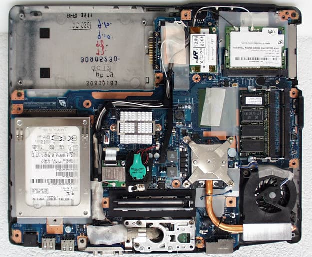
Click to zoom
Application Details
- Equipment Class
- DTS - Digital Transmission System
- Date of Grant
- Jan 05, 2004
- Application Purpose
- Original Equipment
- Date of Application
- Jan 05, 2004
- Equipment Note
- 802.11 b/g Mini-PCI Card.
- Frequency Range
- 2412.00000000 - 2462.00000000
- Company
- Dynabook Inc.
- Country
- Japan
Documents & Files
Document Text
Text extracted from the exhibit documents filed with the FCC. Open a document above to read the original.
Users Manual
TOSHIBA Portégé M200 Portable Personal Computer User’s Manual Copyright © 2003 by TOSHIBA Corporation. All rights reserved. Under the copyright laws, this manual cannot be reproduced in any form without the prior written permission of TOSHIBA. No patent liability is assumed, with respect to the use of the informa- tion contained herein. TOSHIBA Portégé M200 Portable Personal Computer User’s Manual First edition November 2003 Disclaimer This manual has been validated and reviewed for accuracy. The instructions and descriptions it contains are accurate for the TOSHIBA Portégé M200 Portable Personal Computer at the time of this manual’s production. However, succeeding computers and manuals are subject to change without notice. TOSHIBA assumes no liability for damages incurred directly or indirectly from errors, omissions or discrepancies between the computer and the manual. Trademarks IBM is a registered trademark of International Business Machines Corporation. Intel, Pentium and Centrino are registered trademarks and SpeedStep is a trademark of Intel Corporation. Windows and Microsoft are registered trademarks of Microsoft Corporation. Bluetooth is a trademark owned by its proprietor and used by TOSHIBA under licence. Other trademarks and registered trademarks not listed above may be used in this manual. FCC information Product Name : Portégé M200 Model number : PPM20 FCC notice "Declaration of Conformity Information" This equipment has been tested and found to comply with the limits for a Class B digital device, pursuant to part 15 of the FCC rules. These limits are designed to provide reasonable protection against harmful interference in a residential installa- tion. This equipment generates, uses and can radiate radio frequency energy and, if not installed and used in accordance with the instructions, may cause harmful interference to radio communications. However, there is no guarantee that interfer- ence will not occur in a particular installation. If this equipment does cause harmful interference to radio or television reception, which can be determined by turning the equipment off and on, the user is encouraged to try to correct the interference by one or more of the following measures: ❑Reorient or relocate the receiving antenna. ❑Increase the separation between the equipment and receiver. ❑Connect the equipment into an outlet on a circuit different from that to which the receiver is connected. ❑Consult the dealer or an experienced radio/TV technician for help. WARNING: Only peripherals complying with the FCC class B limits may be attached to this equipment. Operation with non-compliant peripher- als or peripherals not recommended by TOSHIBA is likely to result in interference to radio and TV reception. Shielded cables must be used between the external devices and the computer’s external monitor port, USB port and microphone jack. Changes or modifications made to this equipment, not expressly approved by TOSHIBA or parties authorized by TOSHIBA could void the user’s authority to operate the equipment. The modular cable that comes with the computer must be used to connect a modem. FCC conditions This device complies with part 15 of the FCC Rules. Operation is subject to the following two conditions: 1. This device may not cause harmful interference. 2. This device must accept any interference received, including interference that may cause undesired operation. Contact Address:TOSHIBA America Information Systems, Inc. 9740 Irvine Boulevard Irvine, California 92618-1697 Telephone:(949) 583-3000 EU Declaration of Conformity TOSHIBA declares, that the product: PPM20* conforms to the following Standards: Supplementary Information:“The product complies with the requirements of the Low Voltage Directive 73/23/EEC, the EMC Directive 89/336/EEC and/or the R&TTE Directive 1999/05/EEC.” This product is carrying the CE-Mark in accordance with the related European Directives. Responsible for CE-Marking is TOSHIBA Europe, Hammfelddamm 8, 41460 Neuss, Germany. VCCI Class B Information Modem warning notice Conformity Statement The equipment has been approved to [Commission Decision “CTR21”] for pan- European single terminal connection to the Public Switched Telephone Network (PSTN). However, due to differences between the individual PSTNs provided in different countries/regions the approval does not, of itself, give an unconditional assurance of successful operation on every PSTN network termination point. In the event of problems, you should contact your equipment supplier in the first instance. Network Compatibility Statement This product is designed to work with, and is compatible with the following networks. It has been tested to and found to conform with the additional require- ments conditional in EG 201 121. GermanyATAAB AN005,AN006,AN007,AN009,AN010 and DE03,04,05,08,09,12,14,17 GreeceATAAB AN005,AN006 and GR01,02,03,04 PortugalATAAB AN001,005,006,007,011 and P03,04,08,10 SpainATAAB AN005,007,012, and ES01 SwitzerlandATAAB AN002 All other countries/regionsATAAB AN003,004 Specific switch settings or software setup are required for each network, please refer to the relevant sections of the user guide for more details. The hookflash (timed break register recall) function is subject to separate national type approvals. It has not been tested for conformity to national type regulations, and no guarantee of successful operation of that specific function on specific national networks can be given. Japan regulations Region selection If you are using the computer in Japan, technical regulations described in the Telecommunications Business Law require that you select the Japan region mode. It is illegal to use the modem in Japan with any other selection. Redial Up to two redial attempts can be made. If more than two redial attempts are made, the modem will return Black Listed. If you are experiencing problems with the Black Listed code, set the interval between redials at one minute or longer. Japan’…
Text truncated - open the document above for the full version.
Users Manual
1 Information sheet Wireless Interoperability The Intel(R) PRO/Wireless 2200BG Network Connection products are designed to be interoperable with any wireless LAN product that is based on Direct Sequence Spread Spectrum (DSSS)/Orthogonal Frequency Division Multiplexing(OFDM) radio technology, and is compliant to: The IEEE 802.11 Standard on Wireless LANs(Revision B/G), as defined and approved by the Institute of Electrical and Electronics Engineers. The Wireless Fidelity(Wi-Fi) certification as defined by the Wi-Fi Alliance. The “Wi-Fi CERTIFIED” logo is a certification mark of the Wi-Fi Alliance. CAUTION Bluetooth™ and WirelessLAN devices operate within the same radio frequency range and may interfere with one another. If you use Bluetooth™ and WirelessLAN devices simultaneously, you may occasionally experience a less than optimal network performance or even lose your network connection. If you should experience any such problem, immediately turn off either one of your Bluetooth™ or WirelessLAN. Please contact Toshiba PC product support on web site http://www.toshiba-europe.com/computers/tnt/bluetooth.htm in Europe or http://www.pc.support.global.toshiba.comin the United States for more information. Wireless LAN and your Health Wireless LAN products, like other radio devices, emit radio frequency electromagnetic energy. The level of energy emitted by Wireless LAN devices however is far much less than the electromagnetic energy emitted by wireless devices like for example mobile phones. Because Wireless LAN products operate within the guidelines found in radio frequency safety standards and recommendations, TOSHIBA believes Wireless LAN is safe for use by consumers. These standards and recommendations reflect the consensus of the scientific community and result from deliberations of panels and committees of scientists who continually review and interpret the extensive research literature. In some situations or environments, the use of Wireless LAN may be restricted by the proprietor of the building or responsible representatives of the organization. These situations may for example include: Using the Wireless LAN equipment on board of airplanes, or In any other environment where the risk of interference to other devices or services is perceived or identified as harmful. If you are uncertain of the policy that applies on the use of wireless devices in a specific organization or environment (e.g. airports), you are encouraged to ask for authorization to use the Wireless LAN device prior to turning on the equipment. Regulatory Information The Intel(R) PRO/Wireless 2200BG Network Connection must be installed and used in strict accordance with the manufacturer’s instructions as described in the user documentation that comes with the product. This device complies with the following radio frequency and safety standards. 2 Canada – Industry Canada (IC) This device complies with RSS 210 of Industry Canada. Operation is subject to the following two conditions: (1) this device may not cause interference, and (2) this device must accept any interference, including interference that may cause undesired operation of this device.” L ‘ utilisation de ce dispositif est autorisée seulement aux conditions suivantes : (1) il ne doit pas produire de brouillage et (2) l’ utilisateur du dispositif doit étre prêt à accepter tout brouillage radioélectrique reçu, même si ce brouillage est susceptible de compromettre le fonctionnement du dispositif. The term "IC" before the equipment certification number only signifies that the Industry Canada technical specifications were met. To reduce potential radio interference to other users, the antenna type and its gain should be so chosen that the equivalent isotropically radiated power (EIRP) is not more than that required for successful communication. To prevent radio interference to the licensed service, this device is intended to be operated indoors and away from windows to provide maximum shielding. Equipment (or its transmit antenna) that is installed outdoors is subject to licensing. Pour empecher que cet appareil cause du brouillage au service faisant l'objet d'une licence, il doit etre utilize a l'interieur et devrait etre place loin des fenetres afin de Fournier un ecram de blindage maximal. Si le matriel (ou son antenne d'emission) est installe a l'exterieur, il doit faire l'objet d'une licence. Europe – EU Declaration of Conformity This device complies with the essential requirements of the R&TTE Directive 1999/5/EC with essential test suites as per standards: For outdoor usage only channel 10 (2457 MHz) and 11 (2462 MHz) is allowed. For private usage outside buildings across public grounds over less than 300m no special registration with IBPT/BIPT is required. Registration to IBPT/BIPT is required for private usage outside buildings across public grounds over more than 300m. An IBPT/BIPT license is required for public usage outside building. For registration and license please contact IBPT/BIPT. Gebruik buiten gebouw alleen op kanalen 10 (2457 MHz) en 11 (2462 MHz). Voor privé- gebruik buiten gebouw over publieke groud over afstand kleiner dan 300m geen registratie bij BIPT/IBPT nodig; voor gebruik over afstand groter dan 300m is wel registratie bij BIPT/IBPT nodig. Voor publiek gebruik buiten gebouwen is licentie van BIPT/IBPT verplicht. Voor registratie of licentie kunt u contact opnemen met BIPT. België/ Belgique: L’utilisation en extérieur est autorisé sur le canal 10 (2457 MHz) et 11 (2462 MHz). Dans le cas d’une utilisation privée, à l’extérieur d’un bâtiment, au-dessus d’un espace public, aucun enregistrement n’est nécessaire pour une distance de moins de 300m. Pour une distance supérieure à 300m un enregistrement auprès de I’IBPT est requise. Pour une utilisation publique à I’extérieur de bâtiments, une licence de I’IBPT est requise. Pour les enregistrements et licences, veuillez contacter I’IBPT. License required for outdoor installations. Check with …
Text truncated - open the document above for the full version.
Cover Letter(s)
Toshiba Corporation FCC ID: CJ6UPA3362WL Request for transmitter modular approval Transmitter Module Characteristics Item Requirements EUT 1 Have its own RF shielding Device is equipped with Metal shielding to cover RF section. Refer to external photos 2 Have buffered modulation/data inputs (if such inputs are provided), The modular transmitter has buffered modulation/data inputs. All inputs to the modules are buffered through the radio circuitry. 3 Have it own power supply regulation The modular transmitter has its own power supply regulator. Refer to Block diagram 4 Meet the antenna requirements of Section 15.203 The modular transmitter has an antenna that complies with section 15.203 and 15.204(c) of the FCC rules. It has a UFL type of connector at the transmitter end and is soldered to the antenna (depending on OEM configuration). Also the antenna will be internal in the OEM host equipment and inaccessible to the user. Refer to external photos 5 Be tested in a stand-alone configuration, i.e., the antenna, AC or DC power and data input/output lines must be connected to the module but, the module must not be inside another case during testing Device was tested inside the laptop for limited modular approval. Refer to setup photos. 6 Be labeled with its own FCC ID number, and if the FCC ID is not visible when the module is installed inside another device, then the outside of the device into which the module is installed must also display a label referring to the Two proposed FCC ID label format are included in the filing. One of label is to be placed on the module and the other enclosed module. label is to be placed on the outside of system. Refer to FCC ID label format and location file. 7 The modular transmitter is manufactured so that the user cannot influence the operation of the transmitter that will operate outside of the scope of the regulations. Refer to “User’s Manual” Exhibit 8 Address compliance with the Commission's RF exposure limits in Sections 1.1310 and 2.1093. In addition, spread spectrum transmitters operating under Section 15.247 are required to address RF exposure compliance in accordance with Section 15.247(b)(4). SAR test was performed on the portable laptop, Portege M200
External Photos
REPORT NO: 03U2392-3 DATE: December 13, 2003 FCC ID: CJ6UPA3362WL COMPLIANCE CERTIFICATION SERVICES Page: 25 of 34 This report shall not be reproduced except in full, without the written approval of CCS. This document may be altered or revised by Compliance Certification Services personnel only, and shall be noted in the revision section of the document. HOST DEVICE REPORT NO: 03U2392-3 DATE: December 13, 2003 FCC ID: CJ6UPA3362WL COMPLIANCE CERTIFICATION SERVICES Page: 26 of 34 This report shall not be reproduced except in full, without the written approval of CCS. This document may be altered or revised by Compliance Certification Services personnel only, and shall be noted in the revision section of the document. HOST DEVICE REPORT NO: 03U2392-3 DATE: December 13, 2003 FCC ID: CJ6UPA3362WL COMPLIANCE CERTIFICATION SERVICES Page: 27 of 34 This report shall not be reproduced except in full, without the written approval of CCS. This document may be altered or revised by Compliance Certification Services personnel only, and shall be noted in the revision section of the document. HOST DEVICE REPORT NO: 03U2392-3 DATE: December 13, 2003 FCC ID: CJ6UPA3362WL COMPLIANCE CERTIFICATION SERVICES Page: 28 of 34 This report shall not be reproduced except in full, without the written approval of CCS. This document may be altered or revised by Compliance Certification Services personnel only, and shall be noted in the revision section of the document. Wireless Modules Location Bluetooth Module WLAN Module REPORT NO: 03U2392-3 DATE: December 13, 2003 FCC ID: CJ6UPA3362WL COMPLIANCE CERTIFICATION SERVICES Page: 29 of 34 This report shall not be reproduced except in full, without the written approval of CCS. This document may be altered or revised by Compliance Certification Services personnel only, and shall be noted in the revision section of the document. Antennas Location (Model HTL017) Aux Bluethooth Main Aux Bluethooth Main REPORT NO: 03U2392-3 DATE: December 13, 2003 FCC ID: CJ6UPA3362WL COMPLIANCE CERTIFICATION SERVICES Page: 30 of 34 This report shall not be reproduced except in full, without the written approval of CCS. This document may be altered or revised by Compliance Certification Services personnel only, and shall be noted in the revision section of the document. Antennas (Model HTL017) Aux antenna Bluethooth antenna Main antenna REPORT NO: 03U2392-3 DATE: December 13, 2003 FCC ID: CJ6UPA3362WL COMPLIANCE CERTIFICATION SERVICES Page: 31 of 34 This report shall not be reproduced except in full, without the written approval of CCS. This document may be altered or revised by Compliance Certification Services personnel only, and shall be noted in the revision section of the document. Antennas Location (Model TIAN01) Aux Bluethooth Main REPORT NO: 03U2392-3 DATE: December 13, 2003 FCC ID: CJ6UPA3362WL COMPLIANCE CERTIFICATION SERVICES Page: 32 of 34 This report shall not be reproduced except in full, without the written approval of CCS. This document may be altered or revised by Compliance Certification Services personnel only, and shall be noted in the revision section of the document. Antennas (Model TIAN01) Main antenna Aux antenna Bluethooth antenna
ID Label/Location Info
Bottom side view Regulatory Label of Wireless LAN on bottom of PC Regulatory Label Regulatory Label on Mini PCI Wireless LAN Card Front Back Serial Number / Part Number Bar Code
Parts List/Tune Up Info
Doc.No.:8.8.03 Rev - 5.0 Regulatory WLAN Antenna Information Example – Intel Corporation 1/1 Regulatory WLAN Antenna Information HTL008 (English Language Required for Intel Regulatory Review / Approval) Intel Corporation Doc.No.:8.8.03 Rev - 5.0 Regulatory WLAN Antenna Information Example – Intel Corporation 2/2 Antenna Sample / Antenna Data Requirements for worldwide regulatory approval Section Description of Required OEM / ODM Antenna Information US / IC EU Japan Taiwan Korea 1A Part Number for Antenna only Required Required Required Required Required 1B Antenna Manufacturer Name Required Required Required Required Required 1C Description of Antenna Type Required N/A N/A N/A N/A 1D Part number of Antenna Assembly / cable impedance, length & diameter. Required Desired Desired Desired Desired 1E Main & Aux antenna (Peak Gain W/ cable loss) Required Required Required Required Required 1E OR 1F, 1G, 1H 1F Main & Aux antenna (Peak Gain only) Required Required Required Required Required 1G VSWR of cable including connector Required Required Required Required Required 1H Main & Aux antenna (Cable loss W/ connector) Required Required Required Required Required 2 Dimensioned Photographs or Drawings of main & auxiliary antennas Required Required Required Required Required 3 Radiation patterns of antennas loaded in the host platform. Required Desired Required N/A Required 4 Platform model name / number - correlated to antenna manufacturer and antenna part number Required Required Desired Required Desired 5 Photograph(s) or Drawings showing location of antennas in platform. Required Required Desired Required Desired 6 Mech. drawings / photos with dimensions of antenna locations and distance from end-user (For evaluation of SAR testing requirement). Required N/A N/A N/A N/A 7 Photograph(s) or Drawings showing the location of all antennas (WLAN, BT, other) and distance between those transmitting antennas. Information will be used to evaluate whether co-location testing is required. Required N/A N/A N/A N/A Doc.No.:8.8.03 Rev - 5.0 Regulatory WLAN Antenna Information Example – Intel Corporation 3/3 Antenna Information Example Section 1. Antenna Assembly Specifications Antenna Assembly Summary: 1A Antenna Part Number 1B Manufacture 1C Antenna Type 1D Cable Assembly Part Number and Information 1E Peak Gain W/ Cable loss (dBi) 1F Peak Gain w/o Cable Loss (dBi) 1G VSWR 1H Cable Loss (dBi) 2400-2500MHz 0.2 dBi (peak) 2400-2500MHz 2.24 dBi (peak) 2400-2500MHz 1.41 max 2400-2500MHz 2.04 dBi (peak) 5150-5350MHz 0.8 dBi (peak) 5150-5350MHz 3.77 dBi (peak) 5150-5350MHz 1.41 max 5150-5350MHz 2.97 dBi (peak) 5470-5725MHz 1.2 dBi (peak) 5470-5725MHz 4.26 dBi (peak) 5470-5725MHz 1.86 max 5470-5725MHz 3.06 dBi (peak) P/N:HTL008 Hitachi Cable ,Ltd. 2.4GHz:PIFA 5GHz:Loop P/N: HTL008-C334 50 ohm Coaxial. length: 715mm diameter: 1.0mm Connector: U.FL 5725-5850MHz -2.4 dBi (peak) 5725-5850MHz 0.72 dBi (peak) 5725-5850MHz 1.98 max 5725-5850MHz 3.12 dBi (peak) 2400-2500MHz 0.5 dBi (peak) 2400-2500MHz 2.89 dBi (peak) 2400-2500MHz 1.43 max 2400-2500MHz 2.39 dBi (peak) 5150-5350MHz -0.4 dBi (peak) 5150-5350MHz 3.08 dBi (peak) 5150-5350MHz 1.24 max 5150-5350MHz 3.48 dBi (peak) 5470-5725MHz -1.4 dBi (peak) 5470-5725MHz 2.19 dBi (peak) 5470-5725MHz 1.67 max 5470-5725MHz 3.59 dBi (peak) P/N: HTL008 Hitachi Cable ,Ltd. 2.4GHz:PIFA 5GHz:Loop P/N: HTL008-C334 50 ohm Coaxial. length: 838mm diameter: 1.0mm Connector: U.FL 5725-5850MHz -3.2 dBi (peak) 5725-5850MHz 0.45 dBi (peak) 5725-5850MHz 1.78 max 5725-5850MHz 3.65 dBi (peak) Section 2. Dimensioned Photos or Drawings of Antennas Include a dimensioned photo or dimensioned drawing of main antenna here. Cable Length L=715mm Unit:mm Doc.No.:8.8.03 Rev - 5.0 Regulatory WLAN Antenna Information Example – Intel Corporation 4/4 Include a dimensioned photo or dimensioned drawing of aux antenna here. Cable Length L=838mm Unit:mm Doc.No.:8.8.03 Rev - 5.0 Regulatory WLAN Antenna Information Example – Intel Corporation 5/5 Section 3. Radiation characteristics of antennae Loaded in Host Platform 2400-2500MHz radiation characteristic Main antenna: 2400 MHz Center Frequency 2400 MHz Horizontal (dBi) peak 0.2 Vertical (dBi) peak -2.0 Horz+Vert (dBi) peak 0.2 Doc.No.:8.8.03 Rev - 5.0 Regulatory WLAN Antenna Information Example – Intel Corporation 6/6 Main antenna: 2450 MHz Center Frequency 2450 MHz Horizontal (dBi) peak 0.0 Vertical (dBi) peak -2.7 Horz+Vert (dBi) peak 0.0 Doc.No.:8.8.03 Rev - 5.0 Regulatory WLAN Antenna Information Example – Intel Corporation 7/7 Main antenna: 2500 MHz Center Frequency 2500 MHz Horizontal (dBi) peak -0.2 Vertical (dBi) peak -2.9 Horz+Vert (dBi) peak -0.2 Doc.No.:8.8.03 Rev - 5.0 Regulatory WLAN Antenna Information Example – Intel Corporation 8/8 Auxiliary antenna: 2400 MHz Center Frequency 2400 MHz Horizontal (dBi) peak -1.5 Vertical (dBi) peak -1.7 Horz+Vert (dBi) peak -1.5 Doc.No.:8.8.03 Rev - 5.0 Regulatory WLAN Antenna Information Example – Intel Corporation 9/9 Auxiliary antenna: 2450 MHz Center Frequency 2450 MHz Horizontal (dBi) peak -1.9 Vertical (dBi) peak -0.9 Horz+Vert (dBi) peak -0.9 Doc.No.:8.8.03 Rev - 5.0 Regulatory WLAN Antenna Information Example – Intel Corporation 10/10 Auxiliary antenna: 2500 MHz Center Frequency 2500 MHz Horizontal (dBi) peak -1.4 Vertical (dBi) peak 0.5 Horz+Vert (dBi) peak 0.5 Doc.No.:8.8.03 Rev - 5.0 Regulatory WLAN Antenna Information Example – Intel Corporation 11/11 5150-5350 MHz radiation characteristic Main antenna: 5150 MHz Center Frequency 5150 MHz Horizontal (dBi) peak -1.1 Vertical (dBi) peak 0.5 Horz+Vert (dBi) peak 0.5 Doc.No.:8.8.03 Rev - 5.0 Regulatory WLAN Antenna Information Example – Intel Corporation 12/12 Main antenna: 5250 MHz Center Frequency 5250 MHz Horizontal (dBi) peak -1.9 Vertical (dBi) peak -0.5 Horz+Vert (dBi) peak -0.5 Doc.No.:8.8.03 Rev - 5.0 Regulatory WLAN Antenna Information Example – Intel Corporation 13/13 Main antenna: 5350 MHz Center Frequency 5350 MHz Horizontal (dBi) peak 0.5 Vertical …
Text truncated - open the document above for the full version.
Parts List/Tune Up Info
Doc.No.:8.8.03 Rev - 5.0 Regulatory WLAN Antenna Information Example – Intel Corporation 1/1 Regulatory WLAN Antenna Information HTL017 (English Language Required for Intel Regulatory Review / Approval) Intel Corporation Doc.No.:8.8.03 Rev - 5.0 Regulatory WLAN Antenna Information Example – Intel Corporation 2/2 Antenna Sample / Antenna Data Requirements for worldwide regulatory approval Section Description of Required OEM / ODM Antenna Information US / IC EU Japan Taiwan Korea 1A Part Number for Antenna only Required Required Required Required Required 1B Antenna Manufacturer Name Required Required Required Required Required 1C Description of Antenna Type Required N/A N/A N/A N/A 1D Part number of Antenna Assembly / cable impedance, length & diameter. Required Desired Desired Desired Desired 1E Main & Aux antenna (Peak Gain W/ cable loss) Required Required Required Required Required 1E OR 1F, 1G, 1H 1F Main & Aux antenna (Peak Gain only) Required Required Required Required Required 1G VSWR of cable including connector Required Required Required Required Required 1H Main & Aux antenna (Cable loss W/ connector) Required Required Required Required Required 2 Dimensioned Photographs or Drawings of main & auxiliary antennas Required Required Required Required Required 3 Radiation patterns of antennas loaded in the host platform. Required Desired Required N/A Required 4 Platform model name / number - correlated to antenna manufacturer and antenna part number Required Required Desired Required Desired 5 Photograph(s) or Drawings showing location of antennas in platform. Required Required Desired Required Desired 6 Mech. drawings / photos with dimensions of antenna locations and distance from end-user (For evaluation of SAR testing requirement). Required N/A N/A N/A N/A 7 Photograph(s) or Drawings showing the location of all antennas (WLAN, BT, other) and distance between those transmitting antennas. Information will be used to evaluate whether co-location testing is required. Required N/A N/A N/A N/A Doc.No.:8.8.03 Rev - 5.0 Regulatory WLAN Antenna Information Example – Intel Corporation 3/3 Antenna Information Example Section 1. Antenna Assembly Specifications Antenna Assembly Summary: 1A Antenna Part Number 1B Manufacture 1C Antenna Type 1D Cable Assembly Part Number and Information 1E Peak Gain W/ Cable loss (dBi) 1F Peak Gain w/o Cable Loss (dBi) 1G VSWR 1H Cable Loss (dBi) 2400-2500MHz 2.2 dBi (peak) 2400-2500MHz 4.24 dBi (peak) 2400-2500MHz 1.51 max 2400-2500MHz 2.04 dBi (peak) 5150-5350MHz 1.2 dBi (peak) 5150-5350MHz 4.17 dBi (peak) 5150-5350MHz 1.41 max 5150-5350MHz 2.97 dBi (peak) 5470-5725MHz 1.8 dBi (peak) 5470-5725MHz 4.86 dBi (peak) 5470-5725MHz 1.45 max 5470-5725MHz 3.06 dBi (peak) HTL017 Hitachi Cable, Ltd. 2.4GHz:Monop ole 5GHz:Monopol e P/N: HTL017-C334 50 ohm Coaxial. length: 715mm diameter: 1.0mm Connector: U.FL 5725-5850MHz 1.0 dBi (peak) 5725-5850MHz 4.12 dBi (peak) 5725-5850MHz 1.48 max 5725-5850MHz 3.12 dBi (peak) 2400-2500MHz -1.5 dBi (peak) 2400-2500MHz 0.89 dBi (peak) 2400-2500MHz 1.72 max 2400-2500MHz 2.39 dBi (peak) 5150-5350MHz -0.5 dBi (peak) 5150-5350MHz 3.98 dBi (peak) 5150-5350MHz 1.41 max 5150-5350MHz 3.48 dBi (peak) 5470-5725MHz 0.0 dBi (peak) 5470-5725MHz 3.59 dBi (peak) 5470-5725MHz 1.33 max 5470-5725MHz 3.59 dBi (peak) HTL017 Hitachi Cable, Ltd. 2.4GHz:Monop ole 5GHz:Monopol e P/N: HTL017-C334 50 ohm Coaxial. length: 838mm diameter: 1.0mm Connector: U.FL 5725-5850MHz -1.2 dBi (peak) 5725-5850MHz 2.45 dBi (peak) 5725-5850MHz 1.40 max 5725-5850MHz 3.65 dBi (peak) Section 2. Dimensioned Photos or Drawings of Antennas Include a dimensioned photo or dimensioned drawing of main antenna here. Cable Length:715mm Doc.No.:8.8.03 Rev - 5.0 Regulatory WLAN Antenna Information Example – Intel Corporation 4/4 Include a dimensioned photo or dimensioned drawing of aux antenna here. Cable Length:838mm Doc.No.:8.8.03 Rev - 5.0 Regulatory WLAN Antenna Information Example – Intel Corporation 5/5 Section 3. Radiation characteristics of antennae Loaded in Host Platform 2400-2500MHz radiation characteristic Main antenna: 2400 MHz Center Frequency 2400 MHz Horizontal (dBi) peak 1.0 Vertical (dBi) peak -3.5 Horz+Vert (dBi) peak 1.0 Doc.No.:8.8.03 Rev - 5.0 Regulatory WLAN Antenna Information Example – Intel Corporation 6/6 Main antenna: 2450 MHz Center Frequency 2450 MHz Horizontal (dBi) peak 1.8 Vertical (dBi) peak -3.2 Horz+Vert (dBi) peak 1.8 Doc.No.:8.8.03 Rev - 5.0 Regulatory WLAN Antenna Information Example – Intel Corporation 7/7 Main antenna: 2500 MHz Center Frequency 2500 MHz Horizontal (dBi) peak 2.2 Vertical (dBi) peak -1.5 Horz+Vert (dBi) peak 2.2 Doc.No.:8.8.03 Rev - 5.0 Regulatory WLAN Antenna Information Example – Intel Corporation 8/8 Auxiliary antenna: 2400 MHz Center Frequency 2400 MHz Horizontal (dBi) peak -1.5 Vertical (dBi) peak -2.9 Horz+Vert (dBi) peak -1.5 Doc.No.:8.8.03 Rev - 5.0 Regulatory WLAN Antenna Information Example – Intel Corporation 9/9 Auxiliary antenna: 2450 MHz Center Frequency 2450 MHz Horizontal (dBi) peak -2.7 Vertical (dBi) peak -4.9 Horz+Vert (dBi) peak -2.7 Doc.No.:8.8.03 Rev - 5.0 Regulatory WLAN Antenna Information Example – Intel Corporation 10/10 Auxiliary antenna: 2500 MHz Center Frequency 2500 MHz Horizontal (dBi) peak -1.7 Vertical (dBi) peak -2.9 Horz+Vert (dBi) peak -1.7 Doc.No.:8.8.03 Rev - 5.0 Regulatory WLAN Antenna Information Example – Intel Corporation 11/11 5150-5350 MHz radiation characteristic Main antenna: 5150 MHz Center Frequency 5150 MHz Horizontal (dBi) peak -0.2 Vertical (dBi) peak -0.7 Horz+Vert (dBi) peak -0.2 Doc.No.:8.8.03 Rev - 5.0 Regulatory WLAN Antenna Information Example – Intel Corporation 12/12 Main antenna: 5250 MHz Center Frequency 5250 MHz Horizontal (dBi) peak 1.2 Vertical (dBi) peak 0.2 Horz+Vert (dBi) peak 1.2 Doc.No.:8.8.03 Rev - 5.0 Regulatory WLAN Antenna Information Example – Intel Corporation 13/13 Main antenna: 5350 MHz Center Frequency 5350 MHz Horizontal (dBi) peak 1.0 Vertical (dBi) peak …
Text truncated - open the document above for the full version.
Parts List/Tune Up Info
Doc.No.:8.8.03 Rev - 5.0 Regulatory WLAN Antenna Information Example – Intel Corporation 1/1 Regulatory WLAN Antenna Information TIAN01 (English Language Required for Intel Regulatory Review / Approval) Intel Corporation Doc.No.:8.8.03 Rev - 5.0 Regulatory WLAN Antenna Information Example – Intel Corporation 2/2 Antenna Sample / Antenna Data Requirements for worldwide regulatory a…
Text truncated - open the document above for the full version.
Contact Information
Applicant
Ryuichi Kamimura(Senior Manager)
Test Firm
Compliance Certification Services IncSteve Cheng
Technical Specifications
| # | Rule Parts | Frequency Range | Power Output |
|---|---|---|---|
| 1 | 15C | 2.41 GHz - 2.46 GHz | 60.00 mW |
Other Applications from Dynabook Inc.

CJ6PA5347RT
Oct 20, 2022dynabook Wireless Optical Silent Mouse
Equipment Class
DXX - Part 15 Low Power Communication Device Transmitter
CJ6PYT0XPC
Apr 28, 2021Notebook Computer
Equipment Class
DSS - Part 15 Spread Spectrum Transmitter
CJ6UPA5238WL
Sep 01, 2015dynadock WiAC
Equipment Class
NII - Unlicensed National Information Infrastructure TX
CJ6UPA5144TJ
Aug 07, 2014TransferJet USB Adapter
Equipment Class
JBP - Part 15 Class B Computing Device Peripheral
CJ6UPA5145TJ
Aug 07, 2014TransferJet MicroUSB Adapter
Equipment Class
UWB - Ultra Wideband Transmitter