CJ6UPA3847BTToshiba Bluetooth Laser Mouse
Dynabook Inc.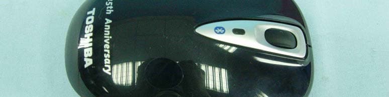
Click to zoom
Application Details
- Equipment Class
- DSS - Part 15 Spread Spectrum Transmitter
- Date of Grant
- May 12, 2010
- Application Purpose
- Original Equipment
- Date of Application
- May 12, 2010
- Equipment Note
- Toshiba Bluetooth Laser Mouse
- Frequency Range
- 2402.00000000 - 2480.00000000
- Company
- Dynabook Inc.
- Country
- Japan
Documents & Files
Document Text
Text extracted from the exhibit documents filed with the FCC. Open a document above to read the original.
Users Manual
Bl uetooth Wire less L as er Mouse User ’s M anu al English/Español 2 Bluetooth Laser Mouse Safety icons Indicates an imminently hazardous situation which, if not avoided, will result in death or serious injury. Indicates a potentially hazardous situation which, if not avoided, could result in death or serious injury. Indicates a potentially hazardous situation which, if not avoided, may result in minor or moderate injury. Indicates a potentially hazardous situation which, if not avoided, may result in property damage. Provides important information. This guide contains safety instructions that must be observed to avoid potential hazards that could result in personal injuries, damage to your equipment, or loss of data. These safety cautions have been classified according to the seriousness of the risk, and icons highlight these instructions as follows: Bluetooth Laser Mouse 3 Important Safety Instructions To protect against risk of fire, bodily injury, electric shock or damage to the equipment: Do not immerse any part of this product in water or other liquid. Do not spray liquid on this product or allow excess liquid to drip inside. Do not use this product if it has sustained any type of damage. Disconnect this product before cleaning. Regulatory Compliance FCC Information FCC notice "Declaration of Conformity Information" measures: Reorient or relocate the receiving antenna. Increase the separation between the equipment and receiver. This equipment has been tested and found to comply with the limits for a Class B digital device, pursuant to part 15 of the FCC rules. These limits are designed to provide reasonable protection against harmful interference in a residential installation. This equipment generates, uses and can radiate radio frequency energy and, if not installed and used in accordance with the instructions, may cause harmful interfer- ence to radio communications. However, there is no guarantee that interference will not occur in a particular installation. If this equipment does cause harmful interference to radio or television reception, which can be determined by turning the equipment off and on, the user is encouraged to try to correct the interference by one or more of the following 4 Bluetooth Wireless Laser Mouse Connect the equipment into an outlet on a circuit different from that to which the receiver is connected. Consult the dealer or an experienced radio/TV technician for help. Changes or modifications made to this equipment, not expressly approved by TOSHIBA or parties authorized by TOSHIBA, could void the user’s authority to operate the equipment. FCC Conditions This equipment has been tested and found to comply with Part 15 of the FCC Rules. Operation is subject to the following two conditions: This device may not cause harmful interference. This device must accept any interference received, including interference that may cause undesired operation. Contact Address : : TOSHIBA America Information Systems, Inc. 9740 Irvine Boulevard Irvine, California 92618-1697 Telephone (949) 583-3000 Bluetooth Wireless Laser Mouse 5 Following Information is Only for EU-Member States Disposal of Products Disposal of Batteries and/or Accumulators Pb, Hg, Cd The crossed out wheeled dust bin symbol indicates that products must be collected and disposed of separately from householdwaste. Integrated batteries and accumulators can be disposed ofwith the product. They will be separated at the recycling centres. The black bar indicates that the product was placed on the market after August 13, 2005. By participating in separate collection of products and batteries, you will help to assure the proper disposal of products and batteries and thus help to prevent potential negative consequences for the environment and human health. For more detailed information about the collection and recycling programmes available in your country, please visit our website (http://eu.computers.toshiba-europe.com) or contact your local city office or the shop where you purchased the product. The crossed out wheeled dust bin symbol indicates that batteries and/or accumulators must be collected and disposed ofseparately from household waste. If the battery or accumulator contains more than the specified values of lead (Pb), mercury (Hg), and/or cadmium (Cd) definedin the Battery Directive (2006/66/EC), then the chemical Pb, Hg, Cd symbols for lead (Pb), mercury (Hg) and/or cadmium (Cd) will appear below the crossed out wheeled dust bin symbol. By participating in separate collection of batteries, you will helpto assure the proper disposal of products and batteries and thushelp to prevent potential negative consequences for the environment and human health. For more detailed information about the collection and recycling programmes available in your country, please visit our website (http://eu.computers.toshiba-europe.com) or contact your local city office or the shop where you purchased the product. 6 Bluetooth Wireless Laser Mouse Copyright Statement Disclaimer January 2009, Rev1.0 Trademarks This guide is copyrighted by Toshiba Corporation with all rights reserved. Under the copyright laws, this guide cannot be reproduced in any form without the prior written permission of Toshiba. No patent liability is assumed, however, with respect to the use of the information contained herein. ©2010 by Toshiba Corporation. All rights reserved. Information in this document is subject to change without notice. The manufacturer does not make any representations or warranties (implied or otherwise) regarding the accuracy and completeness of this document and shall in no event be liable for any loss of profit or any commercial damage, including but not limited to special, incidental, consequential, or other damage. Microsoft, Windows, Windows XP, Windows Vista, and Window 7 are either registered trademarks or trademarks of Microsoft Corporation in the United States and/or other countries. Other trademarks or brand names men…
Text truncated - open the document above for the full version.
External Photos
Page 1 CONSTRUCTION PHOTOS OF EUT Page 2
Internal Photos
Page 3 Page 4
RF Exposure Info
Report No: SA990501C01 Report Format Version 3.0.1 1 RF EXPOSURE REPORT REPORT NO.: SA990501C01 MODEL NO.: PA3847X FCC ID: CJ6UPA3847BT ACCORDING: FCC Guidelines for Human Exposure IEEE C95.1 APPLICANT: Toshiba Corporation ADDRESS: Digital Media Network Company Ome Complex, 2-9, Suehiro-cho, Tokyo 198-8710k, Japan ISSUED BY: Bureau Veritas Consumer Products Services (H.K.) Ltd., Taoyuan Branch LAB ADDRESS: No. 47, 14th Ling, Chia Pau Tsuen, Lin Kou Hsiang, Taipei Hsien 244, Taiwan, R.O.C. TEST LOCATION: No. 19, Hwa Ya 2nd Rd, Wen Hwa Tsuen, Kwei Shan Hsiang, Taoyuan Hsien 333, Taiwan, R.O.C. Report No: SA990501C01 Report Format Version 3.0.1 2 No evaluation required if power is below this threshold: F(GHz) mW Low 2.402 High 2.480 24.580 Maximum measured transmitter power: Pout (dBm) Pout (mW) Conducted Power 2.1 1.6 EIRP Power 1.1 1.3 *Note: The antenna is printed antenna with -1.04dBi gain Threshold for no SAR evaluation is 24.580mW Transmitter power is1.6mW Conclusion: No SAR evaluation required since Transmitter Pout is below FCC threshold
Test Report
Report No.: RF990501C01 1 Report Format Version 3.0.1 FCC TEST REPORT REPORT NO.: RF990501C01 MODEL NO.: PA3847X RECEIVED: May 01, 2010 TESTED: May 05, 2010 ISSUED: May 10, 2010 APPLICANT: Toshiba Corporation ADDRESS: Digital Media Network Company Ome Complex, 2-9, Suehiro-cho, Tokyo 198-8710k, Japan ISSUED BY: Bureau Veritas Consumer Products Services (H.K.) Ltd., Taoyuan Branch LAB ADDRESS: No. 47, 14th Ling, Chia Pau Tsuen, Lin Kou Hsiang, Taipei Hsien 244, Taiwan, R.O.C. TEST LOCATION: No. 19, Hwa Ya 2nd Rd, Wen Hwa Tsuen, Kwei Shan Hsiang, Taoyuan Hsien 333, Taiwan, R.O.C. This test report consists of 40 pages in total. It may be duplicated completely for legal use with the approval of the applicant. It should not be reproduced except in full, without the written approval of our laboratory. The client should not use it to claim product endorsement by TAF or any government agencies. The test results in the report only apply to the tested sample. Report No.: RF990501C01 2 Report Format Version 3.0.1 TABLE OF CONTENTS 1. CERTIFICATION..........................................................................................................4 2. SUMMARY OF TEST RESULTS .................................................................................5 2.1 MEASUREMENT UNCERTAINTY...............................................................................6 3. GENERAL INFORMATION ..........................................................................................7 3.1 GENERAL DESCRIPTION OF EUT ............................................................................7 3.2 DESCRIPTION OF TEST MODES ..............................................................................8 3.2.1 CONFIGURATION OF SYSTEM UNDER TEST .........................................................8 3.2.2 TEST MODE APPLICABILITY AND TESTED CHANNEL DETAIL ..............................9 3.2.3 GENERAL DESCRIPTION OF APPLIED STANDARDS ........................................... 11 3.2.4 DESCRIPTION OF SUPPORT UNITS ...................................................................... 11 4. TEST TYPES AND RESULTS ...................................................................................12 4.2 RADIATED EMISSION MEASUREMENT .................................................................12 4.2.1 LIMITS OF RADIATED EMISSION MEASUREMENT...............................................12 4.2.2 TEST INSTRUMENTS...............................................................................................13 4.2.3 TEST PROCEDURES ...............................................................................................14 4.2.4 DEVIATION FROM TEST STANDARD......................................................................14 4.2.5 TEST SETUP.............................................................................................................15 4.2.6 EUT OPERATING CONDITIONS ..............................................................................15 4.2.7 TEST RESULTS ........................................................................................................16 4.3 NUMBER OF HOPPING FREQUENCY USED .........................................................21 4.3.1 LIMIT OF HOPPING FREQUENCY USED................................................................21 4.3.2 TEST INSTRUMENTS...............................................................................................21 4.3.3 TEST PROCEDURES ...............................................................................................21 4.3.4 DEVIATION FROM TEST STANDARD......................................................................22 4.3.5 TEST SETUP.............................................................................................................22 4.3.6 TEST RESULTS ........................................................................................................22 4.4 DWELL TIME ON EACH CHANNEL .........................................................................24 4.4.1 LIMIT OF DWELL TIME USED ..................................................................................24 4.4.2 TEST INSTRUMENTS...............................................................................................24 4.4.3 TEST PROCEDURES ...............................................................................................24 4.4.4 DEVIATION FROM TEST STANDARD......................................................................24 4.4.5 TEST SETUP.............................................................................................................25 4.4.6 TEST RESULTS ........................................................................................................25 4.5 CHANNEL BANDWIDTH ...........................................................................................27 4.5.1 LIMITS OF CHANNEL BANDWIDTH ........................................................................27 4.5.2 TEST INSTRUMENTS...............................................................................................27 4.5.3 TEST PROCEDURE..................................................................................................27 4.5.4 DEVIATION FROM TEST STANDARD......................................................................28 4.5.5 TEST SETUP.............................................................................................................28 4.5.6 EUT OPERATING CONDITION.................................................................................28 4.5.7 TEST RESULTS ........................................................................................................29 4.6 HOPPING CHANNEL SEPARATION.........................................................................30 Report No.: RF990501C01 3 Report Format Version 3.0.1 4.6.1 LIMIT OF HOPPING CHANNEL SEPARATION ........................................................30 4.6.2 TEST INSTRUMENTS..........................…
Text truncated - open the document above for the full version.
Test Setup Photos
1 PHOTOGRAPHS OF THE TEST CONFIGURATION RADIATED EMISSION TEST
Contact Information
Applicant
Ryuichi Kamimura(Senior Manager)
Technical Contact
Bureau Veritas CPS (H.K.) Ltd. Taoyuan BranchGary Chang
[email protected]886-3-3183232
No. 19, Hwa Ya 2nd Rd., Kwei Shan Hsiang · Taoyuan Hsien · Taiwan
Non-Technical Contact
Bureau Veritas CPS (H.K.) Ltd. Taoyuan BranchZoe Chang
[email protected]886-3-3183232
Test Firm
Bureau Veritas CPS (H.K.) Ltd. Taoyuan BranchRichard Chen
Technical Specifications
| # | Rule Parts | Frequency Range | Power Output |
|---|---|---|---|
| 1 | 15C | 2.40 GHz - 2.48 GHz | 2.00 mW |
Other Applications from Dynabook Inc.

CJ6PA5347RT
Oct 20, 2022dynabook Wireless Optical Silent Mouse
Equipment Class
DXX - Part 15 Low Power Communication Device Transmitter
CJ6PYT0XPC
Apr 28, 2021Notebook Computer
Equipment Class
DSS - Part 15 Spread Spectrum Transmitter
CJ6UPA5238WL
Sep 01, 2015dynadock WiAC
Equipment Class
NII - Unlicensed National Information Infrastructure TX
CJ6UPA5144TJ
Aug 07, 2014TransferJet USB Adapter
Equipment Class
JBP - Part 15 Class B Computing Device Peripheral
CJ6UPA5145TJ
Aug 07, 2014TransferJet MicroUSB Adapter
Equipment Class
UWB - Ultra Wideband Transmitter